

Page 1
TrustedTM
PD-TC700
TM
Trusted
I/O Companion Slot Cable 60
Channels
Introduction
M
This document provides detailed information for the types of Trusted
available within the Companion Slot group. These types of cable provide connection facilities between
the Trusted
(FTAs) as required.
The types of Trusted
below.
TM
analogue and digital input/output modules, and TrustedTM Field Termination Assemblies
TM
I/O 60-Channel Companion Slot Cables currently available are listed in Table 1
T
I/O 60-Channel Cables
Cable Type Description
TC-701-02-xmx I/O Companion Slot, Internal, 60 Channel Input to FTA
TC-702-02-xmx I/O Companion Slot, Internal, 60 Channel Input to Flying Lead
TC-703-02-xmx I/O Companion Slot, External, 60 Channel Input to FTA
TC-704-02-xmx I/O Companion Slot, External, 60 Channel Input to Flying Lead
Table 1 TrustedTM I/O Companion Slot Cables
The cables are manufactured to user’s requirements, therefore length and type of cable insulation
must be specified. Length must be specified to the nearest 0.5m in the format xmx, e.g. 2m0 for a
cable length of 2.0m. This detail must be added to the end of the part number. The type of cable
insulation forms part of the cable part number and is denoted by 02 for Low Smoke Low Halogen
(LSLH), flame retardant to IEC 60332-3 Cat A. PVC covered cables are not available. When ordering
cables, it is recommended that the user supplies the details as shown in Table 1.
The maximum recommended I/O cable length is 15m. Cables longer than this may be specified if
necessary but may suffer from voltage drop, offset, crosstalk and noise and will present materials
handling problems.
Internal cables are designed for cables where they are terminated in adjacent enclosures. If the cable
needs to leave the enclosure environment, the External cable has more protection. Note that the
‘External’ cables are not armoured and are not suitable for truly external use and must still be treated
with care. These cables will need protection when drawn through a cable route, and should also not be
pulled by the connector(s). They should enter cabinets through transit/compression blocks and can not
be glanded.
The Companion Slot cables described in this document allow hot-swap modules to be sited in adjacent
slots using a double width chassis socket. For SmartSlot cables, allowing a remote slot to be assigned
as necessary for a hot-swap, please refer to PD TC-600.
This document describes cables for dual modules (typically 60 channel). For TMR modules (typically
40 channel), please refer to PD TC-500 (Smart Slot) and PD TC-200 (Companion Slot).
Issue 10 Dec 07 PD-TC700 1
Page 2

Trusted
Issue Record
ssue
I
Number Date Revised by Technical CheckAuthorised by Modification
8 Sep 05 J W Clark Format
9 Aug 06 N Owens I Vince P Stock Free wire idents
10 Dec 07 N Owens A Holgate P Stock Flame retardance
TM
I/O Companion Slot Cables TC-700
Issue 10 Dec 07 PD-TC700 2
Page 3

Trusted
TM
I/O Companion Slot Cables TC-700
Table of Contents
1. I/O Companion Slot Cable Type TC-701 .....................................................................................7
2. I/O Companion Slot Cable Type TC-702 .....................................................................................8
3. I/O Companion Slot Cable Type TC-703 .....................................................................................9
4. I/O Companion Slot Cable Type TC-704 ...................................................................................10
Figures
Figure 1 I/O Companion Slot Cable Type TC-701....................................................................................7
Figure 2 I/O Companion Slot Cable Type TC-702....................................................................................8
Figure 3 I/O Companion Slot Cable Type TC-703....................................................................................9
Figure 4 I/O Companion Slot Cable Type TC-704.................................................................................10
Tables
Table 1 TrustedTM I/O Companion Slot Cables ........................................................................................1
Table 2 TMR 40 Channel Standard Cable Selection Guide .....................................................................6
Table 3 Dual 60 Channel Standard Cable Selection Guide......................................................................6
Issue 10 Dec 07 PD-TC700 3
Page 4

Trusted
TM
I/O Companion Slot Cables TC-700
Notice
The content of this document is confidential to ICS Triplex Technology Ltd. companies and their
partners. It may not be given away, lent, resold, hired out or made available to a third party for any
purpose without the written consent of ICS Triplex Technology Ltd.
This document contains proprietary information that is protected by copyright. All rights are reserved.
icrosoft, Windows, Windows 95, Windows NT, Windows 2000, and Windows XP are registered
M
trademarks of Microsoft Corporation.
The information contained in this document is subject to change without notice. The reader should, in
all cases, consult ICS Triplex Technology Ltd. to determine whether any such changes have been
made. From time to time, amendments to this document will be made as necessary and will be
distributed by ICS Triplex Technology Ltd.
Information in this documentation set may be subject to change without notice and does not represent
a commitment on the part of ICS Triplex Technology Ltd.
The contents of this document, which may also include the loan of software tools, are subject to the
confidentiality and other clause(s) within the Integrator Agreement and Software License Agreement.
No part of this documentation may be reproduced or transmitted in any form or by any means,
electronic or mechanical, including photocopying and recording, for any purpose, without the express
written permission of ICS Triplex Technology Ltd.
Disclaimer
The illustrations, figures, charts, and layout examples in this manual are intended solely to illustrate the
text of this manual.
The user of, and those responsible for applying this equipment, must satisfy themselves as to the
acceptability of each application and use of this equipment.
This document is based on information available at the time of its publication. While efforts have been
made to be accurate, the information contained herein does not purport to cover all details or variations
in hardware or software, nor to provide for every possible contingency in connection with installation,
operation, or maintenance. Features may be described herein which are present in all hardware or
software systems. ICS Triplex Technology Ltd. assumes no obligation of notice to holders of this
document with respect to changes subsequently made.
ICS Triplex Technology Ltd. makes no representation or warranty, expressed, implied, or statutory with
respect to, and assumes no responsibility for the accuracy, completeness, sufficiency, or usefulness of
the information contained herein. No warranties of merchantability or fitness for purpose shall apply.
Issue 10 Dec 07 PD-TC700 4
Page 5

Trusted
TM
I/O Companion Slot Cables TC-700
Revision and Updating Policy
All new and revised information pertinent to this document shall be issued by ICS Triplex Technology
Ltd. and shall be incorporated into this document in accordance with the enclosed instructions. The
change is to be recorded on the Amendment Record of this document.
Precautionary Information
WARNING
Warning notices call attention to the use of materials, processes, methods, procedures or limits which
must be followed precisely to avoid personal injury or death.
CAUTION
Caution notices call attention to methods and procedures which must be followed to avoid damage to
the equipment.
Notes:
Notes highlight procedures and contain information to assist the user in the understanding of the
information contained in this document
Warning
RADIO FREQUENCY INTERFERENCE
Most electronic equipment is influenced by Radio Frequency Interference (RFI). Caution should be
exercised with regard to the use of portable communications equipment around such equipment.
Signs should be posted in the vicinity of the equipment cautioning against the use of portable
communications equipment.
MAINTENANCE
Maintenance must be performed only by qualified personnel, otherwise personal injury or death, or
damage to the system may be caused.
Caution
HANDLING
Under no circumstances should the module housing be removed.
Associated Documents
Product Descriptions (PD) provide product specific information.
The Safety Manual contains the recommended safety requirements for the safety system design.
The PD8082B – Toolset Suite provides specific guidance on system configuration and application
generation.
The Operator and Maintenance Manual contains general guidelines on maintenance and diagnostic
procedures.
For technical support email: support@icstriplex.com
Issue 10 Dec 07 PD-TC700 5
Page 6

Trusted
TM
I/O Companion Slot Cables TC-700
NTERNAL SMART SLOT INPUT FTA TC-501-
I
VFTA TC-511Flying Lead TC-502-
UTPUT FTA TC-505-
O
VFTA TC-509Flying Lead TC-506-
Integral Power FTA TC-515-
Flying Lead TC-516-
COMPANION SLOT INPUT FTA TC-201-
VFTA TC-211Flying Lead TC-202-
OUTPUT FTA TC-205-
VFTA TC-209Flying Lead TC-206-
Integral Power FTA TC-215-
Flying Lead TC-216-
EXTERNAL SMART SLOT INPUT FTA TC-503-
VFTA TC-512Flying Lead TC-504-
OUTPUT FTA TC-507-
VFTA TC-510Flying Lead TC-508-
Integral Power FTA TC-517-
Flying Lead TC-518-
COMPANION SLOT INPUT FTA TC-203-
VFTA TC-212Flying Lead TC-204-
OUTPUT FTA TC-207-
VFTA TC-210Flying Lead TC-208-
Integral Power FTA TC-217-
Flying Lead TC-218-
Table 2 TMR 40 Channel Standard Cable Selection Guide
INTERNAL SMART SLOT INPUT FTA TC-601-02
COMPANION SLOT INPUT FTA TC-701-02
EXTERNAL SMART SLOT INPUT FTA TC-603-02
COMPANION SLOT INPUT FTA TC-703-02
Table 3 Dual 60 Channel Standard Cable Selection Guide
The types of I/O Companion Slot Cables are described separately in the following sections.
Issue 10 Dec 07 PD-TC700 6
Page 7

Trusted
TM
I/O Companion Slot Cables TC-700
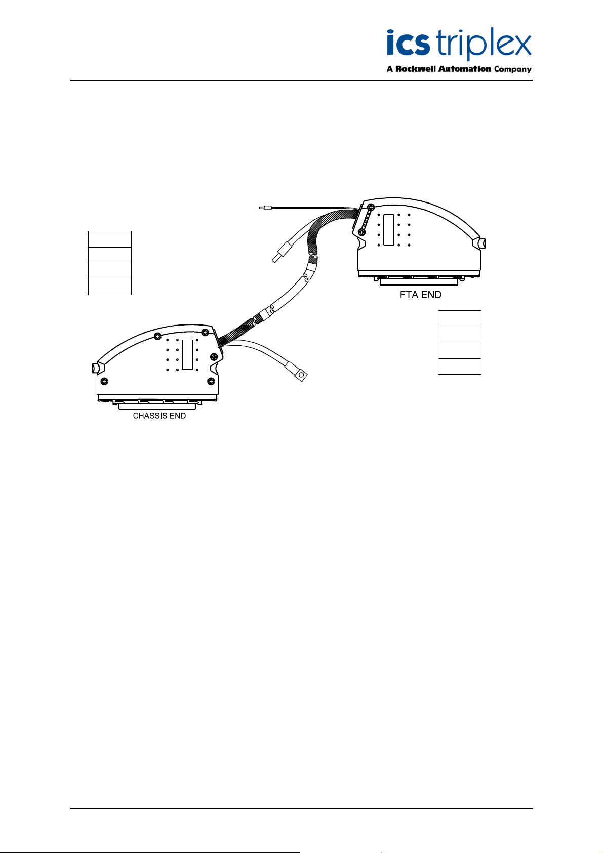
1. I/O Companion Slot Cable Type TC-701
This type of cable, and the modules/field termination assemblies it is used with, is shown in Figure 1
elow.
b
Module
T8402
T8432
T8433
FTA
T8802
T8832
T8833
Figure 1 I/O Companion Slot Cable Type TC-701
This type of Trusted
TM
I/O Companion Slot Cable is designed for use with analogue or digital input
modules and is suitable for connecting input signals from an internal FTA to the module.
The modules and FTAs are matched pairs for this cable:
• T8402 uses T8802
• T8432 uses T8832
• T8433 uses T8833 (non-standard connections on this module need the 60 channel cable).
The chassis end of the multi-core cable is fitted with a 96-way type ‘C’ connector housed in a
double-width hood. The other end of the cable is fitted with a 96-way type ‘R’ connector housed in a
single-width hood enabling the cable to be connected to an FTA.
The multi-core cable is stripped back 1.5m at both ends, then shrouded in nylon Rilgain sheathing.
The ends of the sheathing are heated or fitted with over sleeving to prevent fraying.
At both the chassis and remote end, a sheathed braid allows the connector hood to be wired to safety
earth. At the remote end, the multicore screen drain is wired to a green wire to allow connection to
screen earth.
Issue 10 Dec 07 PD-TC700 7
Page 8

Trusted
TM
I/O Companion Slot Cables TC-700
2. I/O Companion Slot Cable Type TC-702
This type of cable, and the modules/field termination assemblies it is used with, is shown in Figure 2
elow.
b
Module
T8402
T8432
T8433
Figure 2 I/O Companion Slot Cable Type TC-702
This type of Trusted
TM
I/O Companion Slot Cable is designed for use with analogue or digital input
modules and is suitable for connecting input signals from internal terminals to the module.
The chassis end of the multi-core cable is fitted with a 96-way type ‘C’ connector housed in a
double-width hood. The other end of the cable is left as a ‘flying lead’ enabling the cable to be
terminated as required, e.g. connected to conditioned field terminals.
The flying leads are sleeved with identity ferrules marked CH1, CH2, CH3 etc. for channel terminations
or 0V for group reference terminations.
The multi-core cable is stripped back 1.5m at both ends, then shrouded in nylon Rilgain sheathing.
The ends of the sheathing are heated or fitted with over sleeving to prevent fraying.
At the chassis end, a sheathed braid allows the connector hood to be wired to safety earth. At the
remote end, the multicore screen drain is wired to a green wire to allow connection to screen earth.
Issue 10 Dec 07 PD-TC700 8
Page 9
Trusted
TM
I/O Companion Slot Cables TC-700
3. I/O Companion Slot Cable Type TC-703
This type of cable, and the modules/field termination assemblies it is used with, is shown in Figure 3
elow.
b
Module
T8402
T8432
T8433
FTA
T8802
T8832
T8833
Figure 3 I/O Companion Slot Cable Type TC-703
TM
This type of Trusted
I/O Companion Slot Cable is designed for use with analogue or digital input
modules and is suitable for connecting input signals from a remote FTA to the module.
The modules and FTAs are matched pairs for this cable:
• T8402 uses T8802
• T8432 uses T8832
• T8433 uses T8833 (non-standard connections on this module need the 60 channel cable).
The chassis end of the multi-core cable is fitted with a 96-way type ‘C’ connector housed in a
double-width hood. The other end of the cable is fitted with a 96-way type ‘R’ connector housed in a
single-width hood enabling the cable to be connected to an FTA.
The multi-core cable is stripped back 2.0m at the chassis end and 1.5m at the FTA end. Both ends
are then shrouded in nylon Rilgain sheathing. The Rilgain sheathing is cut with a heat gun to prevent
fraying. Joints between the Rilgain sheathing and the multi-core outer sheath are covered with
heatshrink sleeving.
At both the chassis and remote end, a sheathed braid allows the connector hood to be wired to safety
earth. At the remote end, the multicore screen drain is wired to a green wire to allow connection to
screen earth.
Issue 10 Dec 07 PD-TC700 9
Page 10

Trusted
TM
I/O Companion Slot Cables TC-700
4. I/O Companion Slot Cable Type TC-704
This type of cable, and the modules/field termination assemblies it is used with, is shown in Figure 4
elow.
b
Module
T8402
T8432
T8433
Figure 4 I/O Companion Slot Cable Type TC-704
This type of Trusted
TM
I/O Companion Slot Cable is designed for use with analogue or digital input
modules and is suitable for connecting input signals from external terminals to the module.
The chassis end of the multi-core cable is fitted with a 96-way type ‘C’ connector housed in a
double-width hood. The other end of the cable is left as a ‘flying lead’ enabling the cable to be
terminated as required, e.g. connected to conditioned field terminals.
The flying leads are sleeved with identity ferrules marked CH1, CH2, CH3 etc. for channel terminations
or 0V for group reference terminations.
The multi-core cable is stripped back 1.5m at both ends, then shrouded in nylon Rilgain sheathing.
The ends of the sheathing are heated or fitted with over sleeving to prevent fraying.
At the chassis end, a sheathed braid allows the connector hood to be wired to safety earth. At the
remote end, the multicore screen drain is wired to a green wire to allow connection to screen earth.
Issue 10 Dec 07 PD-TC700 10
Page 11

Trusted
TM
I/O Companion Slot Cables TC-700
This page intentionally blank
Issue 10 Dec 07 PD-TC700 11
Page 12

 Loading...