

Page 1

TrustedTM
PD-TC500
Introduction
Trusted
TM
I/O SmartSlot Cables
This document provides detailed information for the types of TrustedTM I/O Cables available within the
SmartSlot group. These types of cable provide connection facilities between the Trusted
and digital input/output modules, and Trusted
Versatile Field Termination Assemblies (VFTAs) as required. Cables are also available with a ‘flying
lead’ at one end to allow connection to conditioned terminals.
M
T
The types of Trusted
The cables are manufactured to user’s requirements, therefore length and type of cable insulation
must be specified. Length must be specified to the nearest 0.5m in the format xmx, e.g. 2m0 for a
cable length of 2.0m. This detail must be added to the end of the part number. Note that some cable
lengths are preferred options and may be easier to obtain; please refer to ICS for details. The type of
cable insulation forms part of the cable part number and is denoted by 01 for PVC, or 02 for Low
Smoke Low Halogen (LSLH). 02 is also flame retardant to IEC 60332-3 Cat A. Note also that 02 may
be a preferred option. When ordering cables, it is recommended that the user supplies the details as
shown in Table 1.
The maximum recommended I/O cable length is 15m. Cables longer than this may be specified if
necessary but may suffer from voltage drop, offset, crosstalk and noise and will present materials
handling problems.
Internal cables are designed for cables where they are terminated in adjacent enclosures. If the cable
needs to leave the enclosure environment, the External cable has more protection. Note that the
‘External’ cables are not armoured and are not suitable for truly external use and must still be treated
with care. These cables will need protection when drawn through a cable route, and should also not be
pulled by the connector(s). They should enter cabinets through transit/compression blocks and can not
be glanded.
I/O SmartSlot Cables currently available are listed in Table 1 on page 7.
M
T
Field Termination Assemblies (FTAs) or Trusted
TM
analogue
M
T
The SmartSlot cables described in this document allow hot-swap modules to be sited in separated
slots as required, linked with a SmartSlot jumper cable. For Companion Slot cables, allowing hot-swap
modules to be sited in adjacent slots using a double width chassis socket, please refer to PD TC-200.
This document describes cables for TMR modules (typically 40 channel). For dual modules (typically
60 channel), please refer to PD TC-600 (Smart Slot) and PD TC-700 (Companion Slot).
For details of the TC-306, TC-308 and TC-310 jumper cables, please refer to PD-TC300.
Issue 13 Apr 10 PD-TC500 1
Page 2
Trusted
Issue Record
ssue
I
Number Date Revised by Technical CheckAuthorised by Modification
7 Sep 05 J W Clark Format
8 Aug 06 N Owens I Vince P Stock Free wire idents
9 Apr 07 N Owens I Vince P Stock Added TC-521
10 Sep 07 N Owens I Vince P Stock Corrections
11 Dec 07 N Owens A Holgate P Stock Flame retardance
12 Aug 08 N Owens A Holgate P Stock 8424 cables
13 Apr 10 S Blackett A Holgate N Owens Fig 11 change
TM
I/O SmartSlot Cables Version 2 TC-500
Issue 13 Apr 10 PD-TC500 2
Page 3

Trusted
TM
I/O SmartSlot Cables Version 2 TC-500
Table of Contents
1. I/O SmartSlot Cable Type TC-501 ...............................................................................................9
2. I/O SmartSlot Cable Type TC-502 .............................................................................................10
3. I/O SmartSlot Cable Type TC-503 .............................................................................................11
4. I/O SmartSlot Cable Type TC-504 .............................................................................................12
5. I/O SmartSlot Cable Type TC-505 .............................................................................................13
6. I/O SmartSlot Cable Type TC-506 .............................................................................................14
7. I/O SmartSlot Cable Type TC-507 .............................................................................................15
8. I/O SmartSlot Cable Type TC-508 .............................................................................................16
9. I/O SmartSlot Cable Type TC-509 .............................................................................................17
10. I/O SmartSlot Cable Type TC-510 .............................................................................................18
11. I/O SmartSlot Cable Type TC-511 .............................................................................................19
12. I/O SmartSlot Cable Type TC-512 .............................................................................................20
13. I/O SmartSlot Cable Type TC-515 .............................................................................................21
14. I/O SmartSlot Cable Type TC-516 .............................................................................................22
15. I/O SmartSlot Cable Type TC-517 .............................................................................................23
16. I/O SmartSlot Cable Type TC-518 .............................................................................................24
17. I/O SmartSlot Cable Type TC-521 .............................................................................................25
18. I/O SmartSlot Cable Type TC-523 .............................................................................................26
Issue 13 Apr 10 PD-TC500 3
Page 4

Trusted
TM
I/O SmartSlot Cables Version 2 TC-500
Figures
Figure 1 I/O SmartSlot Cable Type TC-501 .............................................................................................9
Figure 2 I/O SmartSlot Cable Type TC-502 ...........................................................................................10
Figure 3 I/O SmartSlot Cable Type TC-503 ...........................................................................................11
Figure 4 I/O SmartSlot Cable Type TC-504 ...........................................................................................12
Figure 5 I/O SmartSlot Cable Type TC-505 ...........................................................................................13
Figure 6 I/O SmartSlot Cable Type TC-506 ...........................................................................................14
Figure 7 I/O SmartSlot Cable Type TC-507 ...........................................................................................15
Figure 8 I/O SmartSlot Cable Type TC-508 ...........................................................................................16
Figure 9 I/O SmartSlot Cable Type TC-509 ...........................................................................................17
Figure 10 I/O SmartSlot Cable Type TC-510 .........................................................................................18
Figure 11 I/O SmartSlot Cable Type TC-511 .........................................................................................19
Figure 12 I/O SmartSlot Cable Type TC-512 .........................................................................................20
Figure 13 I/O SmartSlot Cable Type TC-515 .........................................................................................21
Figure 14 I/O SmartSlot Cable Type TC-516 .........................................................................................22
Figure 15 I/O SmartSlot Cable Type TC-517 .........................................................................................23
Figure 16 I/O SmartSlot Cable Type TC-518 .........................................................................................24
Figure 17 I/O SmartSlot Cable Type TC-521 .........................................................................................25
Figure 18 I/O SmartSlot Cable Type TC-523 .........................................................................................26
Tabl es
Table 1 TrustedTM I/O SmartSlot Cables ..................................................................................................7
Table 2 TMR 40 Channel Standard Cable Selection Guide .....................................................................8
Table 3 Dual 60 Channel Standard Cable Selection Guide......................................................................8
Issue 13 Apr 10 PD-TC500 4
Page 5

Trusted
TM
I/O SmartSlot Cables Version 2 TC-500
Notice
The content of this document is confidential to ICS Triplex Technology Ltd. companies and their
partners. It may not be given away, lent, resold, hired out or made available to a third party for any
purpose without the written consent of ICS Triplex Technology Ltd.
This document contains proprietary information that is protected by copyright. All rights are reserved.
icrosoft, Windows, Windows 95, Windows NT, Windows 2000, and Windows XP are registered
M
trademarks of Microsoft Corporation.
The information contained in this document is subject to change without notice. The reader should, in
all cases, consult ICS Triplex Technology Ltd. to determine whether any such changes have been
made. From time to time, amendments to this document will be made as necessary and will be
distributed by ICS Triplex Technology Ltd.
Information in this documentation set may be subject to change without notice and does not represent
a commitment on the part of ICS Triplex Technology Ltd.
The contents of this document, which may also include the loan of software tools, are subject to the
confidentiality and other clause(s) within the Integrator Agreement and Software License Agreement.
No part of this documentation may be reproduced or transmitted in any form or by any means,
electronic or mechanical, including photocopying and recording, for any purpose, without the express
written permission of ICS Triplex Technology Ltd.
Disclaimer
The illustrations, figures, charts, and layout examples in this manual are intended solely to illustrate the
text of this manual.
The user of, and those responsible for applying this equipment, must satisfy themselves as to the
acceptability of each application and use of this equipment.
This document is based on information available at the time of its publication. While efforts have been
made to be accurate, the information contained herein does not purport to cover all details or variations
in hardware or software, nor to provide for every possible contingency in connection with installation,
operation, or maintenance. Features may be described herein which are present in all hardware or
software systems. ICS Triplex Technology Ltd. assumes no obligation of notice to holders of this
document with respect to changes subsequently made.
ICS Triplex Technology Ltd. makes no representation or warranty, expressed, implied, or statutory with
respect to, and assumes no responsibility for the accuracy, completeness, sufficiency, or usefulness of
the information contained herein. No warranties of merchantability or fitness for purpose shall apply.
Issue 13 Apr 10 PD-TC500 5
Page 6

Trusted
TM
I/O SmartSlot Cables Version 2 TC-500
Revision and Updating Policy
All new and revised information pertinent to this document shall be issued by ICS Triplex Technology
Ltd. and shall be incorporated into this document in accordance with the enclosed instructions. The
change is to be recorded on the Amendment Record of this document.
Precautionary Information
WARNING
Warning notices call attention to the use of materials, processes, methods, procedures or limits which
must be followed precisely to avoid personal injury or death.
CAUTION
Caution notices call attention to methods and procedures which must be followed to avoid damage to
the equipment.
Notes:
Notes highlight procedures and contain information to assist the user in the understanding of the
information contained in this document
Warning
RADIO FREQUENCY INTERFERENCE
Most electronic equipment is influenced by Radio Frequency Interference (RFI). Caution should be
exercised with regard to the use of portable communications equipment around such equipment.
Signs should be posted in the vicinity of the equipment cautioning against the use of portable
communications equipment.
MAINTENANCE
Maintenance must be performed only by qualified personnel, otherwise personal injury or death, or
damage to the system may be caused.
Caution
HANDLING
Under no circumstances should the module housing be removed.
Associated Documents
Product Descriptions (PD) provide product specific information.
The Safety Manual contains the recommended safety requirements for the safety system design.
The PD8082B – Toolset Suite provides specific guidance on system configuration and application
generation.
The Operator and Maintenance Manual contains general guidelines on maintenance and diagnostic
procedures.
For technical support email: support@icstriplex.com
Issue 13 Apr 10 PD-TC500 6
Page 7
Trusted
TM
I/O SmartSlot Cables Version 2 TC-500
The types of Trusted
Cable Type Description
TC-501-01-xmx I/O SmartSlot V2 Internal 40 Channel Input to FTA
TC-501-02-xmx I/O SmartSlot V2 Internal 40 Channel Input to FTA
TC-502-01-xmx I/O SmartSlot V2 Internal 40 Channel Input to Flying lead / Free wire
TC-502-02-xmx I/O SmartSlot V2 Internal 40 Channel Input to Flying lead / Free wire
TC-503-01-xmx I/O SmartSlot V2 External 40 Channel Input to FTA
TC-503-02-xmx I/O SmartSlot V2 External 40 Channel Input to FTA
TC-504-01-xmx I/O SmartSlot V2 External 40 Channel Input to Flying lead / Free wire
TC-504-02-xmx I/O SmartSlot V2 External 40 Channel Input to Flying lead / Free wire
TC-505-01-xmx I/O SmartSlot V2 Internal 40 Channel Output to FTA
TC-505-02-xmx I/O SmartSlot V2 Internal 40 Channel Output to FTA
TC-506-01-xmx I/O SmartSlot V2 Internal 40 Channel Output to Flying lead / Free wire
TC-506-02-xmx I/O SmartSlot V2 Internal 40 Channel Output to Flying lead / Free wire
TC-507-01-xmx I/O SmartSlot V2 External 40 Channel Output to FTA
TC-507-02-xmx I/O SmartSlot V2 External 40 Channel Output to FTA
TC-508-01-xmx I/O SmartSlot V2 External 40 Channel Output to Flying lead / Free wire
TC-508-02-xmx I/O SmartSlot V2 External 40 Channel Output to Flying lead / Free wire
TC-509-01-xmx I/O SmartSlot V2 Internal 40 Channel Output to VFTA
M
T
I/O SmartSlot Cables currently available are listed in Table 1 below
TC-509-02-xmx I/O SmartSlot V2 Internal 40 Channel Output to VFTA
TC-510-01-xmx I/O SmartSlot V2 External 40 Channel Output to VFTA
TC-510-02-xmx I/O SmartSlot V2 External 40 Channel Output to VFTA
TC-511-01-xmx I/O SmartSlot V2 Internal 40 Channel Input to VFTA
TC-511-02-xmx I/O SmartSlot V2 Internal 40 Channel Input to VFTA
TC-512-01-xmx I/O SmartSlot V2 External 40 Channel Input to VFTA
TC-512-02-xmx I/O SmartSlot V2 External 40 Channel Input to VFTA
TC-515-01-xmx I/O SmartSlot V2 Internal 40 Channel Output to FTA ( Integral Power )
TC-515-02-xmx I/O SmartSlot V2 Internal 40 Channel Output to FTA ( Integral Power )
TC-516-01-xmx I/O SmartSlot V2 Internal 40 Channel Output to Flying lead / Free wire ( Integral
TC-516-02-xmx I/O SmartSlot V2 Internal 40 Channel Output to Flying lead / Free wire ( Integral
TC-517-01-xmx I/O SmartSlot V2 External 40 Channel Output to FTA ( Integral Power )
TC-517-02-xmx I/O SmartSlot V2 External 40 Channel Output to FTA ( Integral Power )
TC-518-01-xmx I/O SmartSlot V2 External 40 Channel Output to Flying lead / Free wire ( Integral
TC-518-02-xmx I/O SmartSlot V2 External 40 Channel Output to Flying lead / Free wire ( Integral
TC-521-01-xmx I/O SmartSlot V2 Internal T8472 16 Channel Output to T8871 FTA
TC-521-02-xmx I/O SmartSlot V2 Internal T8472 16 Channel Output to T8871 FTA
Power )
Power )
Power )
Power )
Table 1 TrustedTM I/O SmartSlot Cables
Issue 13 Apr 10 PD-TC500 7
Page 8
Trusted
TM
I/O SmartSlot Cables Version 2 TC-500
NTERNAL SMART SLOT INPUT FTA TC-501-
I
VFTA TC-511Flying Lead TC-502-
UTPUT FTA TC-505-
O
VFTA TC-509Flying Lead TC-506-
Integral Power FTA TC-515-
Flying Lead TC-516-
COMPANION SLOT INPUT FTA TC-201-
VFTA TC-211Flying Lead TC-202-
OUTPUT FTA TC-205-
VFTA TC-209Flying Lead TC-206-
Integral Power FTA TC-215-
Flying Lead TC-216-
EXTERNAL SMART SLOT INPUT FTA TC-503-
VFTA TC-512Flying Lead TC-504-
OUTPUT FTA TC-507-
VFTA TC-510Flying Lead TC-508-
Integral Power FTA TC-517-
Flying Lead TC-518-
COMPANION SLOT INPUT FTA TC-203-
VFTA TC-212Flying Lead TC-204-
OUTPUT FTA TC-207-
VFTA TC-210Flying Lead TC-208-
Integral Power FTA TC-217-
Flying Lead TC-218-
Table 2 TMR 40 Channel Standard Cable Selection Guide
INTERNAL SMART SLOT INPUT FTA TC-601-02
COMPANION SLOT INPUT FTA TC-701-02
EXTERNAL SMART SLOT INPUT FTA TC-603-02
COMPANION SLOT INPUT FTA TC-703-02
Table 3 Dual 60 Channel Standard Cable Selection Guide
The various types of I/O SmartSlot Cables, i.e. TC-501, TC-502 etc. are described separately in the
following sections.
Issue 13 Apr 10 PD-TC500 8
Page 9
Trusted
TM
I/O SmartSlot Cables Version 2 TC-500
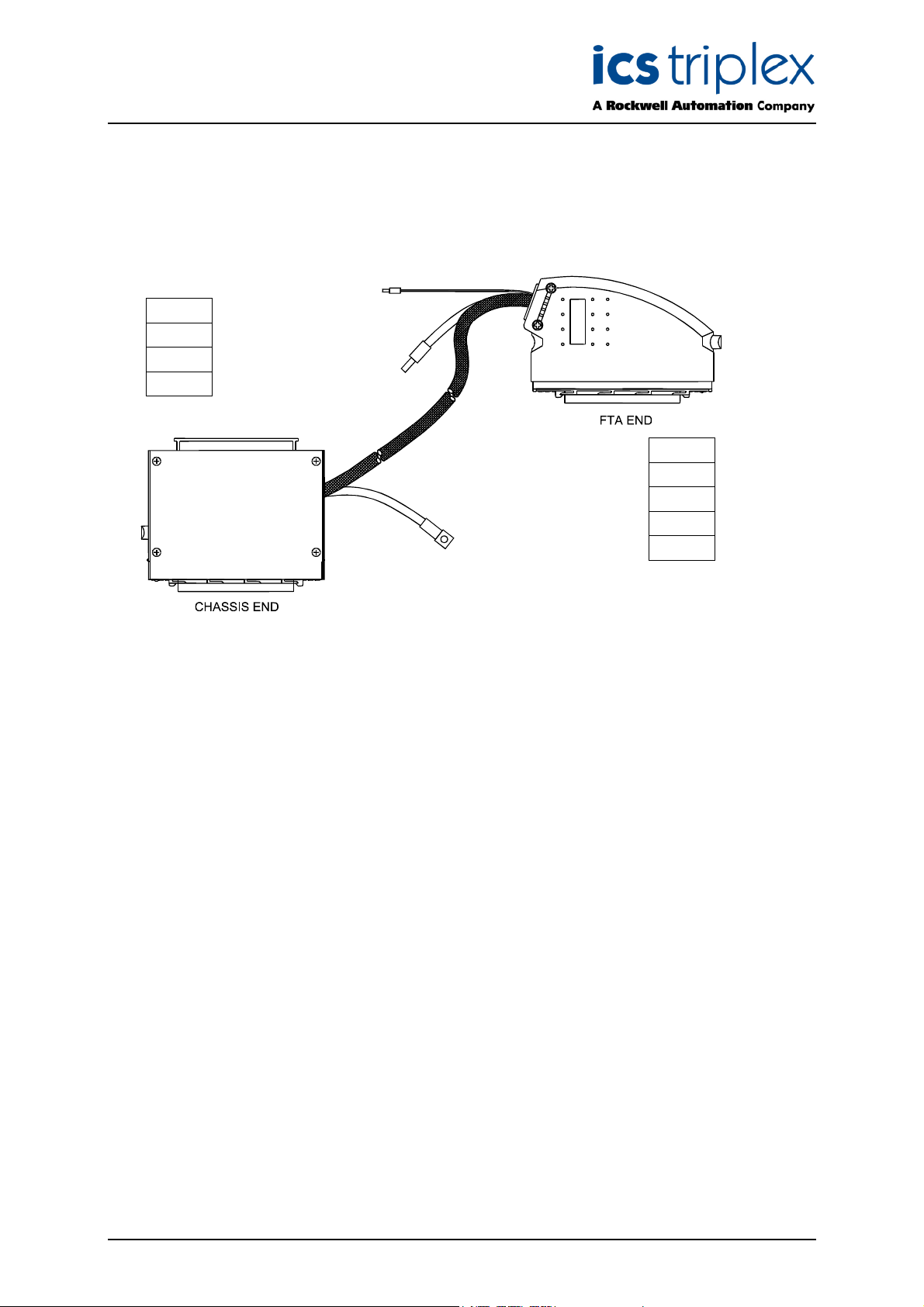
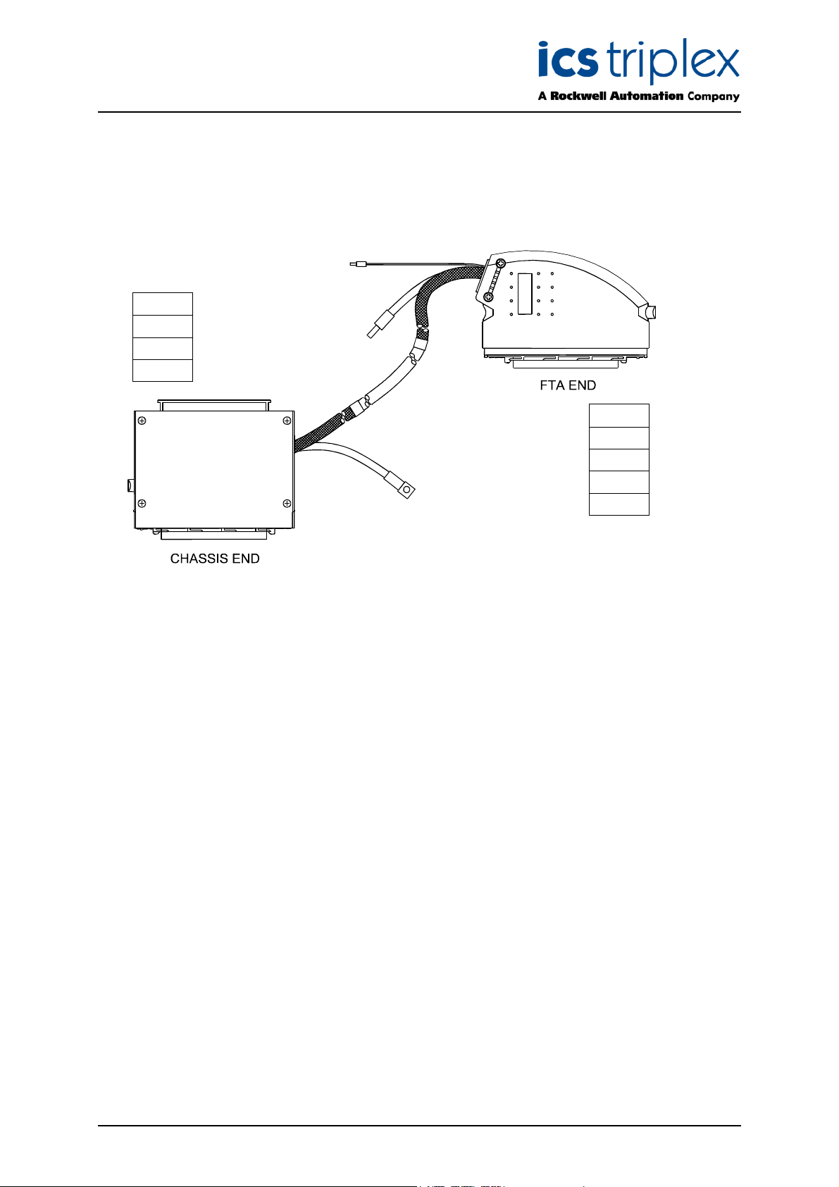
1. I/O SmartSlot Cable Type TC-501
This type of cable, and the modules/field termination assemblies it is used with, is shown in Figure 1
elow.
b
Module
T8403
T8423
T8431
FTA
T8800
T8801
T8821
T8830/1
Figure 1 I/O SmartSlot Cable Type TC-501
TM
This type of Trusted
I/O SmartSlot Cable is designed for use with analogue or digital input modules
and is suitable for connecting input signals from an internal FTA to the module.
The chassis end of the multi-core cable is fitted with a 96-way type ‘C’ connector housed in a
single-width hood (Type TC-500). The other end of the cable is fitted with a 96-way type ‘R’ connector
housed in a single-width hood enabling the cable to be connected to an FTA.
The multi-core cable is stripped back 1.5m at both ends, then shrouded in nylon Rilgain sheathing.
The ends of the sheathing are heated or fitted with over sleeving to prevent fraying.
At both the chassis and remote end, a sheathed braid allows the connector hood to be wired to safety
earth. At the remote end, the multicore screen drain is wired to a green wire to allow connection to
screen earth.
Issue 13 Apr 10 PD-TC500 9
Page 10

Trusted
TM
I/O SmartSlot Cables Version 2 TC-500
2. I/O SmartSlot Cable Type TC-502
This type of cable, and the modules it is used with, is shown in Figure 2 below.
Module
T8403
T8423
T8431
Figure 2 I/O SmartSlot Cable Type TC-502
This type of Trusted
TM
I/O SmartSlot Cable is designed for use with analogue or digital input modules
and is suitable for connecting input signals from internal terminals to the module.
The chassis end of the multi-core cable is fitted with a 96-way type ‘C’ connector housed in a
single-width hood (Type TC-500). The other end of the cable is left as a ‘flying lead’ enabling the cable
to be terminated as required, e.g. connected to conditioned field terminals.
The flying leads are sleeved with identity ferrules marked CH1, CH2, CH3 etc. for channel terminations
or 0V for group reference terminations.
The multi-core cable is stripped back 1.5m at both ends, then shrouded in nylon Rilgain sheathing.
The ends of the sheathing are heated or fitted with over sleeving to prevent fraying.
At the chassis end, a sheathed braid allows the connector hood to be wired to safety earth. At the
remote end, the multicore screen drain is wired to a green wire to allow connection to screen earth.
Issue 13 Apr 10 PD-TC500 10
Page 11
Trusted
TM
I/O SmartSlot Cables Version 2 TC-500
3. I/O SmartSlot Cable Type TC-503
This type of cable, and the modules/field termination assemblies it is used with, is shown in Figure 3
elow.
b
Module
T8403
T8423
T8431
FTA
T8800
T8801
T8821
T8830/1
Figure 3 I/O SmartSlot Cable Type TC-503
This type of Trusted
TM
I/O SmartSlot Cable is designed for use with analogue or digital input modules
and is suitable for connecting input signals from a remote FTA to the module.
The chassis end of the multi-core cable is fitted with a 96-way type ‘C’ connector housed in a
single-width hood (TC-500). The other end of the cable is fitted with a 96-way type ‘R’ connector
housed in a single-width hood enabling the cable to be connected to an FTA.
The multi-core cable is stripped back 2.0m at the chassis end and 1.5m at the FTA end. Both ends
are then shrouded in nylon Rilgain sheathing. The Rilgain sheathing is cut with a heat gun to prevent
fraying. Joints between the Rilgain sheathing and the multi-core outer sheath are taped over with
25mm PVC insulating tape and then covered with heatshrink sleeving.
At both the chassis and remote end, a sheathed braid allows the connector hood to be wired to safety
earth. At the remote end, the multicore screen drain is wired to a green wire to allow connection to
screen earth.
Issue 13 Apr 10 PD-TC500 11
Page 12

Trusted
TM
I/O SmartSlot Cables Version 2 TC-500
4. I/O SmartSlot Cable Type TC-504
This type of cable, and the modules it is used with, is shown in Figure 4 below.
Module
T8403
T8423
T8431
Figure 4 I/O SmartSlot Cable Type TC-504
TM
This type of Trusted
I/O SmartSlot Cable is designed for use with analogue or digital input modules
and is suitable for connecting input signals from external terminals to the module.
The chassis end of the multi-core cable is fitted with a 96-way type ‘C’ connector housed in a
single-width hood (TC-500). The other end of the cable is left as a ‘flying lead’ enabling the cable to be
terminated as required, e.g. connected to conditioned field terminals.
The flying leads are sleeved with identity ferrules marked CH1, CH2, CH3 etc. for channel terminations
or 0V for group reference terminations.
The multi-core cable is stripped back 2.0m at both ends, then shrouded in nylon Rilgain sheathing.
The Rilgain sheathing is cut with a heat gun to prevent fraying. Joints between the Rilgain sheathing
and the multi-core outer sheath are taped over with 25mm PVC insulating tape and then covered with
heatshrink sleeving.
At the chassis end, a sheathed braid allows the connector hood to be wired to safety earth. At the
remote end, the multicore screen drain is wired to a green wire to allow connection to screen earth.
Issue 13 Apr 10 PD-TC500 12
Page 13

Trusted
TM
I/O SmartSlot Cables Version 2 TC-500
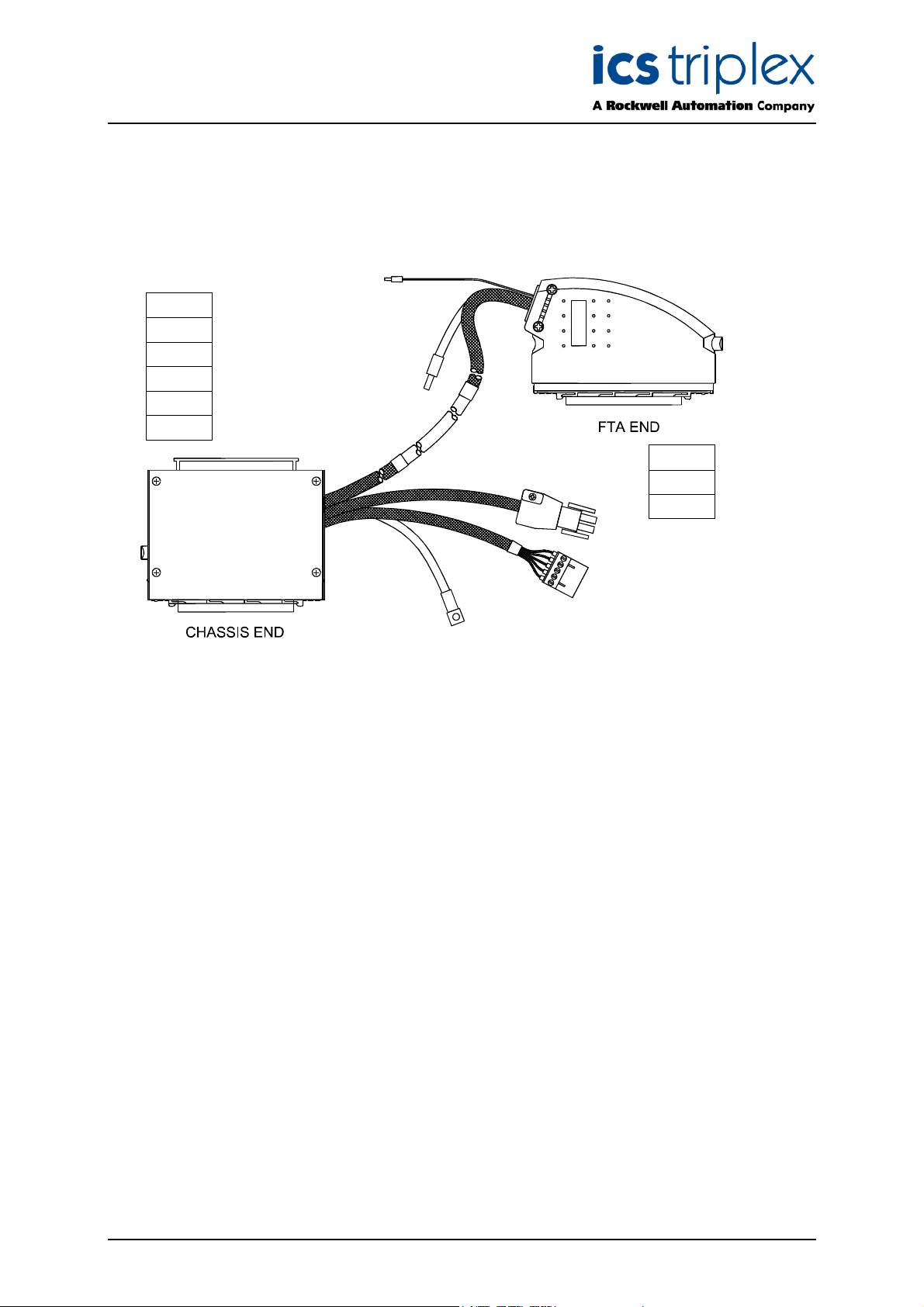
5. I/O SmartSlot Cable Type TC-505
This type of cable, and the modules/field termination assemblies it is used with, is shown in Figure 5
elow.
b
Module
T8444
T8451
T8461
T8471
T8480
FTA
T8850
T8870
Figure 5 I/O SmartSlot Cable Type TC-505
TM
This type of Trusted
I/O SmartSlot Cable is designed for use with digital 24V/120V dc or analogue
output modules and is suitable for connecting output signals from the module to an internal FTA.
Three multi-core cables are used for this application. The chassis end of the multi-core cable is fitted
with a 96-way type ‘C’ connector housed in a single-width hood (TC-500). The non-chassis end of
multi-core 1 is fitted with a 96-way type ‘R’ connector housed in a single-width hood enabling
connection to an FTA. The non-chassis end of multi-core 2 is fitted with a 5-way Weidmuller BLZF 3.5
series connector enabling the cable to be terminated at a T8290 Output Power Distribution Unit. This
cable is used for field power return. The non-chassis end of multi-core 3 is fitted with a 6-way Amp
plug used to connect power to the field from a T8290 or T8297 and is made up of five individual 2.5mm
wires contained within Rilgain sleeving.
The 0V connection at the chassis end allows a module reference so that it can measure its output
voltage, this must be connected to the field 0 Volts.
The FTA contains isolated power group field 0 Volts which connect to field 0V supply. Commoning of
the reference is obtained by a connection between this field supply and the T8290 Output power
distribution unit (TB1 pins 1 and 2).
Multi-core 1 is stripped back 1.5m at both ends. Multi-cores 1, 2 and 3 are shrouded in nylon Rilgain
sheathing. The ends of the sheathing are heated, or over sleeved as required to prevent fraying.
At both the chassis and remote end, a sheathed braid allows the connector hood to be wired to safety
earth. At the remote end, the multicore screen drain is wired to a green wire to allow connection to
screen earth.
Issue 13 Apr 10 PD-TC500 13
Page 14

Trusted
TM
I/O SmartSlot Cables Version 2 TC-500
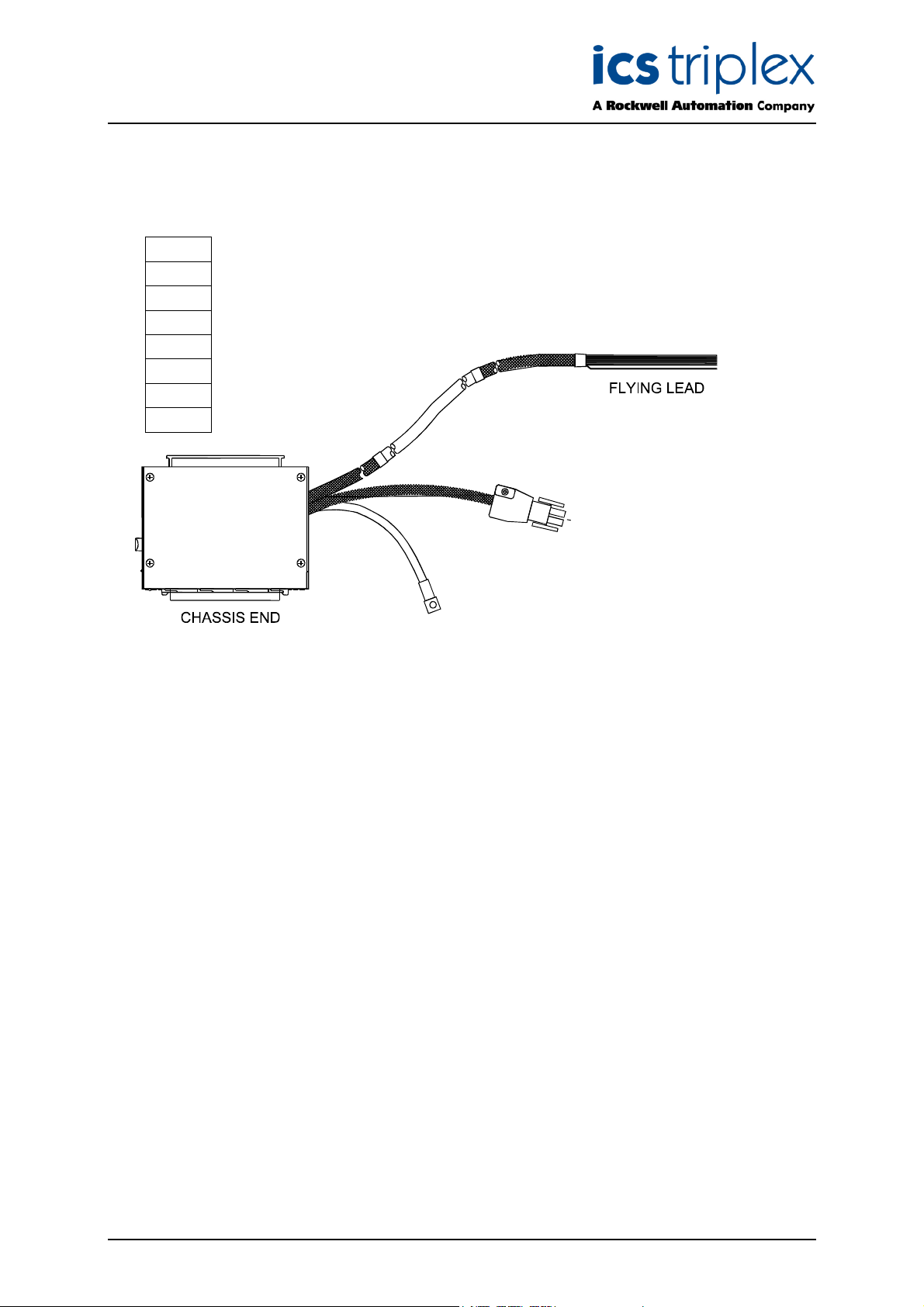
6. I/O SmartSlot Cable Type TC-506
This type of cable, and the modules it is used with, is shown in Figure 6 below.
Module
T8444
T8448
T8449
T8451
T8461
T8471
T8480
Figure 6 I/O SmartSlot Cable Type TC-506
TM
This type of Trusted
I/O SmartSlot Cable is designed for use with digital 24V/120V dc or analogue
output modules and is suitable for connecting output signals from the module to internal terminals.
Two multi-core cables are required for this application. The chassis end of the multi-core 1 is fitted
with a 96-way type ‘C’ connector housed in a single-width hood (TC-500). The other end of multi-core
1 is left as a ‘flying lead’ enabling the cable to be terminated as required, e.g. connected to conditioned
field terminals. The non-chassis end of multi-core 2 is fitted with a 6-way Amp plug used to connect
power to the field from a T8290 or T8297 and is made up of five individual 2.5mm wires contained
within Rilgain sleeving.
The flying leads are sleeved with identity ferrules marked CH1, CH2, CH3 etc. for channel terminations
or V FIELD RTNGRP1 to V FIELD RTNGRP5 for group reference terminations.
The 0V connections at the flying leads end allows a module reference so that it can measure its output
voltage, these must be connected to the field 0 Volts.
The flying lead multi-core contains isolated power group field 0 Volts which connect to field 0V supply.
Commoning of the reference is obtained by a connection to this field supply.
Multi-core 1 is stripped back 1.5m at both ends. Multi-cores 1 and 2 are shrouded in nylon Rilgain
sheathing. The ends of the sheathing are heated, or over sleeved as required to prevent fraying.
At the chassis end, a sheathed braid allows the connector hood to be wired to safety earth. At the
remote end, the multicore screen drain is wired to a green wire to allow connection to screen earth.
Issue 13 Apr 10 PD-TC500 14
Page 15
Trusted
TM
I/O SmartSlot Cables Version 2 TC-500
7. I/O SmartSlot Cable Type TC-507
This type of cable, and the modules/field termination assemblies it is used with, is shown in Figure 7
elow.
b
Module
T8444
T8451
T8461
T8471
T8480
FTA
T8850
T8870
Figure 7 I/O SmartSlot Cable Type TC-507
TM
This type of Trusted
I/O SmartSlot Cable is designed for use with digital 24V/120V dc or analogue
output modules and is suitable for connecting output signals from the module to an external FTA.
Three multi-core cables are used for this application. The chassis end of the multi-core cable is fitted
with a 96-way type ‘C’ connector housed in a single-width hood (TC-500). The non-chassis end of
multi-core 1 is fitted with a 96-way type ‘R’ connector housed in a single-width hood enabling
connection to an FTA. The non-chassis end of multi-core 2 is fitted with a 5-way Weidmuller BLZF 3.5
series connector enabling the cable to be terminated at a T8290 Output Power Distribution Unit. This
cable is used for field power return. The non-chassis end of multi-core 3 is fitted with a 6-way Amp
plug used to connect power to the field from a T8290 or T8297 and is made up of five individual 2.5mm
wires contained within Rilgain sleeving.
The 0V connection at the chassis end allows a module reference so that it can measure its output
voltage, this must be connected to the field 0 Volts.
The FTA contains isolated power group field 0 Volts which connect to field 0V supply. Commoning of
the reference is obtained by a connection between this field supply and the T8290 Output power
distribution unit (TB1 pins 1 and 2).
Multi-core 1 is stripped back 1.5m at both ends. Multi-cores 1, 2 and 3 are shrouded in nylon Rilgain
sheathing. The ends of the sheathing are heated, or over sleeved as required to prevent fraying.
At both the chassis and remote end, a sheathed braid allows the connector hood to be wired to safety
earth. At the remote end, the multicore screen drain is wired to a green wire to allow connection to
screen earth.
Issue 13 Apr 10 PD-TC500 15
Page 16
Trusted
TM
I/O SmartSlot Cables Version 2 TC-500
8. I/O SmartSlot Cable Type TC-508
This type of cable, and the modules it is used with, is shown in Figure 8 below.
Module
T8444
T8448
T8449
T8451
T8461
T8471
T8480
Figure 8 I/O SmartSlot Cable Type TC-508
TM
This type of Trusted
I/O SmartSlot Cable is designed for use with digital 24V/120V dc or analogue
output modules and is suitable for connecting output signals from the module to external terminals.
Two multi-core cables are required for this application. The chassis end of the multi-core 1 is fitted
with a 96-way type ‘C’ connector housed in a single-width hood (TC-500). The other end of multi-core
1 is left as a ‘flying lead’ enabling the cable to be terminated as required, e.g. connected to conditioned
field terminals. The non-chassis end of multi-core 2 is fitted with a 6-way Amp plug used to connect
power to the field from a T8290 or T8297 and is made up of five individual 2.5mm wires contained
within Rilgain sleeving.
The flying leads are sleeved with identity ferrules marked CH1, CH2, CH3 etc. for channel terminations
or V FIELD RTNGRP1 to V FIELD RTNGRP5 for group reference terminations.
The 0V connections at the flying leads end allows a module reference so that it can measure its output
voltage, these must be connected to the field 0 Volts.
The flying lead multi-core contains isolated power group field 0 Volts which connect to field 0V supply.
Commoning of the reference is obtained by a connection to this field supply.
Multi-core 1 is stripped back 1.5m at both ends. Multi-cores 1 and 2 are shrouded in nylon Rilgain
sheathing. The ends of the sheathing are heated, or over sleeved as required to prevent fraying.
At the chassis end, a sheathed braid allows the connector hood to be wired to safety earth. At the
remote end, the multicore screen drain is wired to a green wire to allow connection to screen earth.
Issue 13 Apr 10 PD-TC500 16
Page 17

Trusted
TM
I/O SmartSlot Cables Version 2 TC-500
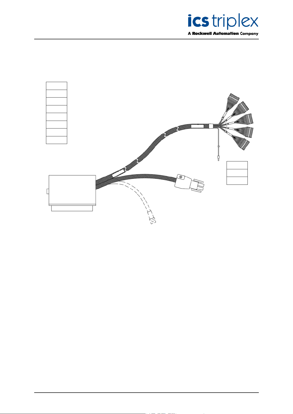
9. I/O SmartSlot Cable Type TC-509
This type of cable, and the modules/versatile field termination assemblies it is used with, is shown in
igure 9 below.
F
Module
T8444
T8448
T8449
T8451
T8461
T8471
T8480
VFTA
T8842
T8845
Figure 9 I/O SmartSlot Cable Type TC-509
TM
This type of Trusted
I/O SmartSlot Cable is designed for use with digital 24V/120V dc and analogue
output modules and is suitable for connecting output signals from the module to an internal VFTA. For
the T8448 and T8449, it is recommended to use the T8842 VFTA. PD-T8842 describes the possible
circuits that may be configured for this VFTA.
Two multi-core cables are required for this application. The chassis end of the multi-core 1 is fitted
with a 96-way type ‘C’ connector housed in a single-width hood (TC-500). The other end of multi-core
1 is fitted with five 10-way Weidmuller BLZF 3.5 series connectors enabling the cable to be terminated
at a VFTA. The non-chassis end of multi-core 2 is fitted with a 6-way Amp plug used to connect power
to the field from a T8290 or T8297. This cable is made up of five individual 2.5mm wires contained
within Rilgain sleeving. For analogue output or low current digital output modules using this cable, the
T8297 is recommended.
The VFTA contains isolated power group field 0 Volts which connect to field 0V supply. Commoning of
the reference is obtained by a connection to this field supply.
Multi-core 1 is stripped back 1.5m at both ends, then shrouded in nylon Rilgain sheathing. Multi-core 2
is shrouded in nylon Rilgain sheathing. The ends of the sheathing are heated or fitted with over
sleeving to prevent fraying.
At the chassis end, a sheathed braid allows the connector hood to be wired to safety earth. At the
remote end, the multicore screen drain is wired to a green wire to allow connection to screen earth.
Issue 13 Apr 10 PD-TC500 17
Page 18
Trusted
TM
I/O SmartSlot Cables Version 2 TC-500
10. I/O SmartSlot Cable Type TC-510
This type of cable, and the modules/versatile field termination assemblies it is used with, is shown in
igure 10 below.
F
Module
T8444
T8448
T8449
T8451
T8461
T8471
T8480
VFTA
T8842
T8845
Figure 10 I/O SmartSlot Cable Type TC-510
TM
This type of Trusted
I/O SmartSlot Cable is designed for use with digital 24V/120V dc and analogue
output modules and is suitable for connecting output signals from the module to an external VFTA. For
the T8448 and T8449, it is recommended to use the T8842 VFTA. PD-T8842 describes the possible
circuits that may be configured for this VFTA.
Two multi-core cables are required for this application. The chassis end of the multi-core 1 is fitted
with a 96-way type ‘C’ connector housed in a single-width hood (TC-500). The other end of multi-core
1 is fitted with five 10-way Weidmuller BLZF 3.5 series connectors enabling the cable to be terminated
at a VFTA. The non-chassis end of multi-core 2 is fitted with a 6-way Amp plug used to connect power
to the field from a T8290 or T8297. This cable is made up of five individual 2.5mm wires contained
within Rilgain sleeving. For analogue output or low current digital output modules using this cable, the
T8297 is recommended.
The VFTA contains isolated power group field 0 Volts which connect to field 0V supply. Commoning of
the reference is obtained by a connection to this field supply.
Multi-core 1 is stripped back 1.5m at both ends, then shrouded in nylon Rilgain sheathing. Multi-core 2
is shrouded in nylon Rilgain sheathing. The ends of the sheathing are heated or fitted with over
sleeving to prevent fraying.
At the chassis end, a sheathed braid allows the connector hood to be wired to safety earth. At the
remote end, the multicore screen drain is wired to a green wire to allow connection to screen earth.
Issue 13 Apr 10 PD-TC500 18
Page 19

Trusted
TM
I/O SmartSlot Cables Version 2 TC-500
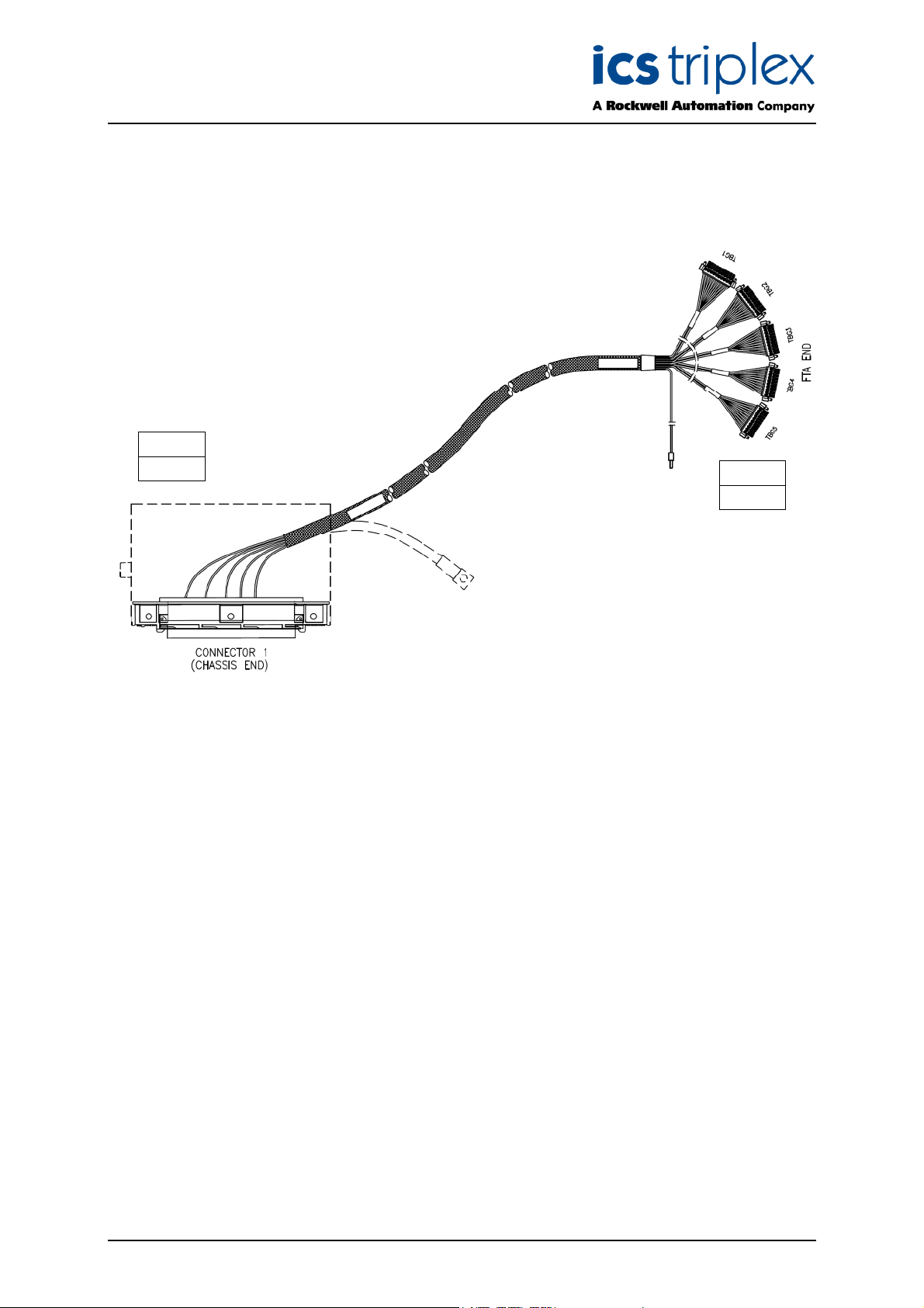
11. I/O SmartSlot Cable Type TC-511
This type of cable, and the modules/field termination assemblies it is used with, is shown in Figure 11
elow.
b
Module
T8403
T8423
T8431
VFTA
T8842
Figure 11 I/O SmartSlot Cable Type TC-511
This type of Trusted
TM
I/O SmartSlot Cable is designed for use with analogue or digital input modules
and is suitable for connecting input signals from an internal VFTA to the module.
The chassis end of the multi-core cable is fitted with a 96-way type ‘C’ connector housed in a
single-width hood (TC500). The other end of the multi-core is fitted with one 7-way and five 10-way
Weidmuller BLZF 3.5 series connectors enabling the cable to be terminated at a VFTA.
The VFTA contains isolated power group field 0 Volts which connect to field 0V supply. Commoning of
the reference is obtained by a connection to this field supply.
The multi-core is stripped back 1.5m at both ends, then shrouded in nylon Rilgain sheathing. The ends
of the sheathing are heated or fitted with over sleeving to prevent fraying.
At the chassis end, a sheathed braid allows the connector hood to be wired to safety earth. At the
remote end, the multicore screen drain is wired to a green wire to allow connection to screen earth.
Issue 13 Apr 10 PD-TC500 19
Page 20

Trusted
TM
I/O SmartSlot Cables Version 2 TC-500
12. I/O SmartSlot Cable Type TC-512
This type of cable, and the modules/versatile field termination assemblies it is used with, is shown in
igure 12 below.
F
Module
T8403
T8423
T8431
VFTA
T8842
Figure 12 I/O SmartSlot Cable Type TC-512
TM
This type of Trusted
I/O SmartSlot Cable is designed for use with analogue or digital input modules
and is suitable for connecting input signals from an external VFTA to the module.
The chassis end of the multi-core cable is fitted with a 96-way type ‘C’ connector housed in a
single-width hood (TC-500). The other end of the multi-core is fitted with one 7-way and five 10-way
Weidmuller BLZF 3.5 series connectors enabling the cable to be terminated at a VFTA.
The VFTA contains isolated power group field 0 Volts which connect to field 0V supply. Commoning of
the reference is obtained by a connection to this field supply.
The multi-core is stripped back 1.5m at both ends, then shrouded in nylon Rilgain sheathing. The ends
of the sheathing are heated or fitted with over sleeving to prevent fraying.
At the chassis end, a sheathed braid allows the connector hood to be wired to safety earth. At the
remote end, the multicore screen drain is wired to a green wire to allow connection to screen earth.
Issue 13 Apr 10 PD-TC500 20
Page 21

Trusted
TM
I/O SmartSlot Cables Version 2 TC-500
13. I/O SmartSlot Cable Type TC-515
This type of cable, and the modules/field termination assemblies it is used with, is shown in Figure 13
elow.
b
Module
T8451
T8471
T8461
T8480
FTA
T8850
T8870
Figure 13 I/O SmartSlot Cable Type TC-515
TM
This type of Trusted
I/O SmartSlot Cable is designed for use with 24V or 120V dc digital output
modules and is suitable for connecting output signals from the module to an internal FTA. Power
connections are integral with this type of cable.
The chassis end of the multi-core cable is fitted with a 96-way type ‘C’ connector housed in a
single-width hood (TC-500). The other end of the cable is fitted with a 96-way type ‘R’ connector
housed in a single-width hood enabling the cable to be connected to an FTA.
Using this cable, the field power is connected at the FTA, which has indicators for each power group
which are voltage sensitive. For this reason, the T8850 FTA should be used with the T8451 and the
T8870 with the T8471.
The 0V connection at the FTA end allows a module reference so that it can measure its output voltage,
this must be connected to the field 0 Volts.
The FTA contains isolated power group field 0 Volts which connect to field 0V supply. Commoning of
the reference is obtained by a connection to this field supply.
The multi-core cable is stripped back 1.5m at both ends, then shrouded in nylon Rilgain sheathing.
The ends of the sheathing are heated or fitted with over sleeving to prevent fraying.
At both the chassis and remote end, a sheathed braid allows the connector hood to be wired to safety
earth. At the remote end, the multicore screen drain is wired to a green wire to allow connection to
screen earth.
Issue 13 Apr 10 PD-TC500 21
Page 22

Trusted
TM
I/O SmartSlot Cables Version 2 TC-500
14. I/O SmartSlot Cable Type TC-516
This type of cable, and the modules it is used with, is shown in Figure 14 below.
Module
T8444
T8448
T8449
T8451
T8461
T8471
T8480
Figure 14 I/O SmartSlot Cable Type TC-516
TM
This type of Trusted
I/O SmartSlot Cable is designed for use with digital and analogue output
modules and is suitable for connecting output signals from the module to internal terminals. Power
connections are integral with this type of cable.
The chassis end of the multi-core cable is fitted with a 96-way type ‘C’ connector housed in a
single-width hood (TC-500). The other end of the cable is left as a ‘flying lead’ enabling the cable to be
terminated as required, e.g. connected to conditioned field terminals.
The flying leads are sleeved with identity ferrules marked CH1, CH2, CH3 etc. for channel terminations
or V FIELD GRP1 to V FIELD GRP5 for group field supply terminations or V FIELD RTNGRP1 to V
FIELD RTNGRP5 for group reference terminations.
The 0V connections at the flying lead ends allows a module reference so that it can measure its output
voltage, this must be connected to the field 0 Volts.
The flying lead multi-core contains isolated power group field 0 Volts which connect to field 0V supply.
Commoning of the reference is obtained by a connection to this field supply.
The multi-core cable is stripped back 1.5m at both ends, then shrouded in nylon Rilgain sheathing.
The ends of the sheathing are heated or fitted with over sleeving to prevent fraying.
At the chassis end, a sheathed braid allows the connector hood to be wired to safety earth. At the
remote end, the multicore screen drain is wired to a green wire to allow connection to screen earth.
Issue 13 Apr 10 PD-TC500 22
Page 23

Trusted
TM
I/O SmartSlot Cables Version 2 TC-500
15. I/O SmartSlot Cable Type TC-517
This type of cable, and the modules/field termination assemblies it is used with, is shown in Figure 15
elow.
b
Module
T8451
T8471
T8461
T8480
FTA
T8850
T8870
Figure 15 I/O SmartSlot Cable Type TC-517
TM
This type of Trusted
I/O SmartSlot Cable is designed for use with 24V or 120V dc digital output
modules and is suitable for connecting output signals from the module to an internal FTA. Power
connections are integral with this type of cable.
The chassis end of the multi-core cable is fitted with a 96-way type ‘C’ connector housed in a
single-width hood (TC-500). The other end of the cable is fitted with a 96-way type ‘R’ connector
housed in a single-width hood enabling the cable to be connected to an FTA.
Using this cable, the field power is connected at the FTA, which has indicators for each power group
which are voltage sensitive. For this reason, the T8850 FTA should be used with the T8451 and the
T8870 with the T8471.
The 0V connection at the FTA end allows a module reference so that it can measure its output voltage,
this must be connected to the field 0 Volts.
The FTA contains isolated power group field 0 Volts which connect to field 0V supply. Commoning of
the reference is obtained by a connection to this field supply.
The multi-core cable is stripped back 1.5m at both ends, then shrouded in nylon Rilgain sheathing.
The ends of the sheathing are heated or fitted with over sleeving to prevent fraying.
At both the chassis and remote end, a sheathed braid allows the connector hood to be wired to safety
earth. At the remote end, the multicore screen drain is wired to a green wire to allow connection to
screen earth.
Issue 13 Apr 10 PD-TC500 23
Page 24

Trusted
TM
I/O SmartSlot Cables Version 2 TC-500
16. I/O SmartSlot Cable Type TC-518
This type of cable, and the modules it is used with, is shown in Figure 16 below.
Module
T8444
T8448
T8449
T8451
T8461
T8471
T8480
Figure 16 I/O SmartSlot Cable Type TC-518
TM
This type of Trusted
I/O SmartSlot Cable is designed for use with digital and analogue output
modules and is suitable for connecting output signals from the module to external terminals. Power
connections are integral with this type of cable.
The chassis end of the multi-core cable is fitted with a 96-way type ‘C’ connector housed in a
single-width hood (TC-500). The other end of the cable is left as a ‘flying lead’ enabling the cable to be
terminated as required, e.g. connected to conditioned field terminals.
The flying leads are sleeved with identity ferrules marked CH1, CH2, CH3 etc. for channel terminations
or V FIELD GRP1 to V FIELD GRP5 for group field supply terminations or V FIELD RTNGRP1 to V
FIELD RTNGRP5 for group reference terminations.
The 0V connections at the flying lead ends allows a module reference so that it can measure its output
voltage, this must be connected to the field 0 Volts.
The flying lead multi-core contains isolated power group field 0 Volts which connect to field 0V supply.
Commoning of the reference is obtained by a connection to this field supply.
The multi-core cable is stripped back 1.5m at both ends, then shrouded in nylon Rilgain sheathing.
The ends of the sheathing are heated or fitted with over sleeving to prevent fraying.
At the chassis end, a sheathed braid allows the connector hood to be wired to safety earth. At the
remote end, the multicore screen drain is wired to a green wire to allow connection to screen earth.
Issue 13 Apr 10 PD-TC500 24
Page 25

Trusted
TM
I/O SmartSlot Cables Version 2 TC-500
17. I/O SmartSlot Cable Type TC-521
This type of cable, and the modules it is used with, is shown in Figure 17 below.
Module
T8472
FTA
T8871
Figure 17 I/O SmartSlot Cable Type TC-521
TM
This type of Trusted
I/O SmartSlot Slot Cable is designed for use with the 8472 120V ac digital
output module only and is suitable for connecting output signals from the module to an internal 8871
FTA. Power connections are integral with this type of cable.
The chassis end of the multi-core cable is fitted with a 32-way type ‘D’ connector housed in a
single-width hood (TC-500). The other end of the cable is fitted with two 8-way and two 5-way
Weidmuller BLZF 5 series connectors enabling the cable to be terminated at an 8871 FTA. Both ends
are fitted with screw retention. The two 5-way connectors carry AC field power on three of the
terminals, which is supplied to the FTA via screw terminals. Each connector powers one group of eight
terminals. The AC power cables may also be stripped out of the multicore sheath and terminated at an
AC marshalling panel elsewhere.
The multi-core cable is stripped back 1.5m at both ends, then shrouded in nylon Rilgain sheathing.
The ends of the sheathing are heated or fitted with over sleeving to prevent fraying.
At the chassis end, a sheathed braid allows the connector hood to be wired to safety earth.
Issue 13 Apr 10 PD-TC500 25
Page 26
Trusted
TM
I/O SmartSlot Cables Version 2 TC-500
18. I/O SmartSlot Cable Type TC-523
This type of cable, and the modules/field termination assemblies it is used with, is shown in Figure 18
elow.
b
Module
T8424
VFTA
T8824
Figure 18 I/O SmartSlot Cable Type TC-523
TM
This type of Trusted
I/O Smart Slot Cable is designed for use with T8424 120Vac digital input
modules and is suitable for connecting input signals from an internal VFTA to the module. Note that the
T8424 should only be paired with a T8824 FTA.
The chassis end of the multi-core cable is fitted with a 96-way type ‘C’ connector housed in a
single-width hood (TC-500). The other end of the multi-core is fitted with five 10-way screw-retained
connectors enabling the cable to be terminated at a T8824 VFTA.
The multi-core is stripped back 1.5m at both ends, then shrouded in nylon Rilgain sheathing. The ends
of the sheathing are heated or fitted with over sleeving to prevent fraying.
At the chassis end, a sheathed braid allows the connector hood to be wired to safety earth. At the
remote end, the multicore screen drain is wired to a green wire to allow connection to screen earth.
Issue 13 Apr 10 PD-TC500 26
Page 27

Trusted
TM
I/O SmartSlot Cables Version 2 TC-500
Issue 13 Apr 10 PD-TC500 27
Page 28

 Loading...