

Page 1

TrustedTM
PD-TC300
TM
Trusted
Communications Cables
Introduction
This document provides detailed information for the types of TrustedTM Communications Cables
currently available. These are listed in Table 1 below.
Cable Type Description
TC-301-01-xmx Local Expansion Cable
TC-301-02-xmx Local Expansion Cable
TC-302-01-xmx Remote Expansion Cable
TC-302-02-xmx Remote Expansion Cable
TC-303-01-xmx Remote Expansion Cable
TC-303-02-xmx Remote Expansion Cable
TC-304-01-xmx Maintenance Cable
TC-305-01-xmx Communications Cable Assembly
TC-305-02-xmx Communications Cable Assembly
TC-306-02-2m5 Input Smart Slot Jumper Cable
TC-308-02-2m5 Output Smart Slot Jumper Cable
TC-310-02-2m5 8472 Output Smart Slot Jumper Cable
TC-311-01-xmx Local Expansion Cable Assembly
TC-311-02-xmx Local Expansion Cable Assembly
TC-312-01-xmx Local Expansion Cable Assembly
TC-312-02-xmx Local Expansion Cable Assembly
TC-313-01-xmx Local Expansion Cable Assembly
TC-313-02-xmx Local Expansion Cable Assembly
TC-314-02-xmx Expander Electrical Extension Cable
TC-320-01-xmx TMR Interface Cable (Module to Plug)
TC-321-01-xmx TMR Interface Cable (Module to Socket)
TC-322-02 - xmx CS300 / SC300E Interface Cable
From Expander Interface Adapter (T8312) to Expander Processor (T8310)
From Expander Interface Adapter (T8312) to Expander Processor (T8310)
From Expander Interface Adapter (T8312) to Fibre Tx/Rx unit (T8314)
From Expander Interface Adapter (T8312) to Fibre Tx/Rx unit (T8314)
From Fibre Tx/Rx unit (T8314) to Expander Processor (T8310)
From Fibre Tx/Rx unit (T8314) to Expander Processor (T8310)
From Communication Interface (T8151) to flying leads
From Communication Interface (T8151) to flying leads
Table 1 TrustedTM Communications Cables
The -01 / -02 on the cable part number for the above cables dictates the properties of the cable.
• 01 Provides a cable whose outer sheath is PVC
• 02 Provides a cable whose outer sheath is Low smoke zero halogen, flame retardant to IEC
60332-3 Cat A.
The cables are manufactured to standard integration requirements, only the type of cable insulation
must be specified. For non standard lengths, length must be specified to the nearest 0.5m in the
format xmx, e.g. 2m0 for a cable length of 2.0m. This detail must be added to the end of the part
number. The Maintenance cables are supplied with PVC sheathed cables only. When ordering cables,
it is recommended that the user supplies the details as shown in Table 1.
Issue 13 Oct 11 PD-TC300 1
Page 2
Trusted
TM
Communication Cables TC300
Recommendations
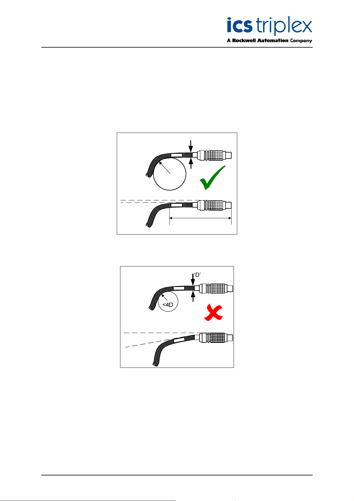
In order to maintain signal integrity and avoid cable damage it is important not to put lateral strain on
the LEMO connectors used on the TC-301, 302, 303, 314 and 322 series cables, or to bend the cables
in too small a radius. Undue pulling force when routing the cable should also be avoided.
he bend radius should not be less than 4 times the cable diameter and the cable should be parallel to
T
the connector for a minimum of 100mm before any bend.
‘D’
=4D
=100mm
Correct alignment of cable
Incorrect alignment of cable
Issue 13 Oct 11 PD-TC300 2
Page 3

Trusted
Issue Record
Issue
Number Date Revised by Technical CheckAuthorised by Modification
6 Sep-05 J W Clark Format
7 Dec 06 N Owens I Vince P Stock TC-305 Pin View
8 Apr 07 N Owens I Vince P Stock TC-310-02 added
9 Sep 07 N Owens I Vince P Stock TC-314-02 added
10 Dec 07 N Owens A Holgate P Stock Flame retardance
11 Jul 09 S Blackett A Holgate P Stock TC-322-02 Cable type
TM
Communication Cables TC300
added
12 April 10 S Blackett A Holgate P Stock Cable type change TC-
302-0x and TC-303-0x
13 Oct 11 Added
recommendations for
bend radius
Issue 13 Oct 11 PD-TC300 3
Page 4

Trusted
TM
Communication Cables TC300
Table of Contents
1. Communications Cable Type TC-301-0X ......................................................................................7
2. Communications Cable Type TC-302-0X ......................................................................................8
3. Communications Cable Type TC-303-0X ......................................................................................9
4. Communications Cable Type TC-304-01 .....................................................................................10
5. Communications Cable Type TC-305-0X ....................................................................................11
6. Communications Cable Type TC-306-02 .....................................................................................14
7. Communications Cable Type TC-308-02 .....................................................................................15
8. Communications Cable Type TC-310-02 .....................................................................................16
9. Communications Cable Type TC-31X-0X ....................................................................................17
10. Communications Cable Type TC-314-02 .....................................................................................19
11. Communications Cable Type TC-321-01 .....................................................................................20
12. Communications Cable Type TC-322-02 .....................................................................................21
Figures
Figure 1 Communications Cable Type TC-301-0X...................................................................................7
Figure 2 Communications Cable Type TC-302-0X...................................................................................8
Figure 3 Communications Cable Type TC-303-0X...................................................................................9
Figure 4 Communications Cable Type TC-304-01 .................................................................................10
Figure 5 Communications Cable Type TC-305-01 .................................................................................11
Figure 6 TC-305 Pin arrangement (view of outside of plug) ...................................................................13
Figure 7 Communications Cable Type TC-306-02 .................................................................................14
Figure 8 Communications Cable Type TC-308-01/02 ............................................................................15
Figure 9 Communications Cable Type TC-310-01/02 ............................................................................16
Figure 10 Communications Cable Type TC-312-02 ...............................................................................17
Figure 11 Communications Cable Type TC-314-02 ...............................................................................19
Figure 12 Communications Cable Type TC-321-01 ...............................................................................20
Figure 13 Communications Cable Type TC-322-02 ...............................................................................21
Tab le s
Table 1 TrustedTM Communications Cables .............................................................................................1
Table 2 TC-305-01 Pin Connections ......................................................................................................12
Table 3 TrustedTM Communications Cables ...........................................................................................17
Issue 13 Oct 11 PD-TC300 4
Page 5

Trusted
TM
Communication Cables TC300
Notice
The content of this document is confidential to ICS Triplex Technology Ltd. companies and their
partners. It may not be given away, lent, resold, hired out or made available to a third party for any
purpose without the written consent of ICS Triplex Technology Ltd.
his document contains proprietary information that is protected by copyright. All rights are reserved.
T
Microsoft, Windows, Windows 95, Windows NT, Windows 2000, and Windows XP are registered
trademarks of Microsoft Corporation.
The information contained in this document is subject to change without notice. The reader should, in
all cases, consult ICS Triplex Technology Ltd. to determine whether any such changes have been
made. From time to time, amendments to this document will be made as necessary and will be
distributed by ICS Triplex Technology Ltd.
Information in this documentation set may be subject to change without notice and does not represent
a commitment on the part of ICS Triplex Technology Ltd.
The contents of this document, which may also include the loan of software tools, are subject to the
confidentiality and other clause(s) within the Integrator Agreement and Software License Agreement.
No part of this documentation may be reproduced or transmitted in any form or by any means,
electronic or mechanical, including photocopying and recording, for any purpose, without the express
written permission of ICS Triplex Technology Ltd.
Disclaimer
The illustrations, figures, charts, and layout examples in this manual are intended solely to illustrate the
text of this manual.
The user of, and those responsible for applying this equipment, must satisfy themselves as to the
acceptability of each application and use of this equipment.
This document is based on information available at the time of its publication. While efforts have been
made to be accurate, the information contained herein does not purport to cover all details or variations
in hardware or software, nor to provide for every possible contingency in connection with installation,
operation, or maintenance. Features may be described herein which are present in all hardware or
software systems. ICS Triplex Technology Ltd. assumes no obligation of notice to holders of this
document with respect to changes subsequently made.
ICS Triplex Technology Ltd. makes no representation or warranty, expressed, implied, or statutory with
respect to, and assumes no responsibility for the accuracy, completeness, sufficiency, or usefulness of
the information contained herein. No warranties of merchantability or fitness for purpose shall apply
Issue 13 Oct 11 PD-TC300 5
Page 6

Trusted
TM
Communication Cables TC300
Revision and Updating Policy
All new and revised information pertinent to this document shall be issued by ICS Triplex Technology
Ltd. and shall be incorporated into this document in accordance with the enclosed instructions. The
change is to be recorded on the Amendment Record of this document.
Precautionary Information
WARNING
Warning notices call attention to the use of materials, processes, methods, procedures or limits which
must be followed precisely to avoid personal injury or death.
CAUTION
Caution notices call attention to methods and procedures which must be followed to avoid damage to
the equipment.
Notes:
Notes highlight procedures and contain information to assist the user in the understanding of the
information contained in this document
Warning
RADIO FREQUENCY INTERFERENCE
Most electronic equipment is influenced by Radio Frequency Interference (RFI). Caution should be
exercised with regard to the use of portable communications equipment around such equipment.
Signs should be posted in the vicinity of the equipment cautioning against the use of portable
communications equipment.
MAINTENANCE
Maintenance must be performed only by qualified personnel, otherwise personal injury or death, or
damage to the system may be caused.
Caution
HANDLING
Under no circumstances should the module housing be removed.
Associated Documents
Product Descriptions (PD) provide product specific information.
The Safety Manual contains the recommended safety requirements for the safety system design.
The PD8082B – Toolset Suite provides specific guidance on system configuration and application
generation.
The Operator and Maintenance Manual contains general guidelines on maintenance and diagnostic
procedures.
For technical support email: support@icstriplex.com
Issue 13 Oct 11 PD-TC300 6
Page 7
Trusted
TM
Communication Cables TC300
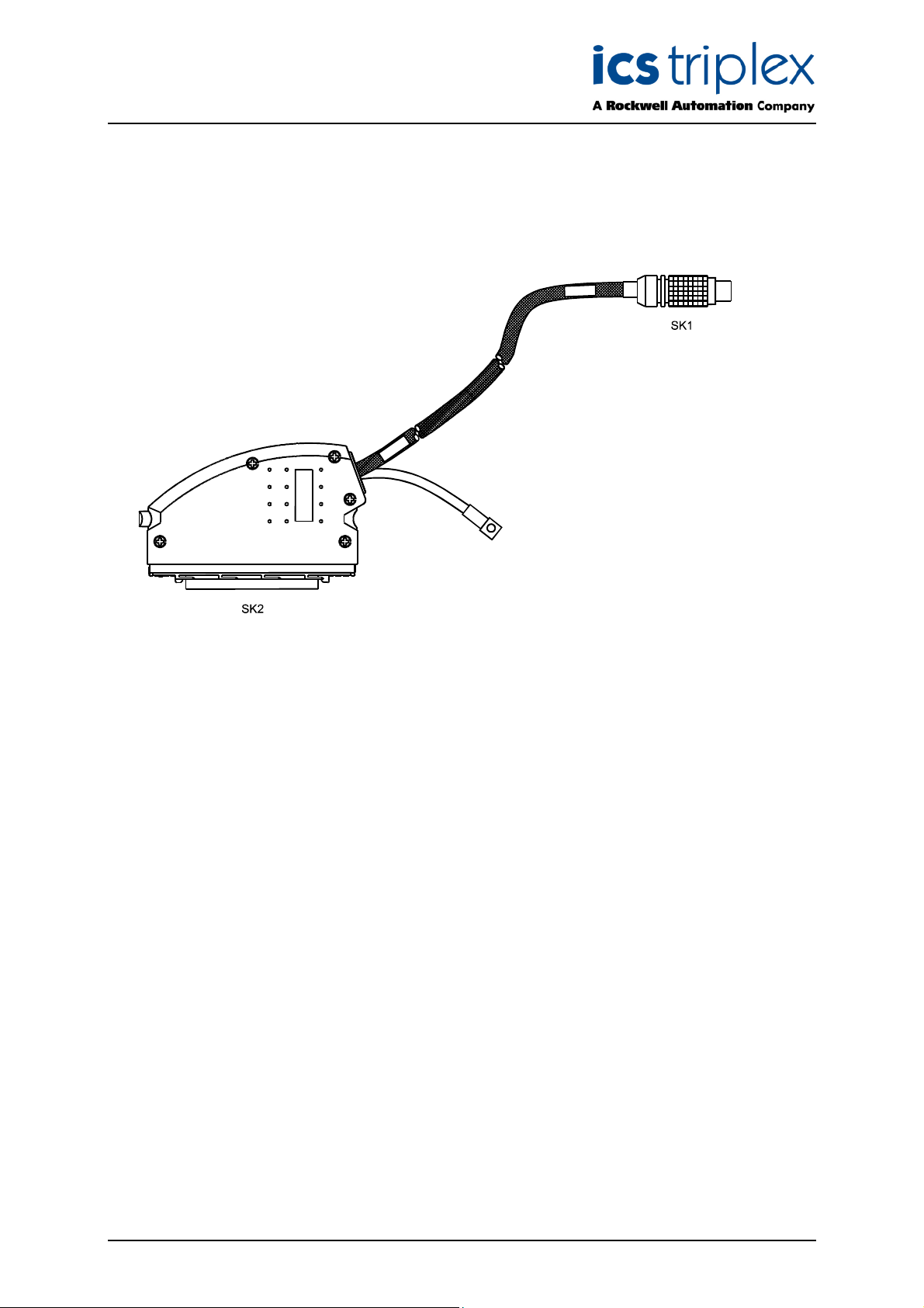
1. Communications Cable Type TC-301-0X
This type of Communications Cable is shown in Figure 1 below.
Figure 1 Communications Cable Type TC-301-0X
TM
This type of Trusted
Processor T8310 to the appropriate position on the Trusted
The Expander Processor end of the Cable (SKT2) is fitted with a 96-way type ‘C’ connector housed in
a double-width hood. The hood is fitted with an earth braid. The Expander Interface Adaptor end is
fitted with a 12-way LEMO plug.
The Cable is manufactured from either
• Cat 6 Plus, screened PVC sheath (TC-301-01)
• Cat 6 Plus, screened LSF/OH sheath (TC-301-02)
The ends of the sheathing are covered in heat shrink sleeving at one end (LEMO plug) and heated to
prevent fraying.
Maximum length 30m.
Communications Cable is designed to connect a TrustedTM TMR Expander
TM
Expander Interface Adaptor Unit T8312.
Issue 13 Oct 11 PD-TC300 7
Page 8

Trusted
TM
Communication Cables TC300
2. Communications Cable Type TC-302-0X
This type of Communications Cable is shown in Figure 2 below.
Figure 2 Communications Cable Type TC-302-0X
This type of Trusted
Trusted
The Expander Interface Adaptor end of the Cable (SKT1) is fitted with a 12-way LEMO plug. The Fibre
TX/RX end is fitted with three 4-way LEMO plugs.
The Cable is manufactured from either
• Cat 5, individually screened PVC sheath (TC-302-01)
• Cat 5, individually screened LSF/OH sheath (TC-302-02)
The ends of the sheathing are covered in heat shrink at both ends (LEMO plug) and heated to prevent
fraying.
TM
Expander Interface Adaptor Unit T8312 to a TrustedTM Fibre TX/RX Unit T8314.
TM
Communications Cable is designed to connect a specified position on a
Issue 13 Oct 11 PD-TC300 8
Page 9

Trusted
TM
Communication Cables TC300
3. Communications Cable Type TC-303-0X
This type of Communications Cable is shown in Figure 3 below.
Figure 3 Communications Cable Type TC-303-0X
TM
This type of Trusted
T8314 to a Trusted
The Expander Processor end of the Cable (SKT2) is fitted with a 96-way type ‘C’ connector housed in
a double-width hood. The hood is fitted with an earth braid. The Fibre TX/RX Unit end is fitted with
three 4-way LEMO plugs.
The Cable is manufactured from either
• Cat 5, individually screened PVC sheath (TC-303-01)
• Cat 5, individually screened LSF/OH sheath (TC-303-02)
The ends of the sheathing are covered in heat shrink sleeving and heated to prevent fraying.
Communications Cable is designed to connect a TrustedTM Fibre TX/RX Unit
TM
Expander Processor T8310 located in a remote TrustedTM Expander Chassis.
Issue 13 Oct 11 PD-TC300 9
Page 10

Trusted
TM
Communication Cables TC300
4. Communications Cable Type TC-304-01
This type of Communications Cable is shown in Figure 4 below.
Figure 4 Communications Cable Type TC-304-01
TM
This type of Trusted
(EWS) or PC to the front panel RS232 diagnostics port on either the Trusted
or Trusted
M
T
Communications Interface T8151.
The Cable is manufactured from 6-core Belden 9536 cable fitted with a 9-way ‘D’ type connector at one
end and a 6-way DIN connector at the other.
Communications Cable is designed to connect an Engineering Workstation
TM
TMR Processor T8110
Issue 13 Oct 11 PD-TC300 10
Page 11

Trusted
TM
Communication Cables TC300
5. Communications Cable Type TC-305-0X
This type of Communications Cable is shown in Figure 5 below.
Figure 5 Communications Cable Type TC-305-01
TM
This type of Trusted
communications ports available at the Trusted
The Communications Interface end of the Cable (SKT1) is fitted with a 78+2-way type ‘M’ connector
housed in a single-width hood. The hood is fitted with an earth braid. The other ends of the Cable
(8-off) are left free. Connectors conforming to user requirements are fitted. Only one, or other type of
the Ethernet ports may be used, not both simultaneously.
The Cable is manufactured from either
• Cat 5, screened PVC sheath (TC-305-01)
• Cat 6 Plus, screened LSF/OH sheath (TC-305-02)
The flying lead end of the sheathing is covered in heat shrink and heated to prevent fraying. 50H
coaxial cables is supplied for Ethernets E1 and E3.
Refer to Table 2 overleaf for details of pin connections, including screening.
Communications Cable is designed to provide connection to the
TM
Communications Interface T8151 via flying leads.
Issue 13 Oct 11 PD-TC300 11
Page 12

Trusted
TM
Communication Cables TC300
Connection Type SK1 Pin Function Core Colour
Ethernet 1
10 Base 2
E2
Ethernet 2
10 Base T
Ethernet 3
10 Base 2
E4
Ethernet 4
10 Base T
S1
Serial Port 1
RS232
RS422/485
S2
Serial Port 2
RS232
RS422/485
S3
Serial Port 3
RS422/485
S4
Serial Port 4
RS232
RS422/485
S1 50 OHM CO-AX INNER CORE E1
S1 GND OUTER SCREEN
21a TD+1 WH/OG
21b TD-1 OG
22a RD+1 WH/GN
22b RD-1 GN
SCREEN
S2 50 OHM CO-AX INNER CORE E3
S2 GND OUTER SCREEN
25a TD+2 WH/OG
25b TD-2 OG
26a RD+2 WH/BU
26b RD-2 BU
SCREEN
5a TXD1 RS232 WH/OG
6a RTS1 RS232 WH/BN
6b DTR1 RS232 WH/BU
6c RXD1 RS232 OG
7a CTS1 RS232 BN
7b DSR1 RS232 BU
8a RXB1 RS422/485 BN
8b RXA1 RS422/485 WH/BN
9a TXB1 RS422 WH/BU
9b TXAO RS422 BU
9c GND 0 RS232 SCREEN
4c to 29a LINK RS232
11a TXD2 RS232 WH/OG
11c RXD2 RS232 OG
12a RXB2 RS422/485 BN
12b RXA2 RS422/485 WH/BN
13a TXB2 RS422 WH/BU
13b TXA2 RS422 BU
13c GND 2 SCREEN
15a RXB3 RS422/485 WH/OG
15b RXA3 RS422/485 OG
16a TXB3 RS422 WH/BU
16b TXA3 RS422 BU
16c GND 3 SCREEN
18a RXB4 RS422/485 WH/OG
18b RXA4 RS422/485 OG
19a TXB4 RS422 WH/BU
19b TXA4 RS422 BU
19c GND4 SCREEN
Table 2 TC-305-01 Pin Connections
Issue 13 Oct 11 PD-TC300 12
Page 13

Trusted
TM
Communication Cables TC300
Figure 6 TC-305 Pin arrangement (view of outside of plug)
Issue 13 Oct 11 PD-TC300 13
Page 14

Trusted
TM
Communication Cables TC300
6. Communications Cable Type TC-306-02
This type of Communications Cable is shown in Figure 7 below.
Figure 7 Communications Cable Type TC-306-02
TM
This type of Trusted
Trusted
TM
Analogue or Digital Input module (40/60 Channel) and the I/O module occupying the
SmartSlot position in a Trusted
Communications Cable is designed to provide I/O connection between a faulty
TM
Controller or Expander Chassis.
The SmartSlot end of the Cable (SKT1) is fitted with a 96-way type ‘C’ connector housed in a
single-width hood. The hood is fitted with an earth braid. The faulty I/O module end is fitted with a
96-way type ‘R’ connector housed in a special-to-type plastic hood.
The Cable is manufactured from 96-way LSLH cable shrouded in Vidaflex sheathing. The ends of the
sheathing are covered in heat shrink sleeving and heated to prevent fraying.
Issue 13 Oct 11 PD-TC300 14
Page 15

Trusted
TM
Communication Cables TC300
7. Communications Cable Type TC-308-02
This type of Communications Cable is shown in Figure 8 below.
Figure 8 Communications Cable Type TC-308-01/02
TM
This type of Trusted
Trusted
TM
Digital Output module (40 Channel only) and the I/O module occupying the SmartSlot
position in a Trusted
Communications Cable is designed to provide I/O connection between a faulty
TM
Controller or Expander Chassis.
The SmartSlot end of the Cable (SKT1) is fitted with a 96-way type ‘C’ connector housed in a
single-width hood. The hood is fitted with an earth braid. The faulty I/O module end is fitted with a
96-way type ‘R’ connector housed in a special-to-type plastic hood.
The Cable is manufactured from 56-way LSLH (02) cable shrouded in Vidaflex sheathing. The ends of
the sheathing are covered in heat shrink sleeving and heated to prevent fraying.
Issue 13 Oct 11 PD-TC300 15
Page 16

Trusted
TM
Communication Cables TC300
8. Communications Cable Type TC-310-02
This type of Communications Cable is shown in Figure 9 below.
Figure 9 Communications Cable Type TC-310-01/02
TM
This type of Trusted
Trusted
TM
T8472 Digital Output module (16 Channel only) and the I/O module occupying the SmartSlot
position in a Trusted
Communications Cable is designed to provide I/O connection between a faulty
TM
Controller or Expander Chassis.
The SmartSlot end of the Cable (SKT1) is fitted with a 32-way type ‘D’ connector housed in a
single-width hood. The hood is fitted with an earth braid. The faulty I/O module end is fitted with a
32-way type ‘R’ connector housed in a special-to-type plastic hood.
The Cable is manufactured from 8-way and 3-way LSLH (02) cables shrouded in Vidaflex sheathing.
The ends of the sheathing are covered in heat shrink sleeving and heated to prevent fraying.
Issue 13 Oct 11 PD-TC300 16
Page 17

Trusted
TM
Communication Cables TC300
9. Communications Cable Type TC-31X-0X
This type of Communications Cable is shown in Figure 10 below.
Figure 10 Communications Cable Type TC-312-02
TM
This type of Trusted
between the Trusted
Trusted
TM
TMR Expander Processors T8310 in the TrustedTM Expander Chassis. There are three
Communications Cable is designed to provide the multi-drop connections
TM
Expander Interface modules T8311 in the TrustedTM Controller Chassis and the
variations of this cable as detailed in Table 3 below.
Cable Type Description
TC-311-01 Local Expansion Cable Assembly, 1 way
TC-311-02 Local Expansion Cable Assembly, 1 way
TC-312-01 Local Expansion Cable Assembly, 2 way
TC-312-02 Local Expansion Cable Assembly, 2 way
TC-313-01 Local Expansion Cable Assembly, 3 way
TC-313-02 Local Expansion Cable Assembly, 3 way
Table 3 TrustedTM Communications Cables
Issue 13 Oct 11 PD-TC300 17
Page 18

Trusted
TM
Communication Cables TC300
Each end of the Cable is fitted with a 96-way type ‘C’ connector housed in a double-width hood. Each
variation of the Cable is made up of a number of elements with SKT1 is all cases being connected to
the Trusted
TM
Expander Interface modules. The make-up of the Cables is detailed in below.
Cable No. of
Element Length
Elements
TC-311-01/2 1 SKT1 to SKT2 – 2m0
C-312-01/2 2 SKT1 to SKT2 – 2m0
T
SKT1 to SKT3 – 2m5
TC-313-01/2 3 SKT1 to SKT2 – 2m0
SKT1 to SKT3 – 2m5
SKT1 to SKT4 – 3m0
The Cable is manufactured from either
• Cat 6 Plus, screened PVC sheath (TC-302-01)
• Cat 6 Plus, screened LSF/OH sheath (TC-302-02)
Both ends of the sheathing are covered in heat shrink sleeving and heated to prevent fraying.
Issue 13 Oct 11 PD-TC300 18
Page 19

Trusted
TM
Communication Cables TC300
10. Communications Cable Type TC-314-02
This type of Communications Cable is shown in Figure 11 below.
Figure 11 Communications Cable Type TC-314-02
TM
This type of Trusted
T8312 Trusted
connection between a Processor chassis and an expander chassis to a total of up to 36m. Three TC314-02 cables are required per expander chassis, thus it also provides the chance for diverse routing.
The cables link between a TC-302-02 cable and a TC-303-02 cable, as if an electrical version of a fibre
optic extension.
The cable is fitted with two identical 4-way round connectors. At the Processor chassis end, the
connector fits one plug on a TC-302-02 cable, usually used to connect a T8312 Expander Interface
Adapter to T8314 fibre optic converters. At the expander chassis end, the connector fits one plug on a
TC-303-02 cable, usually used to connect the other end of a fibre optic connection to the expander
chassis. Each TC-314-02 cable carries one transmit/receive balanced communications pair between
the expander interface and the expander processor. Three TC-314-02 cables are required in the
triplicated connection
TM
Communications Cable is designed to connect communications between a
Processor Interface Adapter and a T8310 Expander Processor, to extend electrical
The Cable is manufactured from a length of 4 pair Cat6 or Cat7 LSOH screened cable. The ends of
the sheathing are taken inside a bend relief cable boot at each end. The cable can be supplied to a
maximum length of 30m and the total cable length (TC-302-02 – TC-314-02 – TC-303-02) can not
exceed 36m.
Issue 13 Oct 11 PD-TC300 19
Page 20

Trusted
TM
Communication Cables TC300
11. Communications Cable Type TC-321-01
This type of Communications Cable is shown in Figure 12 below.
Figure 12 Communications Cable Type TC-321-01
TM
This type of Trusted
T8160 TMR Interface Module and one or more Regent I/O chassis. This creates a system with a
Trusted
The T8160 end of the cable is fitted with two 96-way type ‘C’ connectors housed in a double-width
hood. The hood is fitted with an earth braid. The Regent Chassis end is fitted with three sockets
designed to link onto three TMR Interface cables to the Regent chassis.
The Cable is manufactured from 96-way LSLH cable shrouded in Vidaflex sheathing. The ends of the
sheathing are covered in heat shrink sleeving and heated to prevent fraying.
TM
processor (and other TrustedTM modules) and Regent I/O modules.
Communications Cable is designed to connect communications between a
Issue 13 Oct 11 PD-TC300 20
Page 21

Trusted
TM
Communication Cables TC300
12. Communications Cable Type TC-322-02
This type of Communications Cable is shown in Figure 13 below.
Figure 13 Communications Cable Type TC-322-02
This type of Trusted
Trusted
Triguard chassis or a 8162 CS300 Bridge Module in a CS300 chassis. This creates a system with a
Trusted
M
T
Expander Interface module T8311 and a 8161 SC300e Bridge Module in a SC300e
TM
processor (and other TrustedTM modules) and Triguard or CS300 I/O modules.
The cable is fitted with two 12-way round connectors. At the Trusted
on the T8312 Interface Adapter, which mounts on the Trusted
Interface. At the Triguard or CS300 end, the right-angled connector fits an interface card supplied with
the cable, which fits the three PCB header connectors on the Triguard or CS300 chassis backplane.
For more information, please refer to PD-8161 and PD-8162
TM
Communications Cable is designed to connect communications between a
M
T
TM
end, the connector fits a socket
chassis behind the P8311 Expander
The Cable is manufactured from two lengths of 8 way screened cable shrouded in Vidaflex sheathing.
The ends of the sheathing are taken inside a bend relief cable boot at each end.
Issue 13 Oct 11 PD-TC300 21
Page 22

 Loading...