

Page 1
Triguard SC300E
TBT
Bus Terminator
INTRODUCTION
(TBT
Issue 2
October 2005
)
PURPOSE
The Bus Terminator (TBT) is a passive end
TBT is to minimise line ringing and pulse reflections in order to eliminate transmission data
erro
rs.
This document is intended to provide a general understanding of the TBT sufficient to enable
basic
maintenance procedures to be effected in the field.
-of-
line I/O data bus terminator. The purpose of the
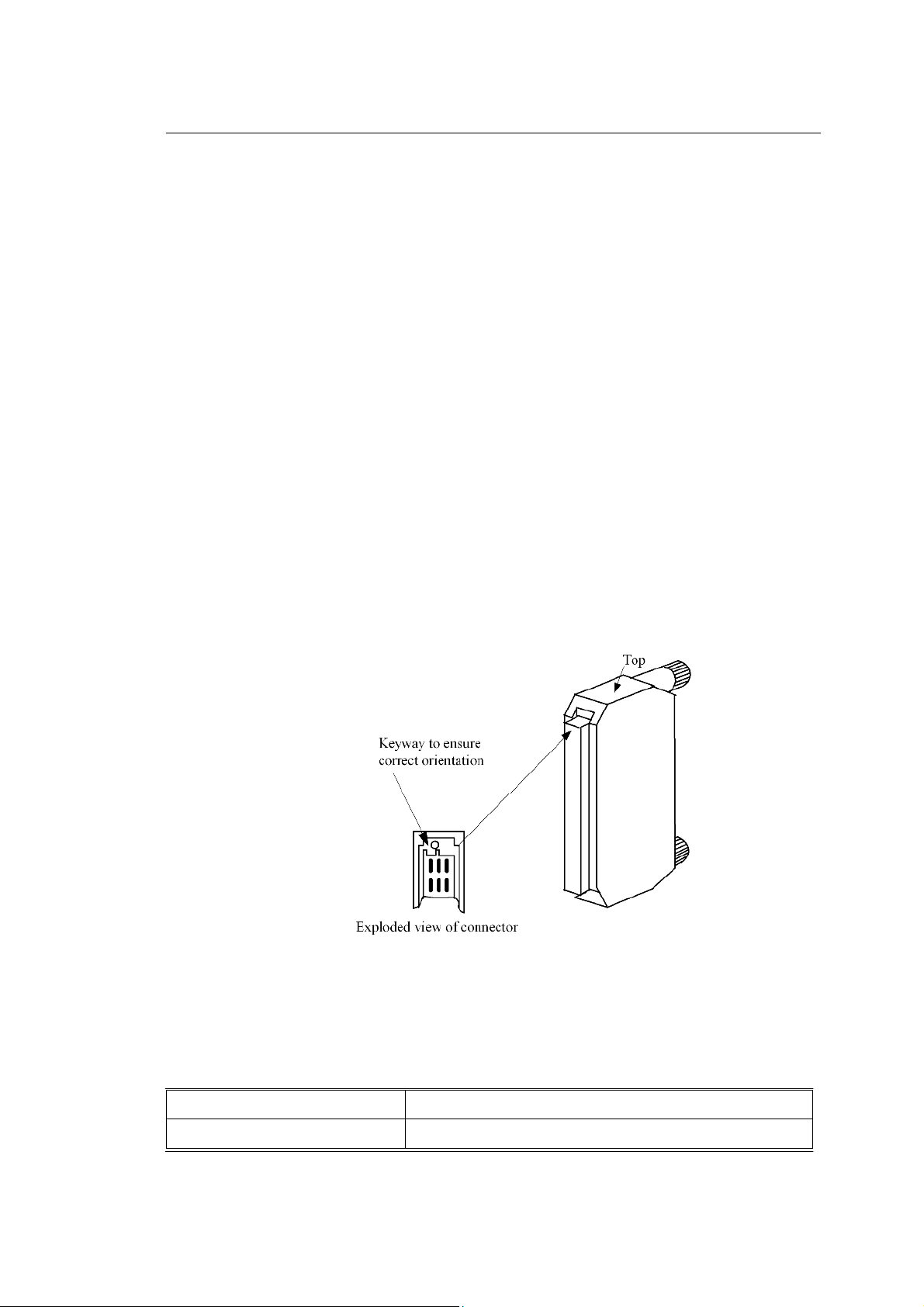
Figure 1-1. TBT Bus terminator-General view
ASSOCIATED DOCUMENTATION
008-5115
Reference No
TBA Bus Expansion Adaptor User Manual
008-5217
Title
Page 2

2
TBT
October
2005–
Issue 2
Triguard
SC300E
Page 3

TBT
October
2005–Issue 2
3
SPECIFICATION
Model
Triguard
TBT
SC300E TBT Bus Terminator
Connector
Overall size (mm)
Overall size (inches)
Weight (per set of three)
ENVIRONMENTAL SPECIF
The maximum ambient temperature measured at the hottest point within the Triguard system
shall
Temperature operating:
Temperature
Humidity
Certification:
General Certification: Ref. SC300E TMR Product Guide (ref 008-5209)
ICATIONS
not be greater than 60 degrees centigrade.
storage:
+5°C to +60°C
-
25°C to +70°C
5% to 95% non-condensing at ambient <40°C
DIN41612 style ‘c’ 64-way
100H x 18W x 40D
3.94H x 0.7W x 1.57D
0.21kg
TRANSPORT AND HANDLING
The TBT must be transported and stored in its original packing material, which should be
retained for this purpose.
Page 4

4
TBT
October
2005–
Issue 2
Triguard
SC300E
TECHNICAL DESCRIPTIO
N
PHYSICAL
The TBT bus terminator consists of a DIN41612 connector with two fixing screws to fit to the
bus
expansion adaptors (TBA) fitted to the SC300E chassis.
THEORY OF OPERATION
If the SC300E chassis are arranged with the MPPs at one end of the bus then the TBTs must
be fitted at at the other end of the bus as shown in Figure 2-1
the bus is arranged with the MPPs in the middle of the bus then TBTs will be required at both
If
ends
of
the bus as shown in Figure 2-2
.
.
Figure 2-1 TBT termination diagram -
Main chassis at one end of the bus
Page 5

TBT
October
2005–Issue 2
5
Triguard
SC300E TBT Bus Terminator
Figure 2-2 TBT termination diagram -
Main chassis at not an end of the bus
Page 6

6
TBT
October
2005–
Issue 2
Triguard
SC300E
SERVICING
SCOPE
System repair is by replacement of the faulty device. Faulty devices are not repairable in the
field. They should be re
repair.
The fitting or removal of these devices on a running system could result in a plant shutdown.
placed by a serviceable spare and the faulty device returned to for
WARNING 1
FUNCTIONAL TESTING
There are no functional tests for this device available on-line.
NOTE
Continued inexplicable errors occurring on one channel may mean that the TBT
is faulty. This fact can only be established if a replacement cures the problem
.
Page 7

TBT
October
2005–Issue 2
7
Triguard
SC300E TBT Bus Terminator
SERVICE SUPPORT
SPARE PARTS
Spare parts and technical advice can be obtained from your local area offices
.
 Loading...