

Page 1

Triguard SC300E
FS2)
place
be
TAI16AIR
INTRODUCTION
PURPOSE
16-Channel Analogue Input
Termination Card
(TAI16AIR
Issue 5
October 2005
)
The TAI16AIR termination card enables the connection of up to 16 loop-current, field devices to
the channel inputs of a SC300E Analogue Input Module. The fiel
individual
and
This document is intended to provide a general understanding of the function of the termination
card,
ASSOCIATED DOCUMENTATION
Reference No
008-5103
008-5104
cables to screw terminals on the card, which is in turn connected, via multicore cable
DIN41612 connectors, to the backplane of the SC300E chassis.
sufficient to enable basic maintenance operations to be effected in the field.
Title
MAI32*AD 32-Channel Analogue Input Module User Manual
PDD24 Power Distribution Panel User Manual
d devices are connected via
SPECIFICATION
Model
TAI16AIR
Power supply inputs
No. of analogue inputs
Nominal field supply voltage
Has two separate connectors (FS1 and
for redundant dc power supplies. The positive
supplies
diodes. Where auctioneering takes
outside the card, the required power may
supplied via a single connector.
16
24Vdc
008-5155
feed a common bus via auctioneering
Page 2

2
TAI16AI
R
October
2005–
Issue 5
Triguard
SC300E
Model
TAI16AIR
Maximum field supply voltage
Current rating
Fuse in each positive line to field
Fuse in each negative line to field
Terminating resistor
Chassis cable connector
Field cable connector
Fuse blown indication
Transient suppression
34 way DIN41612
33Vdc
50mA per channel
1A, fast acting, indicating
63mA, fast acting
250 ohm, 0.5W, 0.1% high stability, 3ppm/°C
Screw terminal to suit 2.5mm2wire (16 AWG)
Local: Fuse blown LED (one per card)
Remote: Fuse blown alarm output (PL1) –
be connected to Fuse blown LED on Power
Distribution Panel (PDD24).
A transient suppressor clamps the voltage
across
each input pair as follows (the device
is bi-directional):
14Vdc to 17Vdc @ 1mA (max current for
continuous overload)
27Vdc @ 176A max peak pulse current for 8
to 20Bs
can
Safety ground terminal TS1
Overall size (mm)
Overall size (inches)
Weight
M3 threaded bush provision for a ring terminal.
Allows the common 0V supply bus to be
grounded via a 10k ohm resistor. Prevents the
channels from ‘floating’ when the I/O module
is removed from the chassis.
162L x 125W x 107H
6.4L x 4.9W x 4.2H
0.36kg
Page 3

TAI16AI
R
October
2005–
Issue 5
3
Triguard SC300E
TAI16AIR
16-Channel A/I Termination Card
ENVIRONMENTAL SPECIF
The maximum ambient temperature measured at the hottest point within the Triguard system
shall
not be greater than 60 degrees centigrade.
Temperature operating:
Temperature
Humidity:
EMC/RFI
Vibration/Shock:
Certification:
General Certification: Ref. SC300E TMR Product Guide (ref 008-5209).
storage:
Immunity:
ICAT
IONS
0 to 60°C
-
25°C to +70°C
5% to 95% non-condensing at ambient <40°C
Tested and certified to IEC 1131-Part 2 1994
Tested and certified to IEC 1131-Part 2 1994
TRANSPORT AND HANDLING
The t
ermination card must be transported and stored in its original packing material which
should be retained for this purpose.
Page 4
4
TAI16AI
R
October
2005–
Issue 5
Triguard
SC300E
TECHNICAL DESCRIPTIO
N
PHYSICAL
The TAI16AIR termination card comprises a PCB assembly mounted in a moulded carrier that
can be snapped on to
chassis
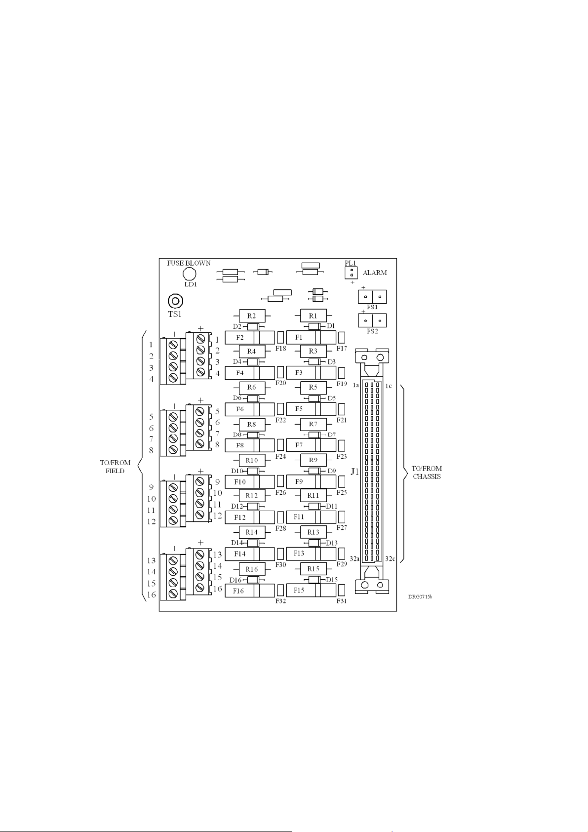
Field connections are made to screw terminals. Figure 2-1 shows the main components on
the card and Figure 2-2 shows the card, with the DIN connector attached, mounted on rail EN
50022 type NS 35/5.
backplane is via a multicore cable terminated at each end by a DIN 41612 connector.
all commercially available styles of DIN mounting rail. Connection to the
Figure 2-1 General view and component layout
Page 5

TAI16AI
R
October
2005–
Issue 5
5
Triguard SC300E
TAI16AIR
16-Channel A/I Termination Card
Figure 2-2 Leading dimensions and mounting schematic
Page 6

6
TAI16AI
R
October
2005–
Issue 5
Triguard
SC300E
EXTERNAL CONNECTIONS
Fixed Terminal
Chassis connector J1
Field terminals 1 to 16(+) and 1 to 16(
Field power supply inputs FS1 and FS2
Alarm output PL1
Ground terminal TS1
Connector, 34-way, DIN41612, female
-)
Screw terminals to suite 2.5mm2wire
(16AWG)
Header, 2-way, Molex Minifit Jr
Head
Provision for M3 ring terminal
er, 2-way, Molex KK
Details
THEORY OF OPERATION
The termination card circuit comprises 16 channels each fused at 1A with a fast acting,
indicating fuse. Figure 2-3 shows the connections for Channel 1, all other channels are
identical.
The current loop field device is connected across the screw terminals 1(+) and 1(-) and
supplied
device re-enters the termination card and develops a voltage across the 250 ohm precision
resistor R1. This metered voltage is applied, via J1/2a and J1/2c, to one of the channels of a 0
5V Analogue Input Module. Use of the precision resistor allows the output voltage to be applied
to more than one An
can
the
with a nominal 24V via the indicating fuse F1. The 0-20mA loop current from the field
alogue Input Module without sharing the loop current so that two modules
be
connected in parallel for ‘hot repair’ redundancy. D1 is a transient suppressor to protect
module input against the effects of lightning strikes, etc. on the field equipment.
-
Any blown fuse lights the Fuse blown LED LD1 and also provides a remote Alarm output via
PL1/1 and 2.
Power for the circuit and for the field devices is from two independent supplies, nominally 24V,
at FS1 and FS2. The positive supply lines are auctioned via D17 and D18 to ensure even power
consumption. The common 0V line is connected to the negative side of all the module input
channels.
The common 0V line is also connected, via C1 and R20, to the M3 ring terminal TS1 which
should be connected to a s
to the chassis is disconnected.
uitable earth to prevent the channels floating if the multicore cable
Page 7

TAI16AI
R
October
2005–
Issue 5
7
Triguard SC300E
TAI16AIR
16-Channel A/I Termination Card
Figure 2-3 Functional diagram
Page 8

8
TAI16AI
R
October
2005–
Issue 5
Triguard
SC300E
Figure 2-4 Circuit diagram showing a single channel
Page 9

TAI16AI
R
October
2005–
Issue 5
9
Triguard SC300E
TAI16AIR
16-Channel A/I Termination Card
SUPPLEMENTARY INFORM
Function
Common field supply negative
Cable screen to chassis backplane earth
Ch10
Ch11
Ch1
Ch2
Ch3
Ch4
Ch5
Ch6
Ch7
Ch8
Ch9
ATION
DIN Connector J1 pins
+ve
2a
4a
6a
8a
10a
12a
14a
16a
18a
20a
22a
-
ve
1a
1c
2c
4c
6c
8c
10c
12c
14c
16c
18c
20c
22c
Ch12
Ch13
Ch14
Ch15
Ch15
24a
26a
28a
30a
32a
24c
26c
28c
30c
32c
Page 10

10
TAI16AI
R
October
2005–
Issue 5
Triguard
SC300E
SERVICING
SCOPE
No servicing is necessary
A blown fuse should only be replaced when the cause of the fault has been found and rectified.
The only repair possible to the termination card is the replacement of a blown fuse. If the card
is found to be faulty in any other respect it should be replaced and returned
CAUTION
fo
r repair.
Page 11

TAI16AI
R
October
2005–
Issue 5
11
Triguard SC300E
TAI16AIR
16-Channel A/I Termination Card
SERVICE SUPPORT
SPARE PARTS
Spare parts and technical advice can be obtained f
LIST OF SPARES
Circuit Ref
F1 to F16
F17 to F32
Part No
380-0013
380-1064
rom your local area offices.
1A, fast acting, indicating
63mA wire-ended
Details
 Loading...