

Page 1

AADvance Controller
Catalog Numbers T9110, T9300, T9310, T9401/2, T9431/2,
T9451, T9481/2
Configuration Guide Workbench R2.x Original Instructions
Page 2
AADvance Controller Configuration Guide Workbench R2.x
Important User Information
Read this document and the documents listed in the additional resources section about installation, configuration, and
operation of this equipment before you install, configure, operate, or maintain this product. Users are required to familiarize
themselves with installation and wiring instructions in addition to requirements of all applicable codes, laws, and standards.
Activities including installation, adjustments, putting into service, use, assembly, disassembly, and maintenance are required to
be carried out by suitably trained personnel in accordance with applicable code of practice.
If this equipment is used in a manner not specified by the manufacturer, the protection provided by the equipment may be
impaired.
In no event will Rockwell Automation, Inc. be responsible or liable for indirect or consequential damages resulting from the use
or application of this equipment.
The examples and diagrams in this manual are included solely for illustrative purposes. Because of the many variables and
requirements associated with any particular installation, Rockwell Automation, Inc. cannot assume responsibility or liability for
actual use based on the examples and diagrams.
No patent liability is assumed by Rockwell Automation, Inc. with respect to use of information, circuits, equipment, or software
described in this manual.
Reproduction of the contents of this manual, in whole or in part, without written permission of Rockwell Automation, Inc., is
prohibited.
Throughout this manual, when necessary, we use notes to make you aware of safety considerations.
WA RN I NG : Identifies information about practices or circumstances that can cause an explosion in a hazardous environment,
which may lead to personal injury or death, property damage, or economic loss.
ATTENTION: Identifies information about practices or circumstances that can lead to personal injury or death, property
damage, or economic loss. Attentions help you identify a hazard, avoid a hazard, and recognize the consequence.
IMPORTANT Identifies information that is critical for successful application and understanding of the product.
Labels may also be on or inside the equipment to provide specific precautions.
SHOCK HAZARD: Labels may be on or inside the equipment, for example, a drive or motor, to alert people that dangerous
voltage may be present.
BURN HAZARD: Labels may be on or inside the equipment, for example, a drive or motor, to alert people that surfaces may
reach dangerous temperatures.
ARC FLASH HAZARD: Labels may be on or inside the equipment, for example, a motor control center, to alert people to
potential Arc Flash. Arc Flash will cause severe injury or death. Wear proper Personal Protective Equipment (PPE). Follow ALL
Regulatory requirements for safe work practices and for Personal Protective Equipment (PPE).
2 Rockwell Automation Publication ICSTT-RM458D-EN-P - February 2021
Page 3

Preface
About This Publication
This software technical manual defines how to configure an AADvance®
controller
using the AADvance® Workbench software version 2.x to satisfy your system
operation and application requirements.
In no event will Rockwell Automation be responsible or liable for indirect or
consequential damages resulting from the use or application of this
equipment. The examples given in this manual are included solely for
illustrative purposes. Because of the many variables and requirements related
to any particular installation, Rockwell Automation does not assume
responsibility or reliability for actual use based on the examples and diagrams.
No patent liability is assumed by Rockwell Automation, with respect to use of
information, circuits, equipment, or software described in this manual.
All trademarks are acknowledged.
Disclaimer
It is not intended that the information in this publication covers every possible
detail about the construction, operation, or maintenance of a control system
installation. You should also refer to your own local (or supplied) system safety
manual, installation and operator/maintenance manuals.
Revision And Updating Policy
This document is based on information available at the time of its publication.
The document contents are subject to change from time to time. The latest
versions of the manuals are available at the Rockwell Automation Literature
Library under "Product Information" , “Critical Process Control & Safety
Systems".
Downloads
The product compatibility and download center is rok.auto/pcdc
Select the Find Downloads option under Download.
In the Product Search field enter "AADvance" and the AADvance option is
displayed.
Double-click on the AADvance option and the latest version is shown.
Select the latest version and download the latest version.
AADvance Release
.
This technical manual applies to AADvance system release 1.40
Rockwell Automation Publication ICSTT-RM458D-EN-P - February 2021 3
Page 4

Latest Product Information
For the latest information about this product review the Product Notifications
and Technical Notes issued by technical support. Product Notifications and
product support are available at the Rockwell Automation Support Center at
rok.auto/knowledgebase
.
At the Search Knowledgebase tab select the option By Product then scroll down
and select the ICS Triplex® product AADvance.
SM
Some of the Answer IDs in the Knowledge Base require a TechConnect
Support Contract. For more information about TechConnect Support Contract
Access Level and Features, click this link: Knowledgebase Document ID: IP622
- TechConnect Support Contract - Access Level & Features.
This will get you to the login page where you must enter your login details.
IMPORTANT A login is required to access the link. If you do not have an
account then you can create one using the "Sign Up" link at the
top right of the web page.
Purpose Of This Manual
Starting with a new panel and a software distribution DVD, this manual
explains how to install the AADvance Workbench. This manual defines the
process you must follow to configure your system. It includes background
information and step-by-step instructions for the following:
• Installing the software and setting up the software licensing
• Setting the controller IP Address and achieving communications with
the controller
• Defining the processor configuration
• Defining the application variables
• Configuring the I/O modules and channels
• Setting up MODBUS, CIP and SNCP
The instructions are based on using Release 2.1 of the AADvance Workbench
under the Windows XP operating system; other Windows operating systems
are supported - refer to the topic Chapter 2 "Planning the AADvance
Workbench Software Installation" for a full list of supported windows
operating systems.
This manual includes reference information about module status parameters
and I/O variables, to help you make a decision about which variable types to
use and full descriptions of the data values supplied by the I/O modules.
• If the information in this document does not agree with the applicable
project codes and standards, the system integrator must find a solution
for the mismatch.
• If AADvance is used for a safety function, the system integrator must
apply
4 Rockwell Automation Publication ICSTT-RM458D-EN-P - February 2021
Page 5

Who Should Use Manual
The data in this manual is written for system integrators who know about
building and setting up new systems. The system integrator must make sure
that the system complies with the local, national and international standards
for the application that AADvance is being used for.
Environmental Compliance
Rockwell Automation maintains current product environmental information
on its website at rok.auto/pec
.
Download Firmware, AOP, EDS, and Other Files
Summary of Changes
Download firmware, associated files (such as AOP, EDS, and DTM), and access
product release notes from the Product Compatibility and Download Center at
rok.auto/pcdc
.
This publication contains the following new or updated information. This list
includes substantive updates only and is not intended to reflect all changes.
Global changes
This table identifies changes that apply to all information about a subject in the
manual and the reason for the change. For example, the addition of new
supported hardware, a software design change, or additional reference
material would result in changes to all of the topics that deal with that subject.
Subject Reason
Applied latest publication template Marketing product change
New or enhanced features
This table contains a list of topics changed in this version, the reason for the
change, and a link to the topic that contains the changed information.
Additional Resources
Subject Reason
AADvance Release on page 3
Additional Resources on page 5
N on page 235 Removed NFPA 87.
proof test on page 236
Updated AADvance system release information.
Added reference to AADvance®-Trusted® SIS
Workstation software User Guide, publication
ICSTT-UM002.
Updated definition.
These documents contain additional information concerning related products
from Rockwell Automation.
Rockwell Automation Publication ICSTT-RM458D-EN-P - February 2021 5
Page 6

Resource Description
This technical manual defines how to safely apply AADvance controllers for a Safety
AADvance Controller Safety Manual, ICSTT-RM446
AADvance Controller System Build Manual, ICSTT-RM448
AADvance Controller Configuration Guide Workbench 1.x, ICSTT-RM405
AADvance-Trusted SIS Workstation Software User Guide, ICSTT-UM002
AADvance Controller OPC Portal Server User Manual, ICSTT-RM407
AADvance Controller PFH and PFDavg Data, ICSTT-RM449
AADvance Controller Solutions Handbook, ICSTT-RM447
AADvance Controller Troubleshooting and Maintenance Manual, ICSTT-RM406
Industrial Automation Wiring and Grounding Guidelines, publication 1770-4.1
Product Certifications website, rok.auto/certifications. Provides declarations of conformity, certificates, and other certification details.
Instrumented Function. It sets out standards (which are mandatory) and makes
recommendations to make sure that installations satisfy and maintain their required safety
integrity level.
This technical manual describes how to assemble a system, switch on and validate the
operation of your system.
This software technical manual defines how to configure an AADvance controller
using the AADvance Workbench software version 1.x to satisfy your system operation and
application requirements.
This publication provides how-to instructions for AADvance®-Trusted® SIS Workstation
software configuration and use.
This manual describes how to install, configure and use the OPC Server for an AADvance
Controller.
This document contains the PFH and PFD
examples on how to calculate the final figures for different controller configurations.
This technical manual describes the features, performance and functionality of the
AADvance controller and systems. It gives guidance on how to design a system to satisfy
your application requirements.
This technical manual describes how to maintain, troubleshoot and repair an AADvance
Controller.
Provides general guidelines for installing a Rockwell Automation industrial system.
Data for the AADvance Controller. It includes
avg
You can view or download publications at rok.auto/literature.
6 Rockwell Automation Publication ICSTT-RM458D-EN-P - February 2021
Page 7

Table of Contents
Preface . . . . . . . . . . . . . . . . . . . . . . . . . . . . . . . . . . . . . . . . . . . . . . . . . . . . . . . 3
About This Publication . . . . . . . . . . . . . . . . . . . . . . . . . . . . . . . . . . . . . . . . . . . 3
Download Firmware, AOP, EDS, and Other Files . . . . . . . . . . . . . . . . . . . . 5
Summary of Changes. . . . . . . . . . . . . . . . . . . . . . . . . . . . . . . . . . . . . . . . . . . . . 5
Additional Resources . . . . . . . . . . . . . . . . . . . . . . . . . . . . . . . . . . . . . . . . . . . . . 5
Table of Contents . . . . . . . . . . . . . . . . . . . . . . . . . . . . . . . . . . . . . . . . . . . . . . 7
Chapter 1
Quick Start Guide Creating Applications . . . . . . . . . . . . . . . . . . . . . . . . . . . . . . . . . . . . . . . . . . . 13
Make a First Application . . . . . . . . . . . . . . . . . . . . . . . . . . . . . . . . . . . . . . . . . 13
Program Enable Key. . . . . . . . . . . . . . . . . . . . . . . . . . . . . . . . . . . . . . . . . . . . . 15
Hardware Redundancy . . . . . . . . . . . . . . . . . . . . . . . . . . . . . . . . . . . . . . . . . . 16
Integrating the AADvance Controller with Other Systems. . . . . . . . . . . 16
Chapter 2
Software Installation and
Licensing
Planning the AADvance Workbench Software Installation . . . . . . . . . . 19
Upgrading from Release 1.x . . . . . . . . . . . . . . . . . . . . . . . . . . . . . . . . . . . . . . 20
Install the AADvance Workbench Software - Web Distribution . . . . . . 20
Install the AADvance Workbench Software - Full Product . . . . . . . . . . . 21
AADvance Workbench Licensing . . . . . . . . . . . . . . . . . . . . . . . . . . . . . . . . . 22
Set Up a Single User License or a Full License . . . . . . . . . . . . . . . . . . . . . . 23
Managing a Paid-for License . . . . . . . . . . . . . . . . . . . . . . . . . . . . . . . . . . . . . 23
Connecting the AADvance
Workbench to the Controller
Starting a Project and Defining
the Controller
Chapter 3
Controller IP Address. . . . . . . . . . . . . . . . . . . . . . . . . . . . . . . . . . . . . . . . . . . . 25
Allocating IP Addresses for Network Communications . . . . . . . . . . . . . 26
AADvance Discover Utility . . . . . . . . . . . . . . . . . . . . . . . . . . . . . . . . . . . . . . . 26
Configure the IP Address in the Controller . . . . . . . . . . . . . . . . . . . . . . . . 28
Configure the Controller Resource Number in the Controller . . . . . . . 31
Configure the IP Address of the Target Controller. . . . . . . . . . . . . . . . . . 33
System Security. . . . . . . . . . . . . . . . . . . . . . . . . . . . . . . . . . . . . . . . . . . . . . . . . 34
Workbench Access. . . . . . . . . . . . . . . . . . . . . . . . . . . . . . . . . . . . . . . . . . . 34
Integrating the AADvance Controller with Other Systems. . . . . . . . . . . 38
Network Firewall. . . . . . . . . . . . . . . . . . . . . . . . . . . . . . . . . . . . . . . . . . . . . . . . 38
Windows PC Firewall. . . . . . . . . . . . . . . . . . . . . . . . . . . . . . . . . . . . . . . . . . . . 40
Save and Load a Configuration . . . . . . . . . . . . . . . . . . . . . . . . . . . . . . . . . . . 40
Save a Configuration File. . . . . . . . . . . . . . . . . . . . . . . . . . . . . . . . . . . . . 40
Reload a saved Configuration File. . . . . . . . . . . . . . . . . . . . . . . . . . . . . 42
Replace an Application . . . . . . . . . . . . . . . . . . . . . . . . . . . . . . . . . . . . . . . . . . 42
Chapter 4
Reset Window Layout . . . . . . . . . . . . . . . . . . . . . . . . . . . . . . . . . . . . . . . . . . . 45
Help . . . . . . . . . . . . . . . . . . . . . . . . . . . . . . . . . . . . . . . . . . . . . . . . . . . . . . . . . . . 46
Rockwell Automation Publication ICSTT-RM458D-EN-P - February 2021 7
Page 8

Make a New Project . . . . . . . . . . . . . . . . . . . . . . . . . . . . . . . . . . . . . . . . . . . . . 47
Import Existing Project. . . . . . . . . . . . . . . . . . . . . . . . . . . . . . . . . . . . . . . . . . 52
Procedure to import an existing project. . . . . . . . . . . . . . . . . . . . . . . . 52
Procedure for Opening An Existing Project . . . . . . . . . . . . . . . . . . . . . . . . 54
To open a project from the Workbench. . . . . . . . . . . . . . . . . . . . . . . . . 54
To open a project from the Projects directory . . . . . . . . . . . . . . . . . . . 54
Equipment View . . . . . . . . . . . . . . . . . . . . . . . . . . . . . . . . . . . . . . . . . . . . . . . . 54
Communication View . . . . . . . . . . . . . . . . . . . . . . . . . . . . . . . . . . . . . . . . . . . 56
Application View. . . . . . . . . . . . . . . . . . . . . . . . . . . . . . . . . . . . . . . . . . . . . . . . 57
Add a New Controller. . . . . . . . . . . . . . . . . . . . . . . . . . . . . . . . . . . . . . . . . . . . 57
Configure the Controller Type. . . . . . . . . . . . . . . . . . . . . . . . . . . . . . . . . . . . 58
Configure Controller Properties . . . . . . . . . . . . . . . . . . . . . . . . . . . . . . . . . . 58
Controller Process Safety Time . . . . . . . . . . . . . . . . . . . . . . . . . . . . . . . . . . . 64
Configure the Top-level Process Safety Time. . . . . . . . . . . . . . . . . . . . . . . 65
Online Update . . . . . . . . . . . . . . . . . . . . . . . . . . . . . . . . . . . . . . . . . . . . . . . . . . 65
Archiving and Restoring Repository Projects . . . . . . . . . . . . . . . . . . . . . . 67
To archive a repository project . . . . . . . . . . . . . . . . . . . . . . . . . . . . . . . . 67
To restore a repository project . . . . . . . . . . . . . . . . . . . . . . . . . . . . . . . . 67
Processor Module Battery and Alarm. . . . . . . . . . . . . . . . . . . . . . . . . . . . . . 68
Configure the Processor Battery Alarm . . . . . . . . . . . . . . . . . . . . . . . . 68
Remote Fault Reset. . . . . . . . . . . . . . . . . . . . . . . . . . . . . . . . . . . . . . . . . . . . . . 68
Chapter 5
Declaring Project Variables About Variables . . . . . . . . . . . . . . . . . . . . . . . . . . . . . . . . . . . . . . . . . . . . . . . . . 71
Declare or Change Variables . . . . . . . . . . . . . . . . . . . . . . . . . . . . . . . . . . . . . 71
Properties for AADvance Project Variables. . . . . . . . . . . . . . . . . . . . . . . . . 72
Standard IEC 61131-3 Data Types. . . . . . . . . . . . . . . . . . . . . . . . . . . . . . . . . . 74
Built-in Data Types. . . . . . . . . . . . . . . . . . . . . . . . . . . . . . . . . . . . . . . . . . . . . . 74
Chapter 6
Setting Processor Variables Processor Variables . . . . . . . . . . . . . . . . . . . . . . . . . . . . . . . . . . . . . . . . . . . . . 77
To Wire a Processor Variable . . . . . . . . . . . . . . . . . . . . . . . . . . . . . . . . . . . . . 77
To Unwire a Processor Variable. . . . . . . . . . . . . . . . . . . . . . . . . . . . . . . . . . . 78
Status Variables. . . . . . . . . . . . . . . . . . . . . . . . . . . . . . . . . . . . . . . . . . . . . . . . . 78
Status Integers . . . . . . . . . . . . . . . . . . . . . . . . . . . . . . . . . . . . . . . . . . . . . . . . . 79
Number of Locked Input Variables . . . . . . . . . . . . . . . . . . . . . . . . . . . . 79
Number of Locked Output Variables. . . . . . . . . . . . . . . . . . . . . . . . . . . 79
Processor Module A Temperature . . . . . . . . . . . . . . . . . . . . . . . . . . . . . 80
Processor Module B Temperature . . . . . . . . . . . . . . . . . . . . . . . . . . . . . 80
Processor Module C Temperature . . . . . . . . . . . . . . . . . . . . . . . . . . . . . 80
Status Booleans. . . . . . . . . . . . . . . . . . . . . . . . . . . . . . . . . . . . . . . . . . . . . . . . . 80
System Health. . . . . . . . . . . . . . . . . . . . . . . . . . . . . . . . . . . . . . . . . . . . . . . 81
System Health Reset (Voted 1oo3) . . . . . . . . . . . . . . . . . . . . . . . . . . . . . 81
Dongle Detected (Voted) . . . . . . . . . . . . . . . . . . . . . . . . . . . . . . . . . . . . . 81
Processor Module A Online . . . . . . . . . . . . . . . . . . . . . . . . . . . . . . . . . . . 82
Processor Module B Online . . . . . . . . . . . . . . . . . . . . . . . . . . . . . . . . . . . 82
Processor Module C Online . . . . . . . . . . . . . . . . . . . . . . . . . . . . . . . . . . . 82
Processor Module A Health . . . . . . . . . . . . . . . . . . . . . . . . . . . . . . . . . . . 83
Processor Module B Health . . . . . . . . . . . . . . . . . . . . . . . . . . . . . . . . . . . 83
8 Rockwell Automation Publication ICSTT-RM458D-EN-P - February 2021
Page 9

Processor Module C Health . . . . . . . . . . . . . . . . . . . . . . . . . . . . . . . . . . . 83
Processor Module A 24 V1 Power Feed Health. . . . . . . . . . . . . . . . . . . 84
Processor Module B 24 V1 Power Feed Health. . . . . . . . . . . . . . . . . . . 84
Processor Module C 24 V1 Power Feed Health . . . . . . . . . . . . . . . . . . 84
Processor Module A 24 V2 Power Feed Health . . . . . . . . . . . . . . . . . . 85
Processor Module B 24 V2 Power Feed Health . . . . . . . . . . . . . . . . . . 85
Processor Module C 24 V2 Power Feed Health . . . . . . . . . . . . . . . . . . 85
Processor Module A Ready. . . . . . . . . . . . . . . . . . . . . . . . . . . . . . . . . . . . 85
Processor Module B Ready. . . . . . . . . . . . . . . . . . . . . . . . . . . . . . . . . . . . 86
Processor Module C Ready. . . . . . . . . . . . . . . . . . . . . . . . . . . . . . . . . . . . 86
Processor Module A NVRAM Battery Health. . . . . . . . . . . . . . . . . . . . 86
Processor Module B NVRAM Battery Health. . . . . . . . . . . . . . . . . . . . 87
Processor Module C NVRAM Battery Health. . . . . . . . . . . . . . . . . . . . 87
Control Variables . . . . . . . . . . . . . . . . . . . . . . . . . . . . . . . . . . . . . . . . . . . . . . . 87
Control Integers . . . . . . . . . . . . . . . . . . . . . . . . . . . . . . . . . . . . . . . . . . . . . . . . 88
AUX LED Colour . . . . . . . . . . . . . . . . . . . . . . . . . . . . . . . . . . . . . . . . . . . . 88
Allow Remote Fault Reset Most Significant Bits (MSB) . . . . . . . . . . 88
Allow Remote Fault Reset Least Significant Bits (LSB). . . . . . . . . . . 89
Control Booleans. . . . . . . . . . . . . . . . . . . . . . . . . . . . . . . . . . . . . . . . . . . . . . . . 89
Unlock All Locked Variables . . . . . . . . . . . . . . . . . . . . . . . . . . . . . . . . . . 89
Set System Health Alarm . . . . . . . . . . . . . . . . . . . . . . . . . . . . . . . . . . . . . 89
HART Pass-Through . . . . . . . . . . . . . . . . . . . . . . . . . . . . . . . . . . . . . . . . . 90
Perform Remote Fault Reset . . . . . . . . . . . . . . . . . . . . . . . . . . . . . . . . . . 90
Perform Remote Fault Join . . . . . . . . . . . . . . . . . . . . . . . . . . . . . . . . . . . 90
Real-Time Clock . . . . . . . . . . . . . . . . . . . . . . . . . . . . . . . . . . . . . . . . . . . . . . . . 91
RTC Processor Variables . . . . . . . . . . . . . . . . . . . . . . . . . . . . . . . . . . . . . . . . . 91
RTC Status Variables . . . . . . . . . . . . . . . . . . . . . . . . . . . . . . . . . . . . . . . . . . . . 91
RTC Status: Year. . . . . . . . . . . . . . . . . . . . . . . . . . . . . . . . . . . . . . . . . . . . . 91
RTC Status: Month . . . . . . . . . . . . . . . . . . . . . . . . . . . . . . . . . . . . . . . . . . 91
RTC Status: Day of Month . . . . . . . . . . . . . . . . . . . . . . . . . . . . . . . . . . . . 92
RTC Status: Hours . . . . . . . . . . . . . . . . . . . . . . . . . . . . . . . . . . . . . . . . . . . 92
RTC Status: Minutes . . . . . . . . . . . . . . . . . . . . . . . . . . . . . . . . . . . . . . . . . 92
RTC Status: Seconds . . . . . . . . . . . . . . . . . . . . . . . . . . . . . . . . . . . . . . . . . 93
RTC Status: Milliseconds . . . . . . . . . . . . . . . . . . . . . . . . . . . . . . . . . . . . . 93
RTC Program Variables. . . . . . . . . . . . . . . . . . . . . . . . . . . . . . . . . . . . . . . . . . 93
RTC Program: Year . . . . . . . . . . . . . . . . . . . . . . . . . . . . . . . . . . . . . . . . . . 93
RTC Program: Month . . . . . . . . . . . . . . . . . . . . . . . . . . . . . . . . . . . . . . . . 94
RTC Program: Day of Month. . . . . . . . . . . . . . . . . . . . . . . . . . . . . . . . . . 94
RTC Program: Hours. . . . . . . . . . . . . . . . . . . . . . . . . . . . . . . . . . . . . . . . . 94
RTC Program: Minutes. . . . . . . . . . . . . . . . . . . . . . . . . . . . . . . . . . . . . . . 95
RTC Program: Seconds. . . . . . . . . . . . . . . . . . . . . . . . . . . . . . . . . . . . . . . 95
RTC Program: Milliseconds. . . . . . . . . . . . . . . . . . . . . . . . . . . . . . . . . . . 95
RTC Control Variables . . . . . . . . . . . . . . . . . . . . . . . . . . . . . . . . . . . . . . . . . . . 96
RTC Control: RTC Write. . . . . . . . . . . . . . . . . . . . . . . . . . . . . . . . . . . . . . 96
RTC Control: RTC Read . . . . . . . . . . . . . . . . . . . . . . . . . . . . . . . . . . . . . . 96
RTC Control: Year . . . . . . . . . . . . . . . . . . . . . . . . . . . . . . . . . . . . . . . . . . . 97
RTC Control: Month . . . . . . . . . . . . . . . . . . . . . . . . . . . . . . . . . . . . . . . . . 97
RTC Control: Day of Month. . . . . . . . . . . . . . . . . . . . . . . . . . . . . . . . . . . 98
RTC Control: Hours. . . . . . . . . . . . . . . . . . . . . . . . . . . . . . . . . . . . . . . . . . 98
RTC Control: Minutes. . . . . . . . . . . . . . . . . . . . . . . . . . . . . . . . . . . . . . . . 99
Rockwell Automation Publication ICSTT-RM458D-EN-P - February 2021 9
Page 10

Configuring Timing and
Communications
RTC Control: Seconds. . . . . . . . . . . . . . . . . . . . . . . . . . . . . . . . . . . . . . . . 99
RTC Control: Milliseconds. . . . . . . . . . . . . . . . . . . . . . . . . . . . . . . . . . . . 99
To manually set the real-time clock . . . . . . . . . . . . . . . . . . . . . . . . . . . . . . 100
Chapter 7
Synchronizing the Controller Time . . . . . . . . . . . . . . . . . . . . . . . . . . . . . . 101
Choosing a Network Time Server . . . . . . . . . . . . . . . . . . . . . . . . . . . . 101
Using the Controller as an SNTP Client . . . . . . . . . . . . . . . . . . . . . . . 102
Using the Controller as an SNTP Server. . . . . . . . . . . . . . . . . . . . . . . 102
Using the Controller as an SNTP Client and Server. . . . . . . . . . . . . 103
Time Synchronization SNTP. . . . . . . . . . . . . . . . . . . . . . . . . . . . . . . . . 103
Configure the Controller as an SNTP Client . . . . . . . . . . . . . . . . . . . 103
Configure the Controller as an SNTP Server. . . . . . . . . . . . . . . . . . . 105
Using Serial Communications. . . . . . . . . . . . . . . . . . . . . . . . . . . . . . . . . . . 106
Serial Port Protocols . . . . . . . . . . . . . . . . . . . . . . . . . . . . . . . . . . . . . . . . 106
Configure the Serial Ports . . . . . . . . . . . . . . . . . . . . . . . . . . . . . . . . . . . 107
Serial Port Parameters . . . . . . . . . . . . . . . . . . . . . . . . . . . . . . . . . . . . . . 108
Chapter 8
Configuring the Controller I/O About Adding and Configuring I/O Modules. . . . . . . . . . . . . . . . . . . . . . . 111
Assign I/O Modules to a Configuration . . . . . . . . . . . . . . . . . . . . . . . 112
Resize a Group of Modules . . . . . . . . . . . . . . . . . . . . . . . . . . . . . . . . . . 116
Move a Module to a Different Slot . . . . . . . . . . . . . . . . . . . . . . . . . . . . 117
Remove an I/O Module. . . . . . . . . . . . . . . . . . . . . . . . . . . . . . . . . . . . . . 117
Enable I/O Online Update . . . . . . . . . . . . . . . . . . . . . . . . . . . . . . . . . . . 117
Change the I/O Configuration with an Online Update. . . . . . . . . . 120
About Wiring to and from I/O Channels . . . . . . . . . . . . . . . . . . . . . . 120
Configuring Digital Inputs. . . . . . . . . . . . . . . . . . . . . . . . . . . . . . . . . . . . . . 120
Threshold Values for Digital Inputs . . . . . . . . . . . . . . . . . . . . . . . . . . . . . . 121
Configuring Analogue Inputs . . . . . . . . . . . . . . . . . . . . . . . . . . . . . . . . . . . 124
Threshold Values for Analogue Inputs . . . . . . . . . . . . . . . . . . . . . . . . 125
Wire a Channel Variable to an Analogue Input . . . . . . . . . . . . . . . . 127
T9K_AI_COMPACT and T9K_AI_FULL. . . . . . . . . . . . . . . . . . . . . . . . 128
HART . . . . . . . . . . . . . . . . . . . . . . . . . . . . . . . . . . . . . . . . . . . . . . . . . . . . . . . . . 130
HART Pass-Through . . . . . . . . . . . . . . . . . . . . . . . . . . . . . . . . . . . . . . . . 133
Use FactoryTalk Asset Center with an Analogue Module . . . . . . . . 136
Configure HART Pass-Through Monitoring . . . . . . . . . . . . . . . . . . . 139
Configuring Digital Outputs . . . . . . . . . . . . . . . . . . . . . . . . . . . . . . . . . . . . 140
Variables for a Digital Output Module . . . . . . . . . . . . . . . . . . . . . . . . 140
Wire a Channel Variable to a Digital Output. . . . . . . . . . . . . . . . . . . 143
T9K_DO_COMPACT and T9K_DO_FULL. . . . . . . . . . . . . . . . . . . . . . 144
The State Variable for Digital Outputs . . . . . . . . . . . . . . . . . . . . . . . . 145
Protection for Digital Outputs . . . . . . . . . . . . . . . . . . . . . . . . . . . . . . . 145
Faulted State for Digital Outputs. . . . . . . . . . . . . . . . . . . . . . . . . . . . . 146
Configure the Channel Advanced Settings . . . . . . . . . . . . . . . . . . . . 147
Configuring Analogue Outputs. . . . . . . . . . . . . . . . . . . . . . . . . . . . . . . . . . 148
Configure the Channel Advanced Settings . . . . . . . . . . . . . . . . . . . . 149
T9K_AI_COMPACT and T9K_AI_FULL. . . . . . . . . . . . . . . . . . . . . . . . 150
10 Rockwell Automation Publication ICSTT-RM458D-EN-P - February 2021
Page 11

Chapter 9
Sharing Data between
ControlLogix and AADvance
Using AADvance for CIP . . . . . . . . . . . . . . . . . . . . . . . . . . . . . . . . . . . . . . . . 153
Connection Requirements of a Produced or Consumed Tag . . . . . . . . 154
Example: . . . . . . . . . . . . . . . . . . . . . . . . . . . . . . . . . . . . . . . . . . . . . . . . . . 154
Memory Considerations. . . . . . . . . . . . . . . . . . . . . . . . . . . . . . . . . . . . . 155
Data Types for CIP . . . . . . . . . . . . . . . . . . . . . . . . . . . . . . . . . . . . . . . . . . . . . 155
Setting Up Variables for CIP . . . . . . . . . . . . . . . . . . . . . . . . . . . . . . . . . . . . 156
Define the CIP Producer Link . . . . . . . . . . . . . . . . . . . . . . . . . . . . . . . . . . . 156
CIP and its Producer and Consumer Variables. . . . . . . . . . . . . . . . . 158
Define a CIP Consumer Link . . . . . . . . . . . . . . . . . . . . . . . . . . . . . . . . . . . . 159
With Status Produce and Consume Variables . . . . . . . . . . . . . . . . . . . . . 161
Obtaining the Connection Status for a Consumed Variable . . . . . . . . 161
AADvance Producer RunMode . . . . . . . . . . . . . . . . . . . . . . . . . . . . . . . . . . 163
About the RSLogix 5000 Configuration . . . . . . . . . . . . . . . . . . . . . . . . . . 164
Set the RSLogix UNICAST Configuration . . . . . . . . . . . . . . . . . . . . . 164
Chapter 10
Configuring MODBUS MODBUS Standards . . . . . . . . . . . . . . . . . . . . . . . . . . . . . . . . . . . . . . . . . . . 165
MODBUS Master Hardware and Physical Connections . . . . . . . . . . . . 165
Planning for MODBUS Master . . . . . . . . . . . . . . . . . . . . . . . . . . . . . . . . . . 166
MODBUS Master Command Set. . . . . . . . . . . . . . . . . . . . . . . . . . . . . . . . . 167
MODBUS Data Types and Addressing. . . . . . . . . . . . . . . . . . . . . . . . . . . . 167
MODBUS Message Scheduling . . . . . . . . . . . . . . . . . . . . . . . . . . . . . . . . . . 168
Configure MODBUS Addresses. . . . . . . . . . . . . . . . . . . . . . . . . . . . . . . . . . 170
Physical Connections for MODBUS RTU . . . . . . . . . . . . . . . . . . . . . . . . . 171
Physical Connections for MODBUS TCP . . . . . . . . . . . . . . . . . . . . . . . . . 172
MODBUS Names . . . . . . . . . . . . . . . . . . . . . . . . . . . . . . . . . . . . . . . . . . . . . . 172
Create a MODBUS Slave Object . . . . . . . . . . . . . . . . . . . . . . . . . . . . . . . . . 172
Configure a MODBUS Slave Object. . . . . . . . . . . . . . . . . . . . . . . . . . . 172
MODBUS Slave Exception Codes. . . . . . . . . . . . . . . . . . . . . . . . . . . . . 174
MODBUS Master . . . . . . . . . . . . . . . . . . . . . . . . . . . . . . . . . . . . . . . . . . . . . . 174
MODBUS Statistics . . . . . . . . . . . . . . . . . . . . . . . . . . . . . . . . . . . . . . . . . 175
Handling MODBUS Communication Errors . . . . . . . . . . . . . . . . . . 176
MODBUS Diagnostics . . . . . . . . . . . . . . . . . . . . . . . . . . . . . . . . . . . . . . 176
MODBUS Exception Responses . . . . . . . . . . . . . . . . . . . . . . . . . . . . . . 176
AADvance Objects for MODBUS Master . . . . . . . . . . . . . . . . . . . . . . 176
MODBUS Master Capacities . . . . . . . . . . . . . . . . . . . . . . . . . . . . . . . . . 177
Create a MODBUS Master Object. . . . . . . . . . . . . . . . . . . . . . . . . . . . . . . . 177
Configure for MODBUS RTU/TCP . . . . . . . . . . . . . . . . . . . . . . . . . . . 178
Create Links to MODBUS Slaves. . . . . . . . . . . . . . . . . . . . . . . . . . . . . . . . . 180
Configure a MODBUS Slave - General Tab . . . . . . . . . . . . . . . . . . . . 181
Configure a MODBUS Master Slave - Messages. . . . . . . . . . . . . . . . 183
Remove a MODBUS Object . . . . . . . . . . . . . . . . . . . . . . . . . . . . . . . . . . . . . 184
OPC . . . . . . . . . . . . . . . . . . . . . . . . . . . . . . . . . . . . . . . . . . . . . . . . . . . . . . . . . . 184
Configure OPC Parameters . . . . . . . . . . . . . . . . . . . . . . . . . . . . . . . . . . . . . 185
Sequence of Events (SOE). . . . . . . . . . . . . . . . . . . . . . . . . . . . . . . . . . . . . . . 187
Configure SOE Variables . . . . . . . . . . . . . . . . . . . . . . . . . . . . . . . . . . . . . . . 187
Rockwell Automation Publication ICSTT-RM458D-EN-P - February 2021 11
Page 12

Chapter 11
SNCP Bindings and the SNCP Network . . . . . . . . . . . . . . . . . . . . . . . . . . . . . . . . 191
Create a Binding Link . . . . . . . . . . . . . . . . . . . . . . . . . . . . . . . . . . . . . . . 192
SNCP Link Properties . . . . . . . . . . . . . . . . . . . . . . . . . . . . . . . . . . . . . . . 194
Bindings. . . . . . . . . . . . . . . . . . . . . . . . . . . . . . . . . . . . . . . . . . . . . . . . . . . 196
Configure Bindings. . . . . . . . . . . . . . . . . . . . . . . . . . . . . . . . . . . . . . . . . 197
SNCP Binding Error Variables . . . . . . . . . . . . . . . . . . . . . . . . . . . . . . . 198
Chapter 12
Peer-to-Peer Network Peer-to-Peer Features . . . . . . . . . . . . . . . . . . . . . . . . . . . . . . . . . . . . . . . . . . 201
Peer-to-Peer Configuration Process. . . . . . . . . . . . . . . . . . . . . . . . . . . . . . 201
Create a Peer-to-Peer Network . . . . . . . . . . . . . . . . . . . . . . . . . . . . . . . . . . 202
Peer-to-Peer Subnet Controller Configuration . . . . . . . . . . . . . . . . . . . . 204
Set up the Peer IP Addresses and Status Variable . . . . . . . . . . . . . . 206
Peer-to-Peer Data Blocks . . . . . . . . . . . . . . . . . . . . . . . . . . . . . . . . . . . . . . . 207
Configure Data Blocks. . . . . . . . . . . . . . . . . . . . . . . . . . . . . . . . . . . . . . . . . . 207
Configure Analog Input Blocks . . . . . . . . . . . . . . . . . . . . . . . . . . . . . . 210
Configure Digital Input Blocks. . . . . . . . . . . . . . . . . . . . . . . . . . . . . . . 213
Configure Analogue Output Blocks. . . . . . . . . . . . . . . . . . . . . . . . . . . 216
Configure Digital Output Blocks . . . . . . . . . . . . . . . . . . . . . . . . . . . . . 219
Peer-to-Peer Configuration Example 1 . . . . . . . . . . . . . . . . . . . . . . . . . . . 221
Peer-to-Peer Controller Setting Summary. . . . . . . . . . . . . . . . . . . . . 221
Peer-to-Peer Data Summary . . . . . . . . . . . . . . . . . . . . . . . . . . . . . . . . . 224
Appendix A
History of Changes . . . . . . . . . . . . . . . . . . . . . . . . . . . . . . . . . . . . . . . . . . . . . . . . . . . . . . . . . . . . . . . 227
Glossary . . . . . . . . . . . . . . . . . . . . . . . . . . . . . . . . . . . . . . . . . . . . . . . . . . . . 229
12 Rockwell Automation Publication ICSTT-RM458D-EN-P - February 2021
Page 13

Chapter 1
Quick Start Guide
Creating Applications The AADvance® Workbench is the software development environment for the
AADvance controller. It lets you make one comprehensive control solution and
then target parts of the solution to individual controllers. Interaction between
resources is automatic, eliminating the need to have different synchronous
schemes.
The AADvance Workbench supports the Function Block (FB), Structured Text
(ST) and Ladder Diagrams (LD) languages of IEC 61131-3. The Instruction List
(IL) language is not supported by Workbench 2.1 and the Sequential Function
Chart (SFC) language is not supported by Workbench 2.1 in a safety related
application. You can use one language or a combination of languages
depending on what is applicable to the application and your programming
style.
The AADvance Workbench runs on a Windows computer. You simulate and
test programs on the computer before downloading them to the controller. The
AADvance Workbench then works online to give you real-time monitoring,
online updates and other features. Connectivity between the AADvance
Workbench, the controller and between individual controllers, is through a
standard Ethernet network.
Make a First Application It only takes minutes to create the first application. If you have not already
installed and licensed the AADvance Workbench, do this now. Installation
instructions are provided in Chapter 2
Begin by creating a project and defining the type of hardware for the
controller:
1. Launch the software by clicking Start All Programs Rockwell
Automation AADvance 2.1 AADvance 2.1.
The application will open and display the following screen.
Default Start-Up Screen
Software Installation and Licensing.
Rockwell Automation Publication ICSTT-RM458D-EN-P - February 2021 13
Page 14
Chapter 1 Quick Start Guide
For subsequent use of the Workbench application, the layout for the screen
presented on start-up is the same as the view displayed on the previous closure
of the application. For further detail refer to Reset Window Layout
on page 45.
2. Create a new project (File New Project) and move to the Application
View, Communication View or Equipment View.
• the AADvance Workbench places a controller into the project
• the controller is named Controller1.
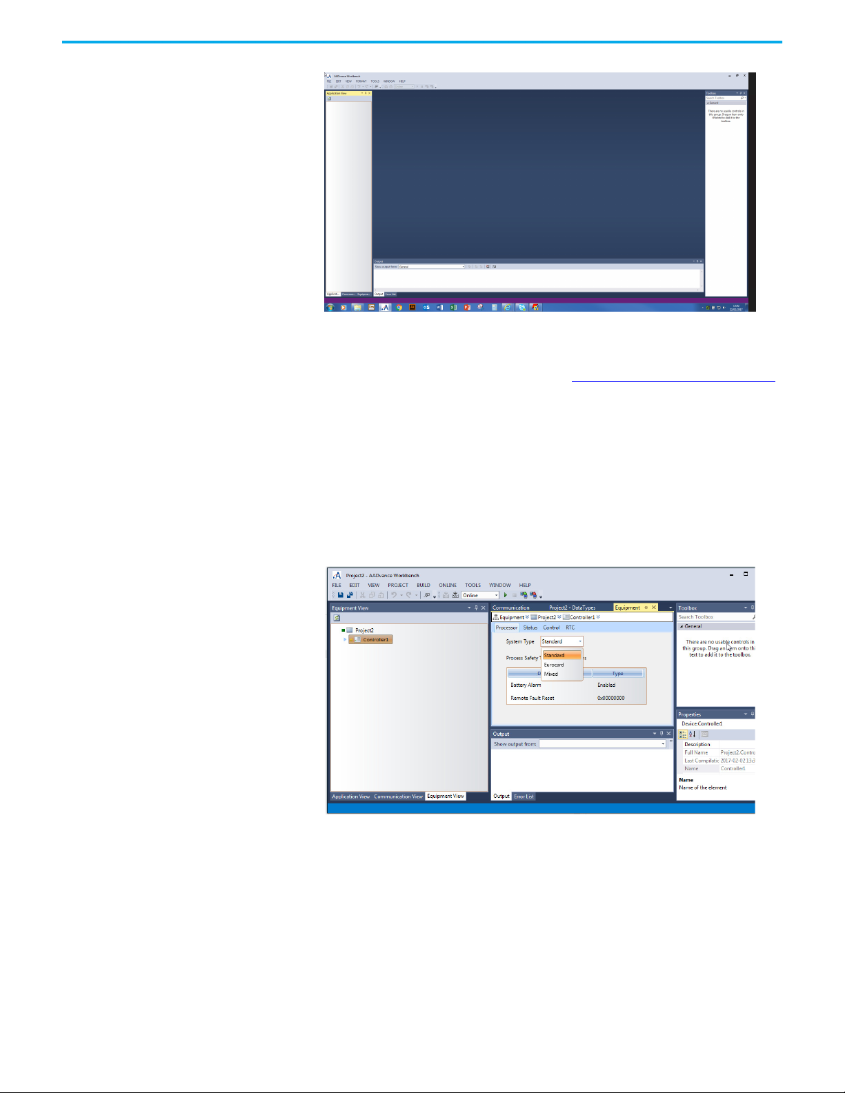
3. Select Equipment View Controller1 identify the system type of the
controller. The three options for system type are:
• Standard
• Eurocard
•Mixed.
4. If the project needs more controllers, use the contextual menu on the
project node (the first node in the tree) to add the controllers to the
project. Then identify the class of each new controller.
After having identified the controller class you can configure the controller
and place I/O modules with slots on the processor bus. Place input modules in
simplex, duplex and triplex arrangements, output modules in simplex and
duplex arrangements. The duplex and triplex arrangements use adjacent slots
in groups of two or three.
Proceed to the Application View, Communication View or Equipment View.
14 Rockwell Automation Publication ICSTT-RM458D-EN-P - February 2021
Page 15

Chapter 1 Quick Start Guide
IMPORTANT
1. Use a spreadsheet or equivalent tool to assign tag names to the variables
you want to use. If you chose structured variables for I/O channels, the
AADvance Workbench generates a set of other variable elements with the
same tag name for each element type.
2. Declare variables for I/O channels and module status parameters. An
extensive range of variable types is available including a set of structured
variables. You can subsequently add new variables if applicable.
3. Connect (wire) each I/O channel to variables to get input channel states
and set output data values.
4. Set up the serial ports, process safety time, and SNTP and MODBUS
services.
5. Allocate the IP addresses for communication with the AADvance
controllers and configure the network communications parameters.
The controller configuration must be exactly the same as the
hardware arrangement. If you change the physical arrangement
of the hardware, remember to change the Workbench
configuration to match the new arrangement.
Program Enable Key The standard AADvance controller has a program enable key which plugs into
the KEY connector on the 9100 processor base unit. When the key is removed,
the controller application is protected from unwanted changes. You must fit
the program enable key before performing a download to the application,
adjusting the application and setting or changing the controller IP address.
If the program enable key is not installed before performing a download to the
application, adjusting the application and setting or changing the controller IP
address will produce an error message. The error message will vary depending
on the application status, running or stopped.
Rockwell Automation Publication ICSTT-RM458D-EN-P - February 2021 15
Page 16
Chapter 1 Quick Start Guide
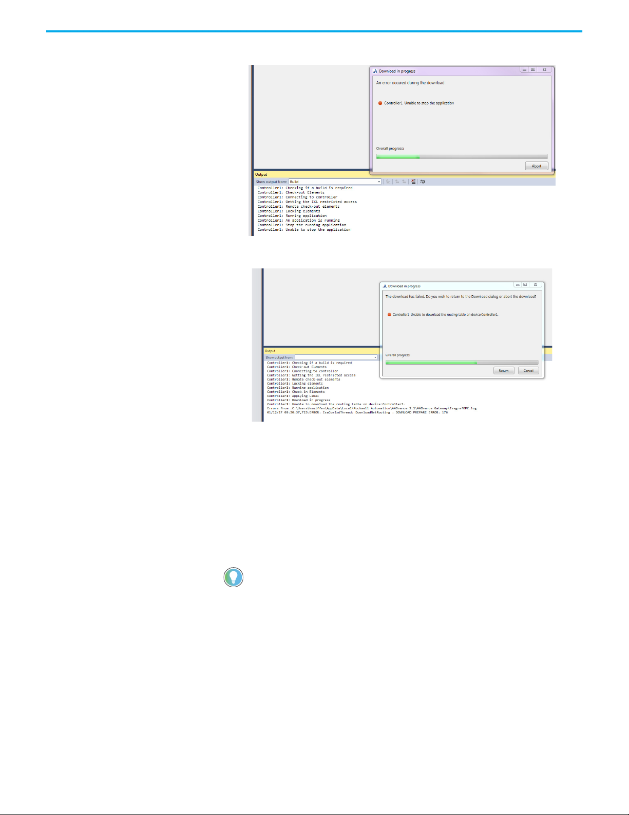
Figure 1 - With the application running the following error message occurs.
Figure 2 - With the application stopped the following error message occurs.
Hardware Redundancy You create hardware redundancy in the AADvance Workbench when you
identify the hardware configuration from the Equipment View. During the
allocation of I/O modules to empty slots, you have the option of adding two or
three modules. When you use the two or three option the AADvance
Workbench automatically allocates the modules to a group of adjacent slots.
The AADvance Workbench then only allows you to configure one set of I/O
channels to the group.
You do not need to define redundancy for AADvance processors. The
AADvance Workbench automatically connects to each processor when the
network connection is set up.
Integrating the AADvance
Controller with Other
The AADvance controller connects to existing control systems and plant
monitoring equipment. This connection enables a third-party control system
to read the state of sensors connected to the controller.
Systems
The connection interfaces are through the controller network ports and serial
ports, and use the following protocols:
• CIP™ over Ethernet/IP™
•Modbus RTU
• Open Modbus/TCP
16 Rockwell Automation Publication ICSTT-RM458D-EN-P - February 2021
Page 17

• OLE for Process Control (OPC).
Chapter 1 Quick Start Guide
IMPORTANT
In order to support the integrity of the AADvance system,
activation of network firewalls and Windows operating system
firewalls is strongly advised.
Rockwell Automation Publication ICSTT-RM458D-EN-P - February 2021 17
Page 18

Chapter 1 Quick Start Guide
Notes:
18 Rockwell Automation Publication ICSTT-RM458D-EN-P - February 2021
Page 19

Planning the AADvance Workbench Software Installation
Chapter 2
Software Installation and Licensing
The AADvance® Workbench software is a 32-bit application based on the
Microsoft Visual Studio Shell that runs on all common Windows platforms.
This chapter provides the instructions to install and license the AADvance
Workbench software.
IMPORTANT
The AADvance Workbench software uses the Microsoft Visual Studio 2010
with Service Pack 1. The installer automatically installs Microsoft Visual Studio
2010 Shell (isolated mode) and Microsoft .NET 4.0, but only if these are not
already installed on the computer. This reduces the time necessary for updates
of the AADvance Workbench, where the Microsoft Visual Studio and .NET are
already on the computer.
If you have not installed the AADvance Workbench software
before, read all of this section before starting the installation.
The specification of the computer where you install the software must have the
following specification, or better:
Operating system (32- bit or 64-bit):
• Microsoft Windows XP
•Windows Vista
•Windows 7
• Microsoft Windows Server 2003
• Microsoft Windows Server 2008.
Hardware:
•1.6 GHz CPU
• 1 GB RAM (32-bit) or 2 GB RAM (64-bit) (add 512 MB if running in a
virtual machine)
• DirectX 9 capable video card running at 1024 x 768 resolution display
•5,400 RPM hard disk
• 3 GB available hard disk space
• DVD drive or network connection, to read software distribution files
• Network port (10/100 Base T Ethernet), for communications with the
controller.
It is recommended that the computer has a 2.2 GHz or higher CPU; 1,024 MB
or more RAM, a 1,280 x 1,024 display and a 7,200 RPM or higher hard disk.
Rockwell Automation Publication ICSTT-RM458D-EN-P - February 2021 19
Page 20

Chapter 2 Software Installation and Licensing
It is also recommended that the hard disk has at least 10 GB free space. This
provides sufficient space to hold the distribution zip file, the unzipped source
files and the installed program files, and also sufficient space for Windows to
operate reasonably quickly. You can retrieve a lot of this space by deleting the
source files after finishing the installation.
Upgrading from Release 1.x If you are upgrading to AADvance 2.x from AADvance 1.x, and you mean to
migrate one or more existing projects to AADvance 2.x, do the following:
IMPORTANT
1. Make sure that the repository for the AADvance 1.x AADvance
Workbench is on a local disk drive. The AADvance 2.x Workbench does
not permit opening AADvance 1.x projects from a repository when no
local copy exists.
2. If the project is stored as only an AADvance 1.x archive, put back the
archive as a project in the AADvance 1.x Workbench.
3. Make sure that the AADvance 1.x project compiles fully.
4. Make sure that all users record all on-going modifications.
• When you open a project from an AADvance 1.x repository in
AADvance 2.x, the repository is upgraded to the current version and is
no longer available in the previous version.
• If you do not record all on-going modifications, the modifications
become local and cannot be integrated into the repository.
5. Write down the ID of each MODBUS Slave set up for Ethernet
communications. AADvance 2.x automatically assigns a value of 255 to a
MODBUS Slave ID for which Ethernet was specified.
6. Write down which Ethernet ports are assigned to CIP binding groups.
AADvance 2.x does not assign Ethernet ports to CIP binding groups, and
you have to specify Ethernet ports for individual groups after the
upgrade.
IMPORTANT
You must do these steps before installing AADvance 2.x.
The Instruction List (IL) language is not supported by Workbench
2.0 and the Sequential Function Chart (SFC) is not supported by
Workbench 2.0 in a safety related application.
Install the AADvance Workbench Software - Web Distribution
20 Rockwell Automation Publication ICSTT-RM458D-EN-P - February 2021
If you need to update an existing installation, use the web distribution version
of the AADvance Workbench software. The installation is smaller and quicker
than the full product because the Microsoft .NET Framework and Visual
Studio products which the software needs are already installed on the
computer.
IMPORTANT
The installation of the web distribution version takes about 10 minutes on a
computer with the recommended specification and will take longer if the
machine has less than 1,024 MB RAM.
To install the AADvance Workbench software (web distribution) do the
following:
If the AADvance Workbench has not been installed on the
computer, you must install the full product first. Following the
initial installation you can use the web distribution version to
update the installation.
Page 21

Chapter 2 Software Installation and Licensing
1. Log onto the computer using an account with administrator
permissions.
2. Close all programs and do not run them until the installation is
completed.
3. The software is supplied as a compressed archive. Make a local copy of
the archive on the hard disk. Then put the archive into a temporary folder
on the hard disk. Find the file named setup.exe and run it.
4. If there is an older version of the software on the machine, the software
will find it. Click Yes to update the existing version.
5. When the first window of the AADvance installer to opens, click Next.
6. Before proceeding, read the Release Notes.html file. This file is located in
the same folder as setup.exe.
7. Return to the installer window. The installer window shows the license
agreement. Accept the license agreement, click Next. The installation will
start.
8. If the installer offers you the opportunity to make a backup, click Yes.
Accept the default location for the backup files, and then wait for the
installer to make the backup. The installer displays a message showing
the location of the backup. Write down the location, then click OK.
9. If the computer has a repository of projects from AADvance release 1.x,
use a repository path which is different from the one used for AADvance
1.x.
10. Wait for the installer to finish, then click Finish.
11. The installation of the AADvance Workbench is now complete.
12. Select No, just reset settings, overwrite my current settings, click Next.
13. Select CurrentSettings.vssettings, click Finish.
Install the AADvance Workbench Software - Full Product
If you need to install the software on a computer where the software has not
been installed before, use the AADvance Workbench software full product.
Make sure that you have at least 10 GB free space on the local hard disk before
you install the software.
The full installation takes about 40 minutes on a computer having the
recommended specifications and will take a longer time (typically 3 or 4 hours)
if the machine has less than 1,024 MB RAM.
If the installation seems to have stopped (especially during the stages for
Microsoft Visual Studio), let the installer run for at least ten minutes before
investigating a possible problem.
IMPORTANT
To install the AADvance Workbench software (full product) do the following:
1. Log onto the computer using an account with administrator
permissions.
2. If you have Microsoft Visual Studio 2010 already installed on the
computer (this is likely only if you are a software developer), make sure
that it has Service Pack 1.
3. Close all programs and do not run them until the installation is
completed.
4. The software is supplied as a compressed archive and on a DVD:
You must install the Microsoft .NET Framework to use the
Workbench.
Rockwell Automation Publication ICSTT-RM458D-EN-P - February 2021 21
Page 22

Chapter 2 Software Installation and Licensing
• If the software has been supplied as a compressed archive (such as a
zip file), make a local copy of the archive on the hard disk. Then put the
archive into a temporary folder on the hard disk. Locate the file named
setup.exe and run it.
• If the software has been supplied on a DVD, place the disk into the
DVD-ROM drive and wait for the disk to Autorun. If the installer does
not start (typically because the Autorun feature has been disabled on
the computer), find the file named setup.exe on the DVD and run it.
5. Wait for the first window of the AADvance installer to open.
6. Before proceeding, read the Release Notes.html. This file is located in the
same folder as setup.exe.
7. Return to the installer window. The installer window shows the license
agreement. Accept the license agreement, click Next.
8. Accept the Complete setup type (this is the default), click Next.
9. If you are upgrading from AADvance release 1.x, use a repository path
which is different to the one used for AADvance 1.x.
10. If the Microsoft .NET Framework is not already installed on the
computer, the installer will ask for your permission to install it. Click
Install.
11. Wait for the Microsoft Visual Studio 2010 Isolated Shell English
installation to run.
12. Wait for the Microsoft Visual Studio 2010 Service Pack 1 Setup to run.
13. Wait for Help Viewer Verification process to run.
14. Wait for the installer to configure the software and do a module file
check.
15. Wait for the InstallShield Wizard Complete window to open, click
Finish.
16. The installer places a shortcut on the Windows desktop.
17. The installation of the AADvance Workbench is now complete. If the
software was supplied on a DVD, remove the DVD.
AADvance Workbench Licensing
The AADvance Workbench is licensed software. There are three types of
license: full, single controller and demo.
• The single controller license is applicable for applications which use only
one controller. The software features which add a second or subsequent
controller to the project are disabled, and you cannot open an existing
project which uses more than one controller.
• The full license supplies all of the features of the AADvance Workbench.
It is applicable for applications with one or more controllers.
• The demo license is a like a full license, but with a time limit. You can use
all of the features of the AADvance Workbench for up to 30 days after
first running the AADvance Workbench is first run.
A demo license is supplied free of charge for a first installation on a computer.
You change the demo license to a single controller license or a full license by
purchasing an unlock code from Rockwell Automation, and entering the code
into the software. When you use the demo license, the AADvance Workbench
displays a Demo License window each time you try to open a project. The
window includes the contact details at Rockwell Automation required for
purchasing a license.
If you try to use the demo license for more than 30 days, the license expires.
You cannot open a project or create a new one until you purchase a license.
22 Rockwell Automation Publication ICSTT-RM458D-EN-P - February 2021
Page 23

Chapter 2 Software Installation and Licensing
Set Up a Single User License or a Full License
Managing a Paid-for License
You have to set up a single user license or a full license if you want to use the
AADvance Workbench after the demo license expires.
To set up a single user license or a full license, do the following:
1. Click Help Licensing, a Licensing window is displayed.
2. Copy the three user codes into an email stating the type of license
necessary (this is a single user license or a full license) and send the email
to keymaster@ra.rockwell.com or keymaster@icstriplex.com.
3. Rockwell Automation will reply to the email and will send you two
registration keys.
• These registration keys are only valid for the provider user codes.
These codes might have changed since the last time they were
displayed, if they did you will need to resend the new user codes.
4. Enter the registration keys into the Licensing window, click Validate.
5. The software license can now be used.
6. Repeat this procedure on each other computer where you have installed
and want to use the AADvance Workbench.
After purchasing a paid-for license, the license persists through all Workbench
updates and uninstall/re-install operations on the same computer.
A paid-for license is specific to the computer for which it is purchased. If you
need to move the license to a different computer, or you change the hard disk
drive, contact Rockwell Automation for advice.
Rockwell Automation Publication ICSTT-RM458D-EN-P - February 2021 23
Page 24

Chapter 2 Software Installation and Licensing
Notes:
24 Rockwell Automation Publication ICSTT-RM458D-EN-P - February 2021
Page 25
Chapter 3
Connecting the AADvance Workbench to the
Controller
The AADvance® system uses Internet Protocol (IP) for communication/data
transfer between the controller and the AADvance Workbench. This chapter
describes how to connect the AADvance Workbench to the controller.
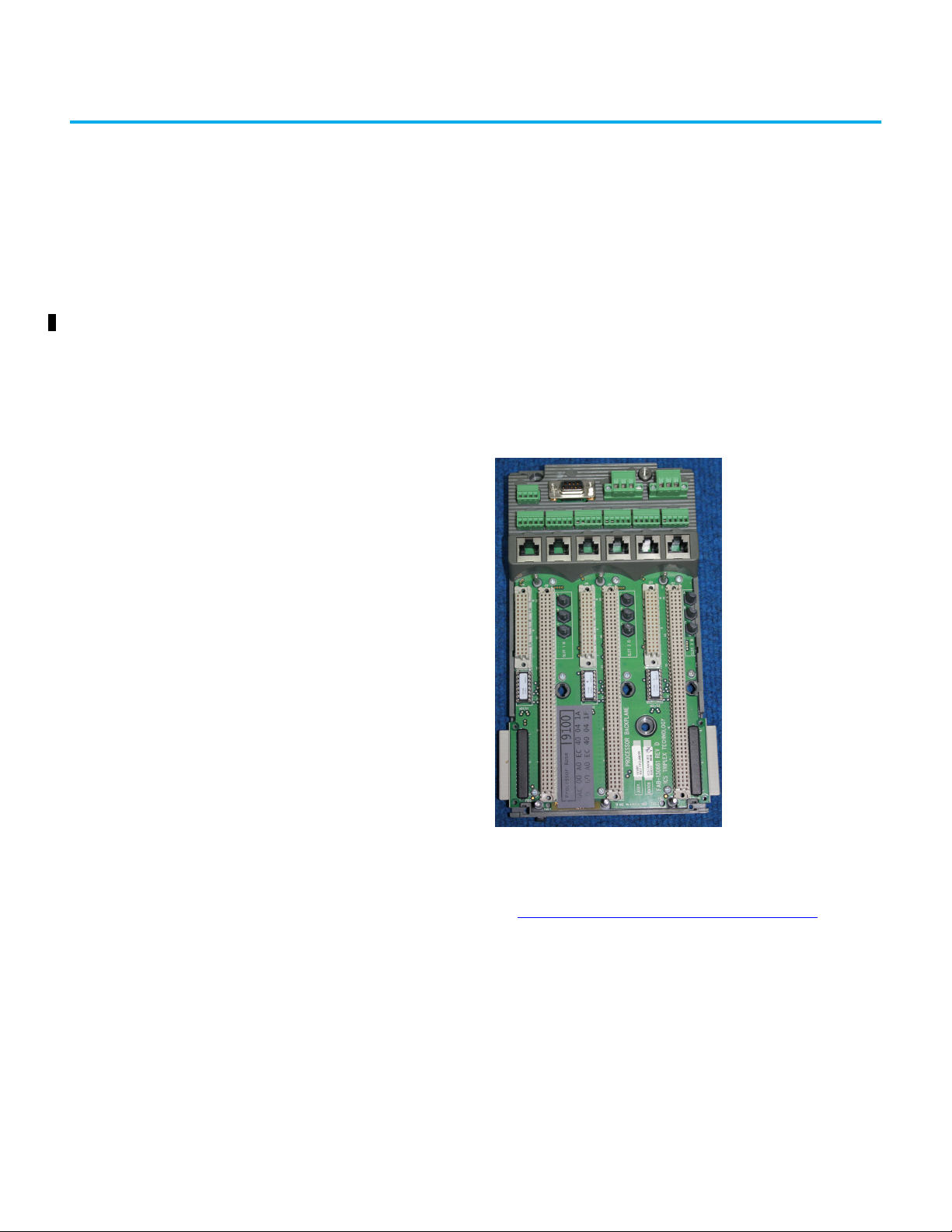
AADvance Processor Modules are mounted on a Processor Base Unit. Up to
three Processor Modules can be mounted on the Processor Base Unit as shown
below:
The Processor Base Unit connects to Input/Output (I/O) Base Units to form an
interlocking backplane. The combined Processor and I/O Module assemblies
comprise the Controller. The interlocked backplane is latched securely against
a metal DIN rail. See also, Configuring the Controller I/O
Processor Modules can be mounted in any order onto any of the slots on the
Processor Base Unit. However, for the controller to communicate with
Workbench, the correct Internet Protocol (IP) address of the occupied position
on the Processor Base Unit must be selected. For explanation, see below.
on page 109 .
Controller IP Address The AADvance controller stores its IP address data in non-volatile memory in
the 9100 processor base unit. The data is independent of the 9110 processor
modules in the controller, and so the controller keeps the address information
when you remove a processor module.
Rockwell Automation Publication ICSTT-RM458D-EN-P - February 2021 25
Page 26
Chapter 3 Connecting the AADvance Workbench to the Controller
You must set up the IP address data when you create a new system, or if you fit
a new processor base unit.
After having set up the IP address data in the controller, you can configure the
AADvance Workbench to find the controller on the network.
Allocating IP Addresses for Network Communications
For some systems, the administrator of the local area network will allocate the
IP address for the controller. If this has not occurred, use an address from the
ranges allocated to private networks:
• 10.0.0.0 to 10.255.255.255 (10/8 prefix)
• 172.16.0.0 to 172.31.255.255 (172.16/12 prefix)
• 192.168.0.0 to 192.168.255.255 (192.168/16 prefix).
Each controller on a local area network must have a unique IP address.
IMPORTANT
Make sure that the two Ethernet ports on each 9110 processor
module are on different subnets.
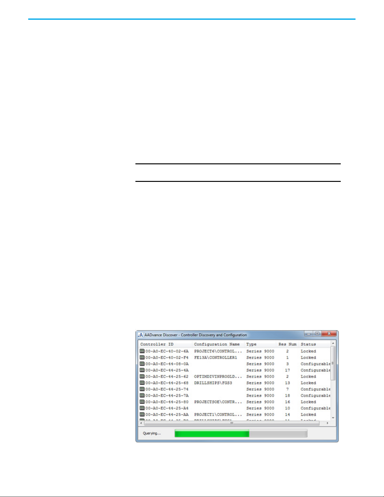
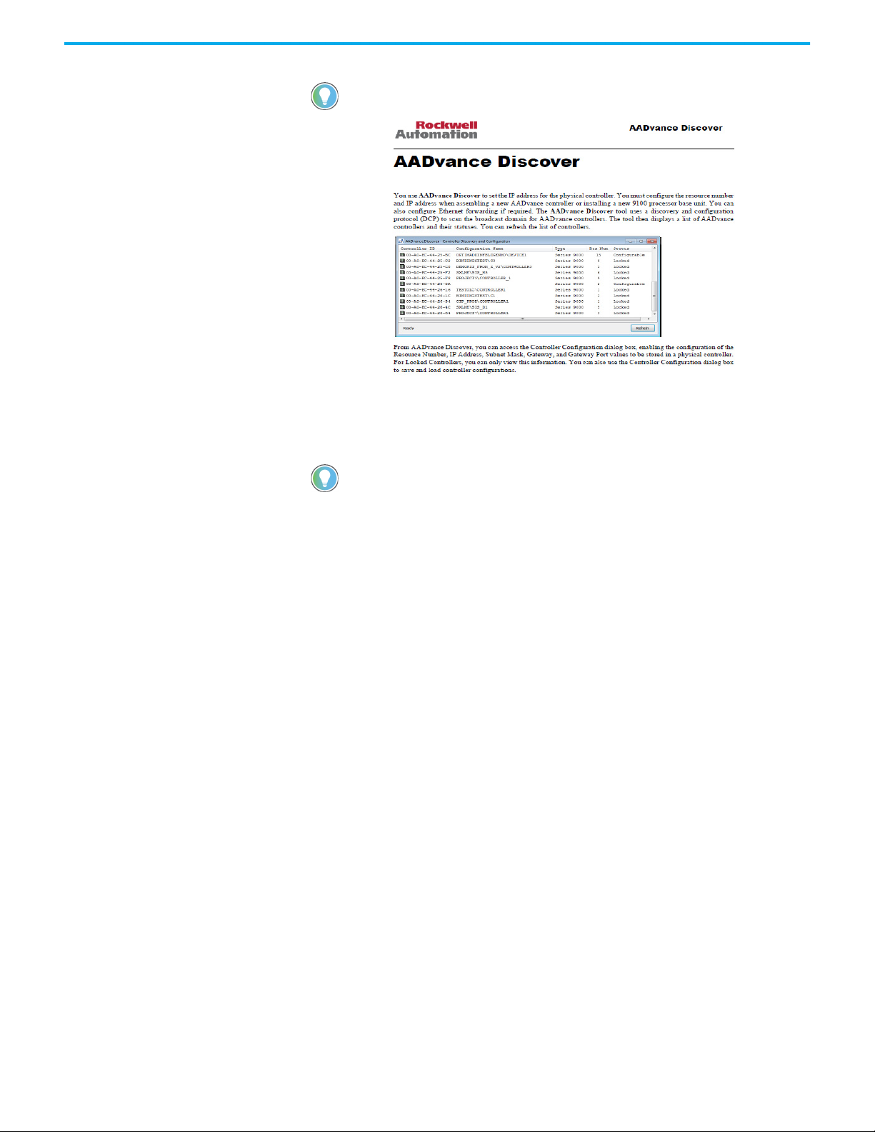
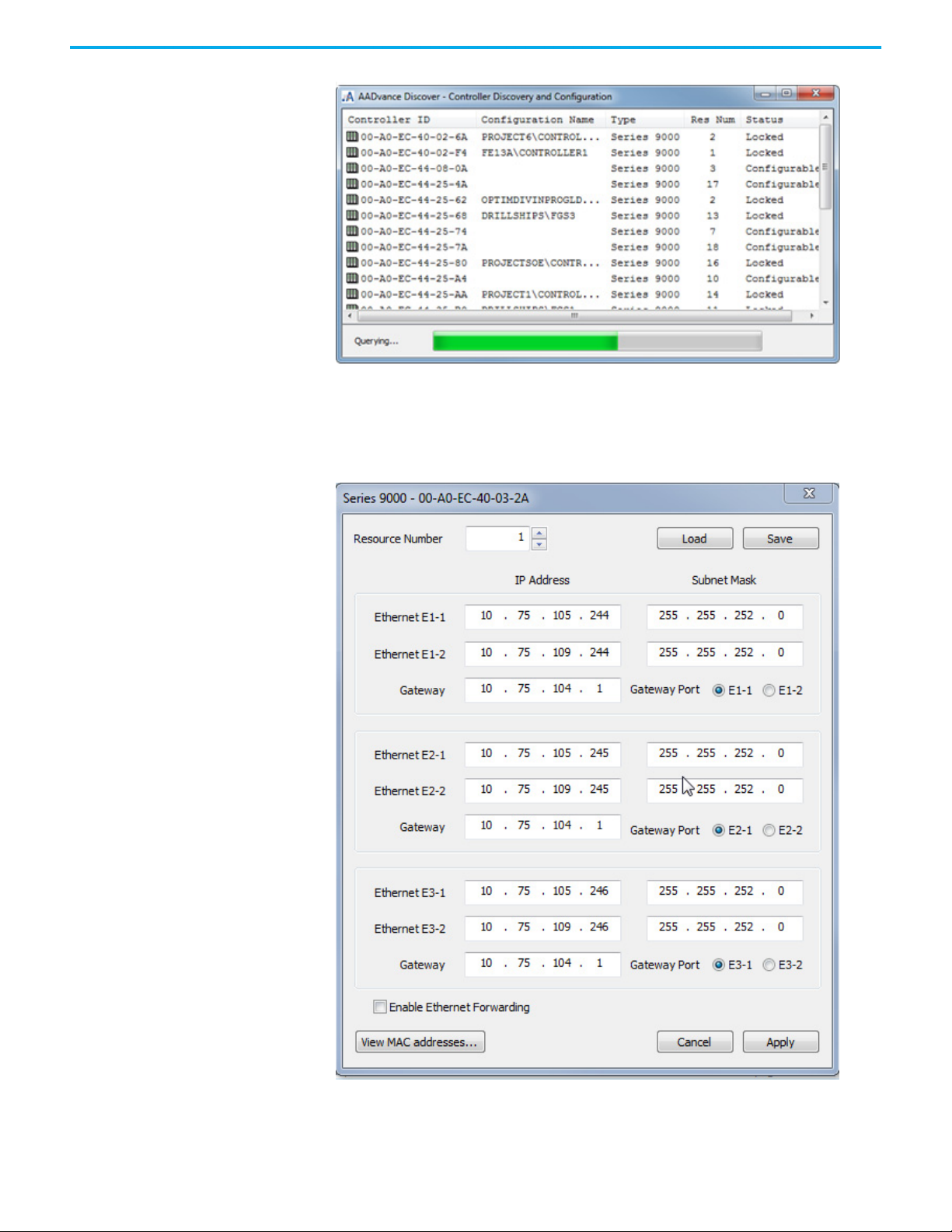
AADvance Discover Utility You use the AADvance Discover utility to set up the controller IP address. The
utility uses a discovery and configuration protocol (DCP) to perform a scan of
the broadcast domain for AADvance controllers and enables you to configure
the resource number and IP Address to be stored in a controller. You can use
the utility to save configurations and load them again in the future.
The AADvance Discover utility is part of the AADvance Workbench
installation. It appears on the drop-down list in the View menu, which is a tab
on the main menu bar.
There is also a feature on the Windows Start menu:
Click “Windows Start” “All Programs”. “Rockwell Automation”
“AADvance 2.1” “AADvDiscover” to start the utility.
The utility displays a list of the AADvance controllers on the broadcast
network, and reports a status for each one.
26 Rockwell Automation Publication ICSTT-RM458D-EN-P - February 2021
Page 27
Chapter 3 Connecting the AADvance Workbench to the Controller
If the The AADvance discover utility is selected and the [F1] key is pressed on
the keyboard a .pdf help-file is opened.
Double-clicking on an entry in the list enables examining the resource and IP
address settings for a controller. A Refresh button enables a scan of the
network and creates a new list.
If a controller known to be on the network does not show in the list, look for
communication blocking or miss-routing by Windows or by other network
devices. DCP communications will not go through network bridges and
routers.
The DCP is proprietary to Rockwell Automation. It uses the first MAC address
of the 9100 processor base unit to identify each individual controller - the MAC
address is the 'Controller ID' in the list.
The controller status will be 'No Response', 'Locked' or 'Configurable':
• 'No response' means that the controller is turned off, or the
communications between the computer running the utility and the
controller have failed.
• 'Locked' means that the utility has established communications with the
controller, but one or more of the criteria for 'Configurable' status is not
present.
• 'Configurable' means that the controller can be configured with its IP
address. The utility has established communications with the controller,
the program enable key is present (this plugs into the KEY connector on
the 9100 processor base unit) and either no application is loaded or an
application is loaded but not running.
The status must be shown as 'Configurable' before you can set the controller
configuration. If you change the configuration of a controller, click the
Refresh button to make a new list.
A status bar is displayed at the bottom of the window, below the list. This will
show the message 'Initializing' as the tool starts followed by 'Searching',
locating all the controllers connected to the network, then 'Querying' and
finally 'Ready':
• 'Querying' scans the network for controllers and creates a list
• 'Ready' means the controller status and IP addresses are displayed ready
for new settings.
Rockwell Automation Publication ICSTT-RM458D-EN-P - February 2021 27
Page 28
Chapter 3 Connecting the AADvance Workbench to the Controller
A Refresh button allows you to repeat the Querying process.
Configure the IP Address in the Controller
When you assemble a new AADvance controller, or install a new 9100
processor base unit, you have to configure the IP Address stored in the
controller.
The procedure to configure the IP Address uses the AADvance Discover utility.
Changes occur immediately and you do not have to start the controller again.
To set the IP Address do the following:
1. Write down the controller's first MAC address (the Controller ID)
displayed on a label on the processor base unit. Install at least one 9110
processor module into the processor base unit.
2. Make sure the program enable key is inserted in the KEY connector on
the processor base unit.
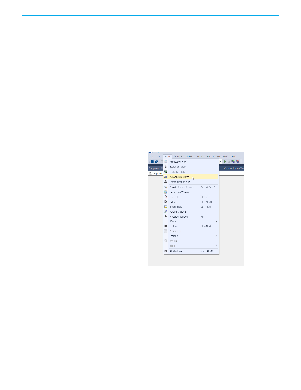
3. The AADvance Discover utility may be opened, either from the view tab
on the menu bar, or through the Windows Start menu.
• To start the AADvance Discover tool from the view tab on the menu bar
within Workbench 2.1:
Click View AADvance Discover as shown below.
The AADvance Discover utility scans the network for controllers, and creates a
list.
28 Rockwell Automation Publication ICSTT-RM458D-EN-P - February 2021
Page 29
Chapter 3 Connecting the AADvance Workbench to the Controller
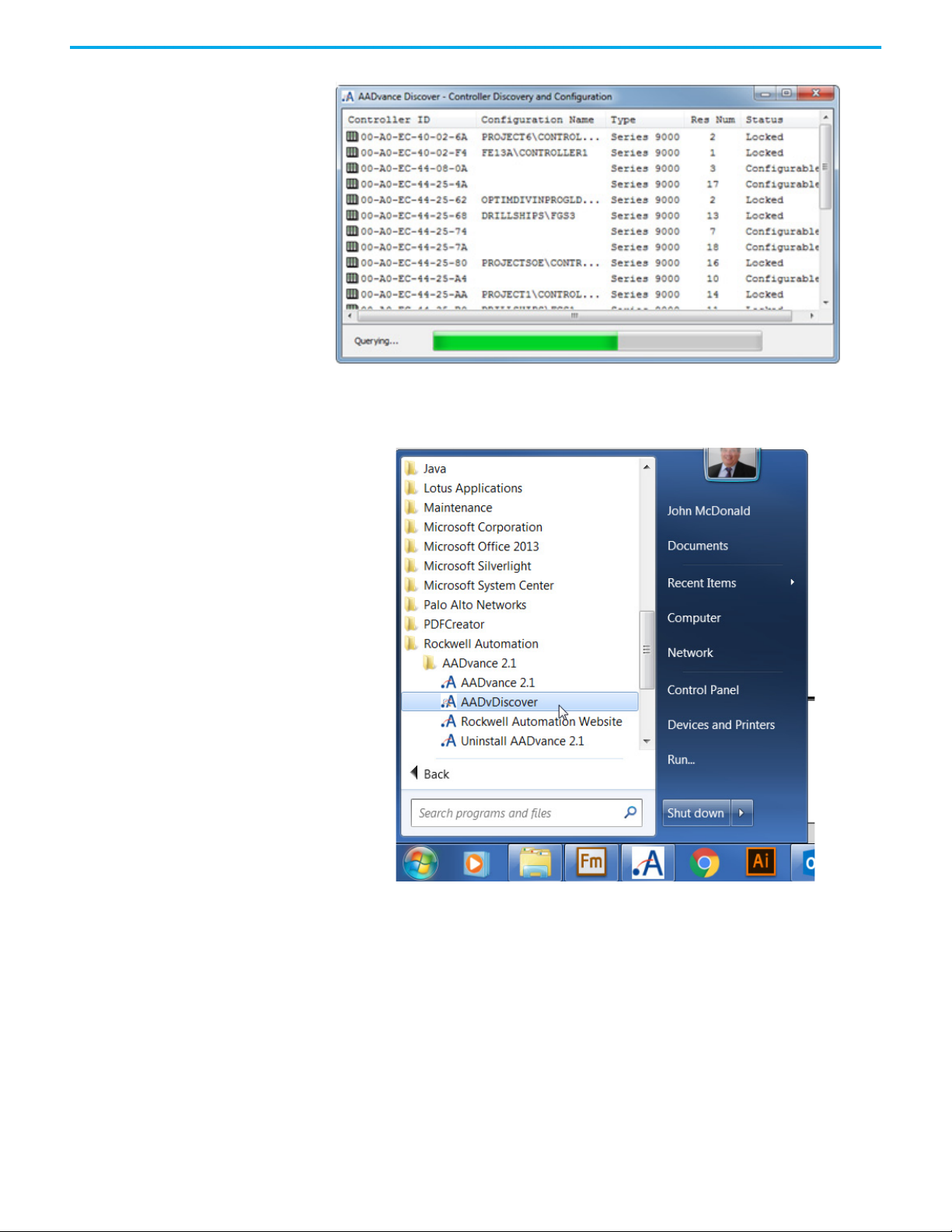
• Alternatively start the AADvance Discover tool from the Windows
Start menu:
Start All Programs Rockwell Automation AADvance 2.1
AADvDiscover as shown below.
The AADvance Discover tool above scans the network for controllers, and
creates a list.
Rockwell Automation Publication ICSTT-RM458D-EN-P - February 2021 29
Page 30
Chapter 3 Connecting the AADvance Workbench to the Controller
4. Locate the controller in the list and make sure that the status of the
controller is Configurable.
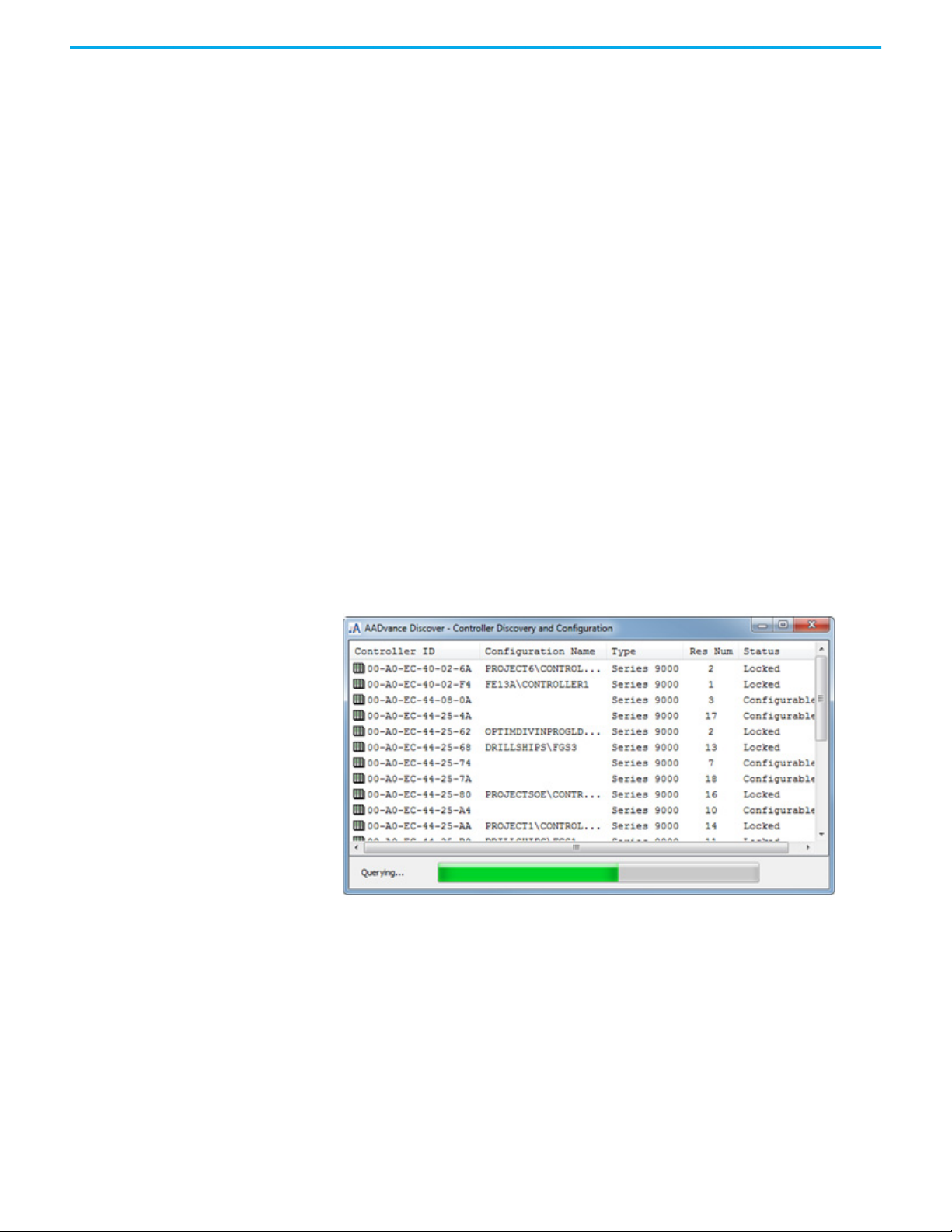
5. Double-click on the MAC address in the Controller ID field.
• The Resource Number, IP Address and Subnet Mask dialog boxes are
displayed.
6. Enter the IP Address and Subnet Mask into the fields for each Ethernet
port.
7. Enter the Gateway values for each processor module, then click Apply.
30 Rockwell Automation Publication ICSTT-RM458D-EN-P - February 2021
Page 31
Chapter 3 Connecting the AADvance Workbench to the Controller
• Returning to the main window of the utility, the controller status will
show In Progress and then Configurable.
• The controller uses the new settings.
Configure the Controller Resource Number in the Controller
When assembling a new AADvance controller or installing a new 9100
processor base unit, the resource number stored in the controller must be
configured. The resource number is a type of device address, and it must also
be configured in the application.
The procedure to configure the resource number uses the AADvance Discover
utility. To set the resource number do the following:
1. Write down the controller's first MAC address (the Controller ID)
displayed on a label on the processor base unit. Install at least one 9110
processor module into the processor base unit.
2. Make sure the program enable key is inserted in the KEY connector on
the processor base unit.
3. Start the AADvance Discover tool:
a. Either from the view tab on the main menu bar within Workbench 2.1:
•Click View AADvance Discover
b. Or from the Start menu:
•Start All ProgramsRockwell Automation AADvance2.1
AADvDiscover.
The AADvance Discover utility scans the network for controllers and
creates a list.
4. Locate the controller in the list and make sure that the status of the
controller is Configurable.
5. Double-click the MAC address in the Controller ID field.
• The Resource Number, IP Address and Subnet Mask dialog boxes are
displayed.
Rockwell Automation Publication ICSTT-RM458D-EN-P - February 2021 31
Page 32

Chapter 3 Connecting the AADvance Workbench to the Controller
6. Enter the resource value into the Resource Number field, then click
Apply.
• Returning to the main window of the utility, the controller status will
show Pending Restart.
7. To finish the update, turn off the power to the controller.
8. Start the controller. Refresh the screen to make sure that the new
resource number is shown in the resource field and that the controller
status is configurable.
IMPORTANT
The unique number identifying a resource within a project must
also be configured in the Properties/Properties Window for the
specified controller. See Configure Controller Properties on
page 58
This can be seen, in the following screen-shot, as legend “Number” in the Properties box for “Device Controller1” in Application View.
32 Rockwell Automation Publication ICSTT-RM458D-EN-P - February 2021
Page 33

Chapter 3 Connecting the AADvance Workbench to the Controller
Configure the IP Address of the Target Controller
To connect the AADvance Workbench project to the target controller you have
to indicate the IP addresses allocated for the controller to the project.
1. Select the Communication View.
2. Double-click the Ethernet node. The Ethernet Ports table screen is
displayed.
3. Enter the IP Address for each port
• Where a port has been left "Not Configured" the port can be
configured individually.
4. Select the "Not Configured" port.
5. Enter the IP Address for the port.
Rockwell Automation Publication ICSTT-RM458D-EN-P - February 2021 33
Page 34

Chapter 3 Connecting the AADvance Workbench to the Controller
System Security An AADvance system, with its workstations and DCS interfaces, whether using
Ethernet networks or Serial links is likely part of a larger corporate network
which may expose the system to accidental or malicious infection, attack or
less obvious security vulnerabilities. If appropriate (or defined in the SRS), a
security risk assessment should be carried out and the appropriate level of risk
mitigation applied.
The following general security steps should be used to verify that the system is
secure:
WARNING: Network and workstation security must be set up when
installing and setting up the system. As a minimum use the following
security measures:
• The AADvance system must not be connected to a network with open
unsecured access to the Internet.
• A router firewall must be active on the Workstation, helping prevent
access to the unused Ethernet ports on each communication interface.
• Anti-virus software must be installed and be kept updated.
IMPORTANT
• If the workstation is a laptop, it must be kept locked when not in use.
• The Workbench software must be password protected. This can be done
when the Workbench is installed.
• The application must be password protected if a program enable key is
not used on the system.
Firewalls have been known to affect the operation of the
AADvance Discover utility so it may be necessary to
temporarily disable the Firewall when using this tool.
Workbench Access
Passwords are used to protect Project access and target AADvance Controller
access.
34 Rockwell Automation Publication ICSTT-RM458D-EN-P - February 2021
Page 35

Chapter 3 Connecting the AADvance Workbench to the Controller
Setting Project Access Control
For project security, access control may be set using a password for projects,
controllers, programs, libraries, and library functions and function blocks.
Password definitions are limited to eight characters and can consist of letters,
digits, and symbols. When projects are password-protected they cannot be
opened for editing. Project sub-elements, can have their own level of access
control. For example, a program having its own password remains locked and
cannot be modified without entering its password.
NOTE Because programs are encrypted, password definitions must be
retained.
In Application View, the following indicates the security state for elements:
The closed padlock indicates that a lock is applied to the element.
When opening a project having password-protected elements, the prompt to
enter the password is only offered once for each element. Password-protected
elements have the following modification restrictions:
Password-Protected Element Modification Restrictions
Project Opening the project
Controller
Program Viewing the program
Library Adding, editing and deleting a library function or function block
Library Function Viewing the function
Library Function Block Viewing the function block
Adding, editing and deleting a program, modifying the communication
protocols, modifying the system type and controller properties, wiring
variables and adding, editing and deleting input / output modules
Existing passwords may be edited for projects and project sub-elements.
Existing passwords may also be removed. When copying, pasting, importing
and exporting elements which have access control, password definitions are
retained.
Rockwell Automation Publication ICSTT-RM458D-EN-P - February 2021 35
Page 36

Chapter 3 Connecting the AADvance Workbench to the Controller
To set a password
1. In the Application View, right-click the controller instance, and then click
Set Password.
2. In the Set Password dialog box, enter the required information, then
click OK.
• In the New Password field, type the required password.
• In the Confirm Password field, re-type the required password.
To edit a password
1. In the Application View, right-click the required element, and then click
Set Password.
2. In the Change Password dialog box, enter the required information, then
click OK.
• In the Old Password field, type the current password.
• In the New Password field, type the required password.
• In the Confirm Password field, re-type the required password.
To remove a password
1. In the Application View, right-click the required element, and then click
Set Password.
2. In the Change Password dialog box, enter the required information, then
click OK.
• In the Old Password field, type the current password.
• The New Password and Confirm Password fields must remain blank.
The element is no longer password-protected.
36 Rockwell Automation Publication ICSTT-RM458D-EN-P - February 2021
Page 37

Chapter 3 Connecting the AADvance Workbench to the Controller
Setting Target Access Control
For controller security, access control may be set by defining a password for
the target AADvance controller. Password definitions are limited to eight
characters and can consist of letters, digits, and symbols. The target password
protects the following operations:
• stopping the application
• downloading the application
• updating the application
•locking variables
• modifying the value of a variable.
Existing passwords may be edited for targets. Existing passwords can also be
removed for target controllers. When setting, editing, and deleting the
password for a controller target, the attached target must be running.
To set a password for a target
1. In the Application View, right-click the controller instance, and then click
Set Target Password.
2. In the Set Password dialog box, enter the required information, then
click OK.
• In the New Password field, type the required password.
• In the Confirm Password field, re-type the required password.
To edit a password for a target
1. In the Application View, right-click the required controller, and then
click Set Target Password.
2. In the Set Password dialog box, enter the required information, then
click OK.
• In the Old Password field, type the current password.
• In the New Password field, type the required password.
• In the Confirm Password field, re-type the required password.
Rockwell Automation Publication ICSTT-RM458D-EN-P - February 2021 37
Page 38

Chapter 3 Connecting the AADvance Workbench to the Controller
To remove a password for a target
1. In the Application View, right-click the required controller, and then
click Set Target Password.
2. In the Set Password dialog box, enter the required information, then
click OK.
• In the Old Password field, type the current password.
• The New Password and Confirm Password fields must remain blank.
The target is no longer password-protected.
Threat Analysis
A system threat analysis must be performed and all high risk threats mitigated
before the system is commissioned.
Integrating the AADvance Controller with Other Systems
The AADvance controller connects to existing control systems and plant
monitoring equipment. This connection enables a third-party control system
read the state of sensors connected to the controller.
The connection interfaces are through the controller network ports and serial
ports, and use the following protocols:
• CIP over EtherNet/IP
•Modbus RTU
• Open Modbus/TCP
• OLE for Process Control (OPC).
IMPORTANT
It is strongly advised that network firewalls and Windows
operating system firewalls are activated in order to support the
integrity of the AADvance system.
Network Firewall If the network used by the AADvance system is connected to another network,
the connections should pass through a firewall.
The following transport layer ports (services) are supported by AADvance;
some ports are always open, others are only open when configured.
AADvance Communication Ports
Protocol Port Number Port Open Purpose Port Open When
TCP 502 When configured Modbus TCP slave
TCP 1132 Always
TCP 2000 When configured Modbus RTU slave
38 Rockwell Automation Publication ICSTT-RM458D-EN-P - February 2021
ISaGRAF®, application
downloads, debug, SoE etc.
Open if Controller is
configured as a Modbus TCP
slave.
N/A
Open if controller is
configured as a Modbus RTU
slave.
The default port, 2000, is
given in this table.
Page 39

Chapter 3 Connecting the AADvance Workbench to the Controller
Protocol Port Number Port Open Purpose Port Open When
Serial tunneling must be
TCP 10001- 10006 When configured
TCP 44818 Always CIP Produce & Consume N/A
TCP 55555 Always
UDP 123 When configured (S)NTP
UDP 1123,1124 When configured IXL bindings
UDP 2010 Always
UDP 2222 When configured CIP Produce & Consume I/O
UDP 5000 When configured Trusted® peer-to-peer (P2P)
UDP 44818 Always CIP Producer & Consume N/A
(1) The Telnet service provides various commands to gather diagnostic information about the controller and interact
with it. It is intended to be used by Rockwell Automation Support Engineers, or users acting under the guidance of
Rockwell Automation Support Engineers. It is important that this service should only be available to authorised
users whose access is limited to the control network. The service must not be made available over the corporate
network or the internet. When not required, the service should be blocked, even within the control network.
Additionally, the programme enable key should be removed from the controller in normal use.
Transparent Comms
Interface (Serial Tunneling)
Telnet (diagnostic interface)
(1)
Discovery and configuration
protocol (DCP, Rockwell
Automation)
enabled AND the resource is
not currently loaded.
The ports will be closed
when the resource is
restarted.
N/A
The controller is configured
as either a SNTP client or
server.
The ports are otherwise
closed.
Application uses IXL
bindings
• 1123 open on a producer
• 1124 open on a consumer
N/A
Open if CIP Produce &
Consume I/O traffic is active
At least one P2P network /
subnet has been configured
and is enabled.
Those ports that are always open, even when not configured or unused, are
open to unauthorized access. Use the following guidelines to protect all open
transport layer ports.
1. If the network used by the AADvance system is connected to another
network, the connection should pass through a firewall, to protect the
AADvance system from potential threats from the other networks.
Techniques to protect a control network from the rest of the plant’s
network are described in the RA/Cisco CPwE Design and
Implementation Guide (ENET-TD001-EN-P). See below for some advice
from the CPwE.
2. The firewall should be configured to block all communication ports. If
necessary a specific port may be enabled to a device that needs to
communicate with other devices on other networks.
3. Ingress rate limiting should be used to protect the AADvance from
network storms. The limit chosen should not impede the expected peak
ingress rate for that controller and should be determined by calculation
or observation of the system's network traffic when running.
4. The SNCP port must only be allowed to pass through the firewall if the
Windows PCs running the AADvance Workbench are on a separate
network.
5. The variable bindings ports must only be allowed to pass through the
firewall if the AADvance controller is communicating with another
AADvance controller on a separate network.
6. The other communication ports (e.g. MODBUS, SNTP) must only be
allowed to pass through the firewall if the AADvance controller or
Windows PC communicates with other devices on other networks.
Rockwell Automation Publication ICSTT-RM458D-EN-P - February 2021 39
Page 40

Chapter 3 Connecting the AADvance Workbench to the Controller
From the CPwE advice, techniques for securing a control network include (but
are not limited to):
• Physical access to the Cell/Area zone should be restricted to authorized
users. Especially, physical access within the Cell/Area zone to AADvance
systems should be tightly controlled.
• Switches within the Cell/Area zone should be configured to permit only
authorized devices (eg by MAC address).
• A firewall should be used to help prevent access to ports at the boundary
to the Cell/Area zone.
• When it is known that services are not required to a device within the
Cell/Area zone, then for enhanced security, firewall devices can be
employed in “transparent mode” to protect the AADvance controllers,
blocking access to the ports requiring protection.
Windows PC Firewall The firewall on the Windows PC should be active. It should be configured to
allow connections through the ports used to communicate with the AADvance
Controller. Other ports may be configured for other applications (e.g. HMI,
time synchronization, access to file shares on servers, Windows Update, virus
detection software).
Save and Load a Configuration
It may be necessary to allow the Windows PCs to access Windows Updates,
time synchronization and virus updates.
Windows PCs may also run other software (e.g. HMI, data logging), for which
it may be necessary to allow other ports to pass through the firewall. Refer to
the manufacturer’s manual for details.
NOTE It is beyond the scope of this document to detail how to configure
a firewall. Refer to the manufacturer’s manual for instructions
about firewall settings. It is recommended that the firewall
settings are backed up in case of a firewall hardware failure.
Save a Configuration File
After having entered the IP Address details you can now save the
configuration:
40 Rockwell Automation Publication ICSTT-RM458D-EN-P - February 2021
Page 41

Chapter 3 Connecting the AADvance Workbench to the Controller
1. Click Save after having entered your required configuration.
2. Assign a name to the configuration and save it to an applicable location.
Rockwell Automation Publication ICSTT-RM458D-EN-P - February 2021 41
Page 42

Chapter 3 Connecting the AADvance Workbench to the Controller
Reload a saved Configuration File.
To reload a saved configuration file:
1. Open the AADvance Discover utility.
2. Double click a MAC address to open the Configuration dialog box.
3. Click Load to load the saved configuration.
4. Select the Configuration file where it was saved.
5. Confirm that the configuration loaded is the same as the saved
configuration.
Replace an Application To replace an application you have a choice of two methods. Method one uses
the Clear and Download commands of the Project menu. Method two is a
manual procedure that requires you to remove the processor modules.
Project Clear Command Procedure
1. Build a new project using the same IP address as the current project.
2. Connect to the system that has the project you want to replace.
3. Select Clear command from the Project drop-down menu.
42 Rockwell Automation Publication ICSTT-RM458D-EN-P - February 2021
Page 43
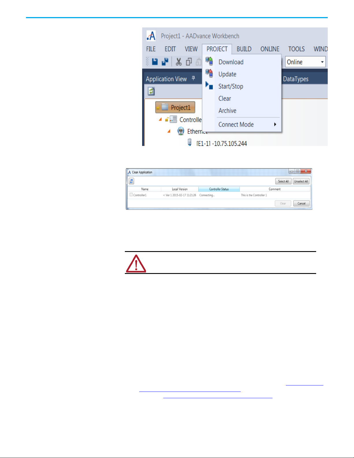
Chapter 3 Connecting the AADvance Workbench to the Controller
• A Clear Application window appears.
4. Choose the controller (s).
• The application will be cleared from that controller.
5. Use the Download option to download the new project to the controller.
Manual Procedure
WA RN I NG : Ensure you take alternative measures to protect your business
application before stopping an application in a Safety System.
1. Power down the system.
2. Remove all the processor modules.
3. Insert a processor into the previously empty slot on the T9100 base unit.
4. Power up the system and let the processor start for one minute until the
Ready LED is green but the Run LED is red.
• The processor will detect that its application does not match the
signature on the base unit and will delete all its application files.
5. Power down the system.
6. Remove the cleared processor module.
7. Insert the cleared processor module in the slot where you connect the
Ethernet port, usually the left slot (Slot A).
8. Power up the system and let the processor start for one minute until the
Ready LED is green but the Run LED is red
9. Use AADvance Discover to configure the IP address (See Configure the
IP Address in the Controller on page 28) and save the configuration
(Refer to Save and Load a Configuration
on page 40).
10. Press the Apply Tab, located in the bottom right corner of the
Configuration Dialog Box, to apply the configuration file.
11. Download the application from Workbench.
Rockwell Automation Publication ICSTT-RM458D-EN-P - February 2021 43
Page 44

Chapter 3 Connecting the AADvance Workbench to the Controller
12. Wait until the application has downloaded and the Ready and Run LEDs
go green.
13. Insert a 2nd processor of a dual configuration and let it educate from the
other processor.
14. Once the 2
it active.
15. Repeat if a third processor is required.
nd
processor’s Run LED is amber, press its Reset button to set
44 Rockwell Automation Publication ICSTT-RM458D-EN-P - February 2021
Page 45

Chapter 4
Starting a Project and Defining the Controller
The configuration process starts by making a new AADvance® project or
importing an existing project. After you have a project, you can use the
Equipment View and the Communication View to move around the project,
configure the controller type and, if applicable, add more controllers. You can
then configure the timing, communications and hardware for the controllers.
IMPORTANT
When first adding a project the Controller nodes are called
Controller 1, 2, etc. For the purpose of the screen captures for
this manual, the names of the Controller nodes have been
changed to Config1, 2, etc. You can change the controller node
names as required.
Reset Window Layout The Workbench desktop screen is highly customizable and can be changed to
suit user preference. The changes are automatically saved when the
Workbench is shut-down and the new display settings are used the next time
the Workbench is opened. However, if at any time the user wishes to return to
the default screen environment, this can readily be achieved by using either
the Window tab or Tools tab from the main menu.
If the Window tab is selected, a drop-down box opens to reveal Reset Window
Layout as one of the options.
Selecting the Reset Window Layout option opens a dialog box to confirm the
user choice.
Rockwell Automation Publication ICSTT-RM458D-EN-P - February 2021 45
Page 46

Chapter 4 Starting a Project and Defining the Controller
Selecting the Yes button restores the original default setting as illustrated in
the Quick Start Guide
For other screen selection options, selecting the Tools tab opens a drop-down box. The drop-down menu includes Import and Export Settings.
Selection of Import and Export Settings, opens the Import and Export
Settings Wizard, which also has an option to restore the screen environment
to one of the default collections of settings.
on page 13 .
Help The AADvance Workbench includes a comprehensive Help section, which is
accessed by selecting the Help tab on the main menu.
46 Rockwell Automation Publication ICSTT-RM458D-EN-P - February 2021
Page 47

Chapter 4 Starting a Project and Defining the Controller
Selecting the View Help command opens the help viewer,
which displays the Help Contents and the Help Viewer Home page.
Make a New Project 1. Start the software if it is not already running by clicking Start All
Programs
click on the AADvance 2.1 icon located on desktop.
2. Select File then New Project (or press <ctrl> + <shift> + N). The New
Project dialog box is displayed.
Rockwell Automation AADvance 2.1 AADvance 2.1 or
Rockwell Automation Publication ICSTT-RM458D-EN-P - February 2021 47
Page 48

Chapter 4 Starting a Project and Defining the Controller
3. In the Project Types field select Series 9000.
4. Enter a project name, in this case Rockwell_ Training_Project_1 and add
a comment in the comment field.
Make sure that the project name begins with a letter or an underscore (_),
followed by letters, digits, and single underscores and also follows the
rules for a Windows file name. Do not use space characters in the project
name.
5. Click OK. The AADvance Workbench creates a project. The project is now
created.
6. Steps 7
through to 12 are included to show how the screen appearance
may vary, depending on the selected view. For step 13 to work it doesn’t
matter which view is selected.
7. Select project node (Application view).
48 Rockwell Automation Publication ICSTT-RM458D-EN-P - February 2021
Page 49

Chapter 4 Starting a Project and Defining the Controller
8. Select controller node (Application view).
9. Select Equipment view.
10. Select project node (Equipment view).
Rockwell Automation Publication ICSTT-RM458D-EN-P - February 2021 49
Page 50

Chapter 4 Starting a Project and Defining the Controller
11. Select controller node (Equipment view).
It can also be seen that the large window has an Equipment tab on the
left side along the top. Also the equipment node, followed by the project
node are seen below the Equipment tab.
The Controller node is now also seen after the project node.
12. Re-selection of Application view does not change the appearance of the
large window.
50 Rockwell Automation Publication ICSTT-RM458D-EN-P - February 2021
Page 51

Chapter 4 Starting a Project and Defining the Controller
13. Select the required system tree node (project or controller). Initially
project node is chosen.
14. Select Properties Window from the VIEW tab.
15. Select Description in the properties window.
16. Left-click on the button on the right hand side of the next column of the
description row.
Rockwell Automation Publication ICSTT-RM458D-EN-P - February 2021 51
Page 52

Chapter 4 Starting a Project and Defining the Controller
17. The project name appears before “- Description” on the description
window.
18. Add a description to the description window.
Import Existing Project Procedure to import an existing project
To import an existing project, do the following:
1. Launch the software if it is not already running by clicking:
52 Rockwell Automation Publication ICSTT-RM458D-EN-P - February 2021
Page 53

Chapter 4 Starting a Project and Defining the Controller
Start All Programs Rockwell Automation AADvance 2.1
AADvance 2.1 or Click on the AADvance 2.1 icon located on desktop.
2. Select File, then New Project (or press <ctrl> + <shift> + N).
3. The New Project dialog box is displayed.
4. In the Project Types field, select Import.
5. From the Templates list, select Import AADvance Project.
6. Enter a project name (add a comment, if required).
• The project name must begin with a letter or an underscore (_)
followed by letters, digits, and single underscores, and must also
follows the rules for a Windows file name. Do not use "spaces" in the
name
7. Left-click Browse to select the database path.
8. In the Select Database File dialog box, locate and select the project
database file (*.mdb), and then click Open
NOTE You may encounter a message asking if you want to update the
database to the current version.
After updating the database, the project can no longer be opened
in a previous version of the Workbench.
To continue the importation process, click OK.
9. In the New Project dialog box, click the OK button
Rockwell Automation Publication ICSTT-RM458D-EN-P - February 2021 53
Page 54

Chapter 4 Starting a Project and Defining the Controller
If required, select the project node, then Description Window, from the
drop-down box for the VIEW tab.
Procedure for Opening An Existing Project
Then add a description in the in the description window.
If CIP is configured in the project, select the Ethernet ports for the CIP binding
groups.
Compile the project and download it to each controller.
To open a project from the Workbench.
1. From the File menu, click Open Project (or press Ctrl+Shift+O).
2. In the Open Project dialog box, select the required project, and then click
OK.
The project structure is displayed in the Application View.
To open a project from the Projects directory
From the Windows Explorer, access the Projects directory and perform one of
the following:
• Double-click the required *.aadsln file.
• Drag the *.aadproj or *.aadsln file onto the desktop Workbench icon.
The Workbench opens displaying the required project.
Equipment View The Equipment view displays a graphical view of the project hardware in a
logically organized tree. The tree has a configuration for each AADvance
controller and each Eurocard controller defined in a project has a single IO Bus
(IO Bus 1) with 18 slots available.
54 Rockwell Automation Publication ICSTT-RM458D-EN-P - February 2021
Page 55

Chapter 4 Starting a Project and Defining the Controller
Each standard or mixed controller defined in a project has two IO Buses (IO
Bus 1 and IO Bus 2) with 24 slots available for each IO Bus.
The bus has a series of slots for I/O modules and the tree shows the modules in
their correct slots.
Rockwell Automation Publication ICSTT-RM458D-EN-P - February 2021 55
Page 56

Chapter 4 Starting a Project and Defining the Controller
The Equipment view enables performing multiple actions, such as the
following:
• configure the system type for a controller
• add or edit a controller
• add or edit I/O modules
• move or copy modules in a controller configuration
• copy modules from one controller to another
• configure the process safety time
• wire application variables to I/O channels
• define input thresholds (analogue and digital inputs)
• configure the behavior of output channels
• configure HART communications
• wire application variables to processor variables
• configure and use the real-time clock.
The context menus for the different nodes in the tree contain the actions
relevant to the node.
Communication View The Communication view is a graphical environment that displays
information about communication set up and events. The Communication
View displays a tree-like structure showing the available external
communication functions and configuration.
In the Communication view you select the system tree nodes to access
communication options for the system. In this view you can select specific
communication functionality such as Serial Ports or Modbus and configure
them for your system.
56 Rockwell Automation Publication ICSTT-RM458D-EN-P - February 2021
Page 57

Chapter 4 Starting a Project and Defining the Controller
Application View The Application view is an interface that displays a graphical view of projects
in a logically organized tree structure. Projects include controllers, programs,
functions, function blocks, controller variables, data types and libraries. A
project can include multiple controllers. The physical locations of a project file
can differ from the representation in the tree view structure. You can perform
the project set up and configuration tasks using the contextual menus.
Add a New Controller To add a new controller to a project:
1. Select the project in the Application view, Communication view or
Equipment view.
Rockwell Automation Publication ICSTT-RM458D-EN-P - February 2021 57
Page 58
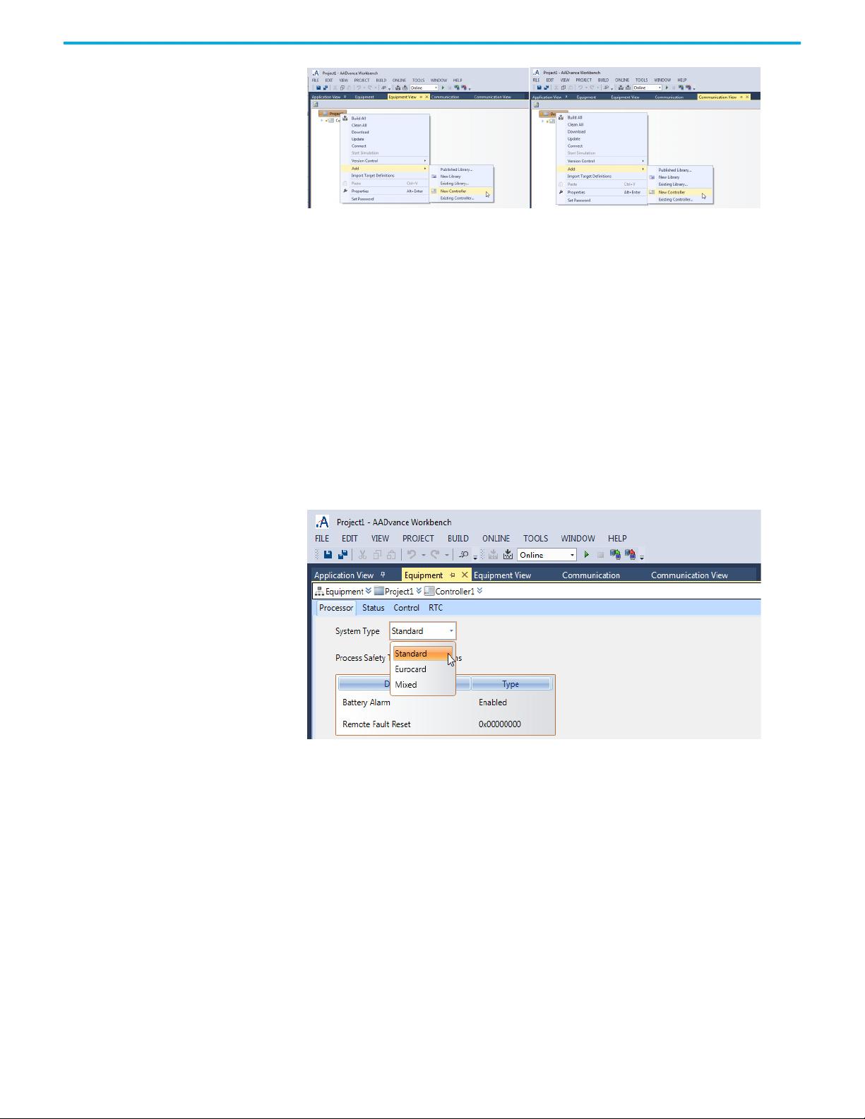
Chapter 4 Starting a Project and Defining the Controller
2. Open the contextual menu, select Add > New Controller.
3. Give a meaningful name to the controller. Select the controller in the tree
4. Type in the name for the controller, press Enter.
• the AADvance Workbench creates a controller node in the tree.
• the new controller node has a standard name.
view and open the contextual menu, then select Rename.
Configure the Controller Type
The AADvance Workbench supports three types of AADvance controller: the
standard product, the Eurocard controller and a mixed controller. The 'mixed'
controller type lets you configure a standard controller with standard I/O and
Eurocard I/O in the two 24-slot I/O buses.
You must set the correct controller type before adding I/O modules. This
verifies that you add only the applicable I/O modules. To set the controller type:
1. Select View on the main tool-bar / menu bar.
2. Select the Equipment View from the drop-down box.
3. Select and double-click the Controller that the user requires (the initial
default is Controller1).
4. Open the System Type drop-down box by clicking in the letterbox to the
right of ‘System Type’ (see above) and select from the following options
• Standard
• Eurocard
• Mixed (mixed type is not currently supported by hardware).
Configure Controller Properties
58 Rockwell Automation Publication ICSTT-RM458D-EN-P - February 2021
The Controllers have thirty-eight different elements, which must be
configured. These are listed with the available descriptions in the following
table.
Page 59

Chapter 4 Starting a Project and Defining the Controller
Element Description
Code
Code For Simulation
Compiler Options
•Check Array Index
• Dump Configuration Files
• Dump Network
• Dump POU Files
• Enable Compiler Verification
• Function Internal State Enable
• Generate Map File
TIC Code
General
Battery Alarm
Remote Fault Reset
Hardware
Memory IO Structures
Target
Update IO Device Online
Info
Comment Comment for the element.
Compilation Version
Description User defined text for the element.
Full Name Full name of an element.
Last Compilation Date Date of the last compilation.
Name Name of the element.
Number
Password Protected
Path Path of the element.
Memory Size For Online Changes
Code Size
Maximum Extra POUs
Indication of whether to produce code for
simulation for an application.
Parameters used by the code generator to compile
and optimize target code.
Indication of whether to verify the validity of array
indexes.
Indication of whether to generate of resource level
files containing debugging information and place
them at the root of the resource folder.
Indication of whether to generate network and
configuration level files containing debugging
information. The files are placed at the root of the
network folder and at the root of the device folder.
Indication of whether to generate resource level
files containing debugging information and place
them at the root of the resource folder.
Indication of whether to produce internal state
information for functions. Functions containing no
internal state information denote that the
invocation of a function with the same arguments
always yields the same values.
Indication of whether to generate resource level
files containing debugging information. The files
are placed at the root of the resource folder.
Indication of whether Target Independent Code is
produced by the compiler. TIC code can be
executed on virtual machines.
The memory space allocated for I/O structures. The
default value is 150000 bytes.
Target type to which is attached a device. Changing
targets for a device affects all resources attached
to the device.
Indication of whether to enable modifying I/O
devices and structures while running an application
online, for targets supporting online changes.
Last application image compiled on the local
instance of the workbench.
Unique number identifying a resource within a
project.
Indication of whether the element is protected by a
password.
For online changes, the amount of memory
reserved for code sequence changes.
The maximum number of POUs that can be added
during online changes.
Rockwell Automation Publication ICSTT-RM458D-EN-P - February 2021 59
Page 60

Chapter 4 Starting a Project and Defining the Controller
Element Description
SFC States Mem Size
User Variable Size
Safety
Process Safety Time
Settings
Cycle Time
Cycle Time Units
Detect Errors
Memory for Retain
Nb Stored Errors
Start Simulation Mode
Trigger Cycles
SFC Dynamic Behavior Limits
Gain Factor
Offset Factor
System
System Type The Type of the System.
The memory space allocated for step and transition
structures. A step requires 40 bytes and a transition
requires 20 bytes.
For online changes, the amount of memory
reserved for adding variables data. When
generating symbol monitoring information for a
POU, the same amount of memory is also reserved
for the POU.
The process safety time configured for the module
(milliseconds).
Amount of time given to each cycle. If a cycle is
completed within the cycle timing period, the
system waits until this period has elapsed before
starting a new cycle.
Unit of measure for the cycle time. Possible values
are ms (milliseconds) or μs (microseconds). To use
μs, the target must support this unit of measure.
Indication of whether to store errors. You need to
define Nb stored errors.
Location where retained values are stored (the
required syntax depends on the implementation).
Number of entries, i.e., the size of the queue (FIFO)
in which detected errors are stored.
Indication of whether a resource executes in realtime or cycle to cycle. Real-time mode is the run
time normal execution mode where target cycles
are triggered by the cycle timing.
Indication of whether a resource cycle executes
according to the defined cycle time. If a cycle is
completed within the cycle time, the system waits
until the cycle time has elapsed before starting a
new cycle.
Factor of dynamic behaviour limits determining the
amount of memory, allocated by a target at
initialization time, designated to manage token
moving. The amount of allocated memory is
calculated as a linear relation with the number of
SFC POUs:
Alloc Mem (bytes) = N * NbElmt * Sizeof(typVa)
NbElmt = GainFactor * NbOfSFC + OffsetFactor
Factor of dynamic behaviour limits determining the
amount of memory, allocated by a targetat
initialization time, designated to manage token
moving. The amount of allocated memory is
calculated as a linear relation with the number of
SFC POUs:
Alloc Mem (bytes) = N * NbElmt * sizeof(type Va)
NbElmt = GainFactor * NbOfSFC + OffsetFactor
Select the controller, in Application view, Communication view or Equipment
view, by covering the legend with the cursor, then left-click the mouse.
60 Rockwell Automation Publication ICSTT-RM458D-EN-P - February 2021
Page 61

Chapter 4 Starting a Project and Defining the Controller
Right-click the mouse over the Controller legend to open a drop-down box,
which has Properties as one of the list options. Keyboard shortcut [Alt]+[Enter]
can also be used
Alternatively Place the Cursor over the VIEW tab and left-click the
mouse.
Rockwell Automation Publication ICSTT-RM458D-EN-P - February 2021 61
Page 62
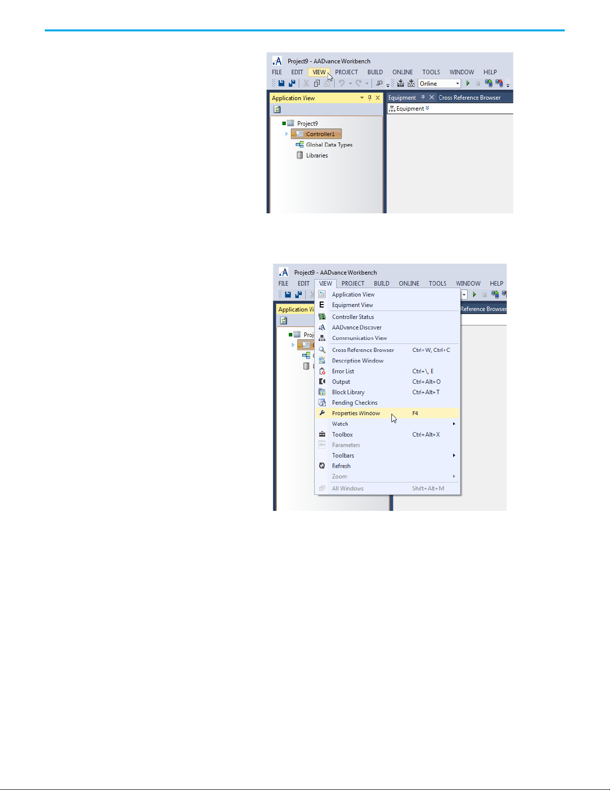
Chapter 4 Starting a Project and Defining the Controller
This will reveal the VIEW drop-down options menu, Which has
Properties Window as one of the list options.
Key board shortcut [F4] can also be used.
Left clicking the mouse with the cursor over the tab with the Properties legend
reveals the Controller Properties configuration options.
62 Rockwell Automation Publication ICSTT-RM458D-EN-P - February 2021
Page 63
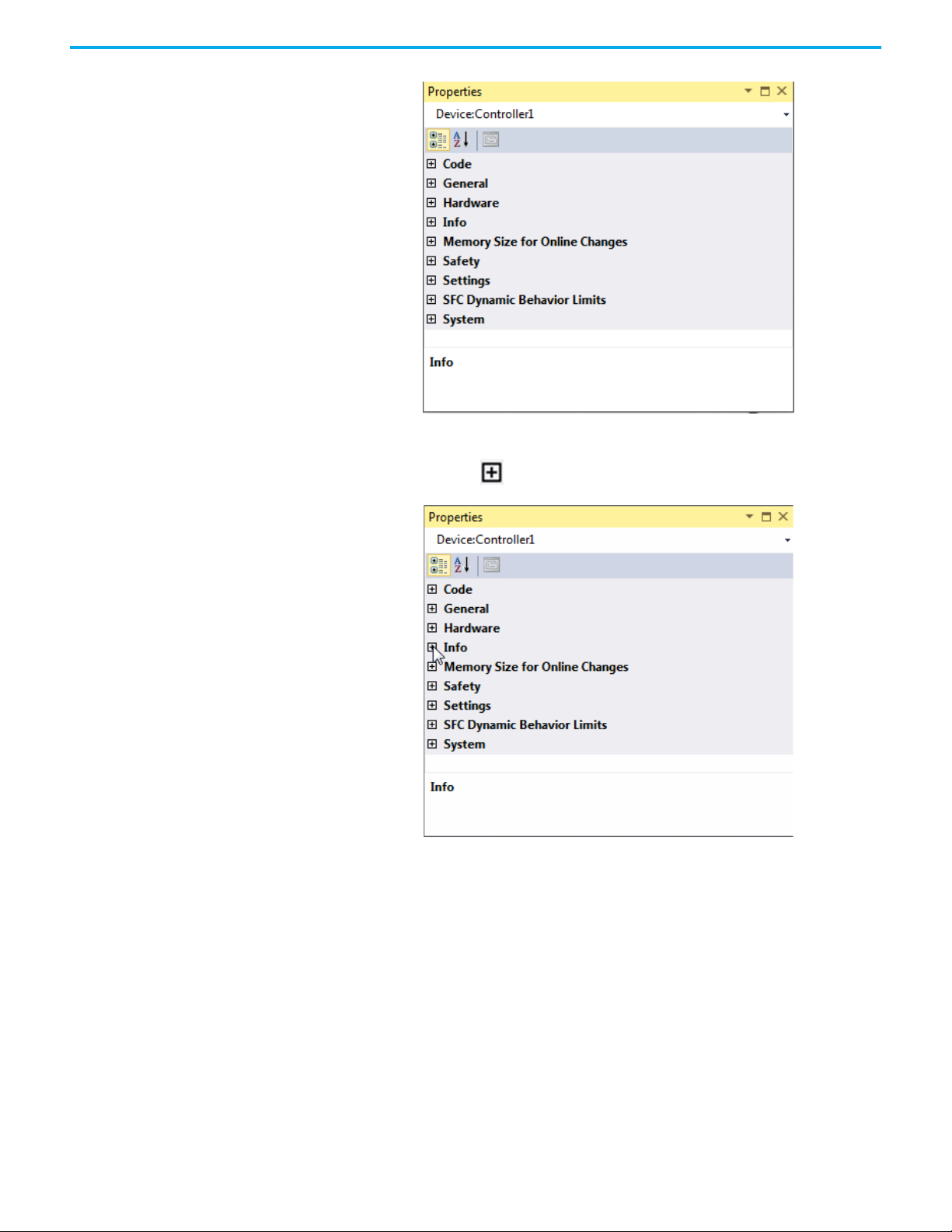
Chapter 4 Starting a Project and Defining the Controller
The options can be expanded by left clicking the mouse with the cursor over
the buttons with the legend.
The window will expand to reveal further options.
Rockwell Automation Publication ICSTT-RM458D-EN-P - February 2021 63
Page 64

Chapter 4 Starting a Project and Defining the Controller
Repeating the expansion for all available buttons reveals the full detail of the
Properties Window, which incorporates all the elements listed in the table
above.
Controller Process Safety Time
64 Rockwell Automation Publication ICSTT-RM458D-EN-P - February 2021
The process safety time (PST) defines the maximum time that the controller
lets its outputs stay in the ON state after the controller detects important
Page 65
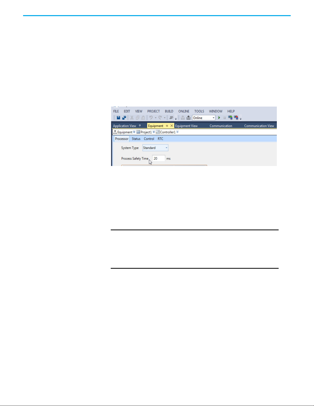
Chapter 4 Starting a Project and Defining the Controller
diagnostic or application faults. If the PST expires, the system sets its outputs
to their specified safe states.
You have to set the top-level PST for the controller. Each group of I/O modules
can inherit this setting or they can use their own setting as an alternative.
Configure the Top-level Process Safety Time
Choose a top-level process safety time which is larger than the application
execution time. If you set a process safety time less than the application
execution time, the application will not run.
Set the top-level process safety time:
1. Select View on the main tool-bar / menu bar.
2. Select Equipment View from the drop-down box.
3. Select and double-click the Controller that the user requires (the initial
default is Controller1).
4. A default value of 2,500 ms is shown. Enter the time value into the
Process Safety Time field. Choose from the following range of values:
•Minimum: 20 ms
• Maximum: 60,000 ms (which is 60 seconds or 1 minute)
IMPORTANT
5. Press Ctrl+S to save your changes.
A PST of 20 ms is not sufficient to let the controller run, short
PSTs must be tested, including testing the addition of
processors.
For a large installation, set the top-level PST to 1,500 ms (1.5 s) or
larger. This verifies that there is sufficient time for a second or
third processor module to educate.
Online Update You can modify a controller while it is operational and the application is
running by using an online update. This process enables you to change the I/O
configuration and the data and functions listed in the table. Changes to the
I/O configuration must follow the changes to the hardware Configuration.
The default setting for the Online update feature is enabled, however, the
online updates for I/O modifications is disabled by default. To perform an I/O
online update you must first enable the feature.
Rockwell Automation Publication ICSTT-RM458D-EN-P - February 2021 65
Page 66

Chapter 4 Starting a Project and Defining the Controller
Changes Available Using through an Online Update
Controller Data/Function Action
Bindings
Internal Variables
Programs
Functions and Function Blocks
I/O Channels
ATTENTION: Performing an online update can affect the Safety
Function of the system if the change is performed while the application
is running. A change should only be attempted if absolutely necessary.
Also, if the change is not performed correctly, the change can stop the
application. Therefore, before performing an online update alternative
safety measures should be implemented and be present for the duration
of the update.
Adding, deleting and editing:
• Creating and deleting bindings between variables.
• Changing the consume Status Variable and consumption behavior of a
binding. Changing the producing variable, consuming variable, or
network for a binding creates a new one.
• Adjusting the update timeout period in the network parameters. The
update timeout period is the maximum time during which the
consumer can remain in the update state.
Adding, deleting and editing internal variables:
• When renaming or changing the data type of internal variables, the
Workbench creates new variables. Therefore, variables are initialized.
• Changing the alias, initial value, group, scope, direction, retain setting
address, and comment of variables. When changing the initial values
of a read-only internal value, the Workbench reinitializes the variable.
When changing the scope of a variable, the Workbench reinitializes
the variable.
• Modifying the length of string variables. When decreasing the length,
the contents of the string is truncated to the new length.
• Switching a variable attribute between the input and output attribute.
You cannot switch variables between the internal and input/output
attribute.
• Adding and removing elements in arrays for internal variables. For
multi-dimensional arrays, you can only add elements to the first
dimension. The Workbench initializes these new elements. Adding
elements to other dimensions causes the Workbench to initialize a
new array.
• Renaming, adding variables, removing variables from the group to
which a variable belongs or moving the variable to another group.
Adding, deleting, renaming and reordering (for execution within the
programs section) programs.
• When renaming programs, the Workbench detects a CRC mismatch
and updates the code on the target for the program and reinitializes
all local variables. When renaming SFC programs instances data and
local variables are not preserved, i.e. elements are reset to their initial
state.
• When planning to add programs (other than SFC) using online changes,
you need to allocate a sufficient number of maximum extra POUs.
• Adding, deleting, renaming steps and transitions as well as modifying
the initial step or the flow between elements. When modifying SFC
programs, instance data and local variables is preserved, i.e. elements
are not reset to their initial state.
• Adding, deleting and moving action blocks within steps of SFC
programs. Action blocks within steps are executed in order of
appearance. You can also change the qualifier of an action block.
Adding, deleting and moving function blocks. Adding and deleting
function block instances.
• Renaming and modifying user-defined functions and function blocks.
• Adding, removing and modifying the parameters of user-defined
functions and function blocks. When modifying functions and function
blocks called by other POUs as well as the calling POUs.
Adding, deleting and modifying I/O channels.
• Changing the wired variables.
66 Rockwell Automation Publication ICSTT-RM458D-EN-P - February 2021
Page 67

Controller Data/Function Action
Adding, deleting and modifying I/O modules.
• Changing the wired variable. The gain and offset are configured by
I/O Modules
I/O Variables
I/O Configuration
setting the Raw/Engineering Min and Max vales.
• These online changes are only possible if the Update I/O Module Online
controller property is set to True.
Note: This is only possible on the analogue channels.
Adding, deleting and modifying I/O variables.
• Wiring, un-wiring and swapping I/O variables whose data type length
(string variables), dimensions (arrays) and address remains
unchanged. For these I/O variables you can modify the direction (input
or output only), scope, attribute (read, write or free), retain flag alias
and comment.
• When modifying the direction, I/O variables cannot change to or from
the internal type. Note that modifying the Equipment View causes the
values of new and removed output I/O variables to be reinitialized.
• Change the I/O configuration: remove a module, move a module to a
different slot, change a module or add a new module.
Chapter 4 Starting a Project and Defining the Controller
Archiving and Restoring Repository Projects
You can archive projects contained in a repository and you can restore projects
that were previously archived. Archiving a repository project means copying a
project and its modification history and placing it in a compressed file (.VSC).
You can restore a compressed file in another repository while retaining the
original modification history.
Projects archived from AADvance2.X workbench versions cannot be restored
in AADvance1.X workbench versions.
From the Application view, you can perform version control operations for all
elements. From the Communication and Equipment views, you can perform
version control operations for projects and controllers.
To archive a repository project
1. From the required view, select the project to archive.
2. From the File menu, choose Version Control, then Archive.
3. In the Archive dialog, indicate whether to archive the complete project
history or the latest project version, then click Archive.
4. In the Save As dialog, specify a name and browse for the storage location
for the archive file.
The default name and storage location for archive files is the project name and
folder.
To restore a repository project
1. From the File menu, choose New Project.
The New Project dialog is displayed.
2. Select Restore from the Project Types list, then Restore Project from an
Archive in the Templates list.
3. Click Browse.
4. In the Select Archive File dialog box, locate the project archive, then click
OK.
Rockwell Automation Publication ICSTT-RM458D-EN-P - February 2021 67
Page 68

Chapter 4 Starting a Project and Defining the Controller
5. In the New Project dialog box, click OK. The project is restored.
After clicking OK in the Select Archive File dialog box, you are returned to
the New Project dialog box.
Processor Module Battery and Alarm
The 9110 processor module has a battery that supports retained variables and
the real-time clock when the system power is switched off. The system has a
processor battery alarm to inform you when the battery voltage is too low and
you need to fit a new battery.
NOTE The Eurocard processor does not have a battery, and the battery
alarm is disabled by default.
Configure the Processor Battery Alarm
You can disable the battery alarm, for example for undersea and other
inaccessible systems not having a battery.
To set the battery alarm:
1. Select VIEW on the main tool-bar / menu bar.
2. Select Equipment View from the drop-down box.
3. Select and double-click the Controller that the user requires (the initial
default is Controller1).
4. Set the Type value for the Battery Alarm to Enabled or Disabled.
• The default value is Enabled for standard systems.
Remote Fault Reset The remote fault reset enables faults to be cleared on processor modules
without the need to physically press the Fault Reset button located on the
T9110 front panel. As well, you can use the remote fault reset to join processors
to a running system. The remote fault reset is required for sub-sea systems
since it is impossible to physically manipulate the processors. When enabling
Remote Fault Reset, a warning is displayed confirming that you want the
controller to be remotely reset.
68 Rockwell Automation Publication ICSTT-RM458D-EN-P - February 2021
Page 69

Chapter 4 Starting a Project and Defining the Controller
The default setting is disabled, which is 0x00000000. To enable, the
authentication key must be a non-zero hexadecimal value, ranging
0x00000001 to 0xFFFFFFFF.
Four output variables must be configured to trigger the reset/join. A
communication protocol must be able to write to the variables. For example,
when using Modbus, the variables must be configured with Modbus addresses
and “The Allow Modbus Write” must be enabled. Two of the variables are of
type WORD. When combined these two words must match the configured
authentication key before a remote reset/join will be permitted.
The two WORD outputs are wired to the Processor’s Control integers Allow
Remote Fault Reset MSB and Allow Remote Fault Reset LSB:
Rockwell Automation Publication ICSTT-RM458D-EN-P - February 2021 69
Page 70

Chapter 4 Starting a Project and Defining the Controller
Two Boolean outputs are also required. One to trigger a remote reset, the other
a join. These should be configured as Modbus coils:
The outputs should be wired to the Processor’s Control Booleans, Perform
Remote Fault Reset and Perform Remote Fault Join:
To perform a remote reset/join, the remote client must write the correct values
to the authentication key output variables, then cause a rising edge on either
the remote reset, or remote join Boolean.
70 Rockwell Automation Publication ICSTT-RM458D-EN-P - February 2021
Page 71

Chapter 5
Declaring Project Variables
Project variables can use the standard IEC 61131-3 data types, or you can define
your own, based on the IEC 61131-3 types. You can also define structures using
standard IEC 61131-3 types, arrays, and other user types. This chapter explains
how to create and adjust variables for your project.
About Variables The AADvance® Workbench maintains details of all your application variables.
You can define your variables at the start of a new project, or while creating a
program. Include processor and I/O module variables and the I/O channel
variables.
The AADvance Workbench automatically assigns a set of variable elements
when you select the data type.
Declare or Change Variables
Use the Variables window (dictionary) to declare new variables and to change
the properties of existing variables. Do the following:
1. Use the Application view to select the applicable variables. For example,
go the controller and then Variables to navigate to the Controller
Variables shown in the illustration.
2. Either, double-click Controller Variables or right-click Controller
Variables and then click Open.
• The Variables window opens in the content window.
You can also use the variable selector window to declare and change
variables. You can open the variable selector window from more than one
location, such as the MODBUS, OPC and SOE editors.
3. To declare a new variable, go to the bottom row of the grid (identified by
an '*') and enter the name of the variable, then set the Data Type from the
drop-down list.
Rockwell Automation Publication ICSTT-RM458D-EN-P - February 2021 71
Page 72

Chapter 5 Declaring Project Variables
4. If you set the Data Type to a structure, click the + symbol to show the
elements of the variable.
• The AADvance Workbench assigns a set of elements to match the
structure.
Properties for AADvance Project Variables
5. Define the general properties for the variable and for each element to use
in your application.
• You can define an array. When declaring the variable, use the
Dimension property to define the array.
• For Boolean variables, you can specify user text messages for the
FALSE and TRUE conditions.
• For string variables, you specify the string length in the String Size
property (Defaults to 80).
• For complex variables, wired elements set to read or write must have
the Attribute property set to Read/Write and the Direction set to the
applicable value.
• If you set the Direction of a variable to VarInput, you must set the
Attribute property to Read.
• If you set the Direction of a variable to VarOutput, you must set the
Attribute property to Write or Read/Write.
6. If you use the variable for MODBUS, OPC or SOE, use the
Communication view or the Equipment view to access the applicable
MODBUS, OPC, or SOE editor to define additional parameters.
7. To adjust an existing variable, change the variable properties.
Name: A unique name for the variable. The name must start with a letter or an
underscore character followed by letters, digits and single underscore
characters. The name cannot use two underscore characters one after the
other and must be less than 128 characters long.
• Example: di_full
Data Type: A standard IEC 61131 data type, AADvance (9K) structure, or a userdefined structure.
72 Rockwell Automation Publication ICSTT-RM458D-EN-P - February 2021
Page 73

Chapter 5 Declaring Project Variables
Dimension: The size (number of elements) of an array.
• Example: [1..4, 1..7]
String Size: The maximum number of characters the variable can contain, if
the Data Type is STRING. The maximum length of a string is 252 characters,
the last 3 bytes are reserved for maximum size (252), current length (1 to 252)
and the null/termination character.
Initial Value: Initial variable value, numeric or textual.
Direction: One of the following values:
• VarInput: A variable connected to an input device (refreshed by the
system)
• VarOutput: A variable connected to an output device
• Var: An internal variable updated by the programs or communication
Attribute: One of the following values:
• Read: A read-only variable with an initial value. The programs cannot
change the variable.
• Write: A write-only variable with an initial value. The programs can only
write to the variable.
• Read/Write: A variable that can be used for reading or writing.
Retained: TRUE or FALSE:
• TRUE: The controller stores the value in non-volatile memory and
restores the value if the controller stops and restarts.
If the processor battery voltage is too low or the battery is not fitted,
retained data will be lost, setting Retained to TRUE has no effect.
Comment: User comments. Not used by the application.
Alias: A name used in the ladder diagram and function block. The first part of
the text in the comment field, truncated at 16 characters or before the first ':'
character, whichever comes first.
Wiring: The I/O point to which the variable is wired to.
• The wiring property uses the syntax of a directly represented variable to
show a channel that is not linked to a declared variable.
• The identifier of a directly represented variable is always %.
• Example: %IXs.c; where 'I' is an input, 'X' is a Boolean, 's' is the address of
the module and 'c' is the channel number.
Allow OPC Write: Permits OPC clients to write to the variable (configured in
OPC view).
Groups: Group name, or none.
Message TRUE: A user text message for the TRUE value of a Boolean variable,
which can be used for Sequence of Events or OPC.
• Example: 'Pump on'.
Rockwell Automation Publication ICSTT-RM458D-EN-P - February 2021 73
Page 74

Chapter 5 Declaring Project Variables
Message FALSE: A user text message for the FALSE value of a Boolean variable,
which can be used for Sequence of Events or OPC.
• Example: 'Pump off'.
Standard IEC 61131-3 Data Types
You can declare variables using the following standard IEC 61131-3 data types.
Name Description
BOOL
BYTE
DATE Date value (32 bit)
DINT
DWORD Double word value (32 bit)
INT
LINT
LREAL
LWORD Long word value (64 bit)
REAL
SINT
STRING Character string having a defined size
(1)
TIME
UDINT
UINT
ULINT
USINT
WORD Word value (16 bit)
(1) The TIME data type cannot store dates.
Boolean logic (0 or 1), other value s: Off or On; False or True; Min or
Max
Byte value (8 bit); a group of binary digits or bits (usually eight)
operated on as a unit.A byte considered as a unit of memory size.
Signed (±) double integer continuous value (32 bit):
Values; -2147483648 to +2147483647
Signed (±) single integer continuous value (16 bit)
Values: -32768 to +32767
Long integer continuous value (64 bit)
Values: -9223372036854775808 to +9223372036854775807
Long real (floating) continuous value (64 bit) is quoted to 12
significant figures. This has three ranges as follows:
• -1.79769E+308 to -5.0E-324 (negative values)
•0
• +5.0 E-324 to +1.79769E+308 (positive values)
Real (floating) continuous value (32 bit) is quoted to six significant
figures. This has three ranges as follows:
• -3.402823E+38 to -1.4E-45 (negative values)
•0
• +1.14E-45 to +3.402823E+38 (positive values)
Signed (±) short integer continuous value (8 bit)
Values: -128 to +127
Time interval from 0 to 232 ms (32 bit)
Unsigned double integer continuous value (32 bit)
Values: 0 to 4294967295
Unsigned single integer continuous value (16 bit)
Values: 0 to 65535
Unsigned long integer continuous value (64 bit)
Values: 0 to 18446744073709551615
Unsigned short integer continuous value (8 bit)
Values: 0 to 255
Built-in Data Types You can declare variables using the following built-in data types, and also the
standard IEC 61131-3 data types.
FB types are used to declare function block instances. They are named sets of
data used by the function block.
Name Purpose or Application(s)
AVERAGE (FB Type) Running average over N samples
BLINK (FB Type) Blinking Boolean signal
CMP (FB Type) Full comparison function block
74 Rockwell Automation Publication ICSTT-RM458D-EN-P - February 2021
Page 75

Chapter 5 Declaring Project Variables
Name Purpose or Application(s)
CTD (FB Type) Down counter
CTU (FB Type) Up counter
CTUD (FB Type) Up-down counter
DERIVATE (FB Type) Differentiation according to time
F_TRIG (FB Type) Falling edge detection
HYSTER (FB Type) Boolean hysteresis on difference of reals
INTEGRAL (FB Type) Integration over time
KvbConsNetStatus (FB Type)
KvbProdNetStatus (FB Type)
LIM_ALRM (FB Type) High/low limit alarm with hysteresis
ModbusServiceStatus (FB Type) Modbus service status
R_TRIG (FB Type) Rising edge detection
RS (FB Type) Reset dominant bistable
SIG_GEN (FB Type) Signal generator
SoeServiceStatus (FB Type) Sequence of events service status
SR (FB Type) Set dominant bistable
STACKINT (FB Type) Stack of integer analogs
TOF (FB Type) Off-delay timing
TON (FB Type) On-delay timing
TP (FB Type) Pulse timing
CONNECTION_STATUS ControlLogix® CIP over Ethernet/IP consumed variable
T9K_AI_COMPACT 9000 series analogue input channel
T9K_AI_FULL 9000 series analogue input channel
T9K_AI_HART 9000 series HART data for analogue input channel
T9K_AI_HART_FULL 9000 series HART data for analogue input channel
T9K_AO_COMPACT 9000 series analogue output channel
T9K_AO_FULL 9000 series analogue output channel
T9K_DI_COMPACT 9000 series digital input channel
T9K_DI_FULL 9000 series digital input channel
T9K_DO_COMPACT 9000 series digital output channel
T9K_DO_FULL 9000 series digital output channel
T9K_FI_COMPACT 9000 series frequency input channel
T9K_FI_FULL 9000 series frequency input channel
T9K_TA_GROUP_STATUS 9000 series module status data
Function Block (FB) to get status of a network link to a producer
address
Function Block (FB) to get status of a network link to a consumer
address
Rockwell Automation Publication ICSTT-RM458D-EN-P - February 2021 75
Page 76

Chapter 5 Declaring Project Variables
Notes:
76 Rockwell Automation Publication ICSTT-RM458D-EN-P - February 2021
Page 77
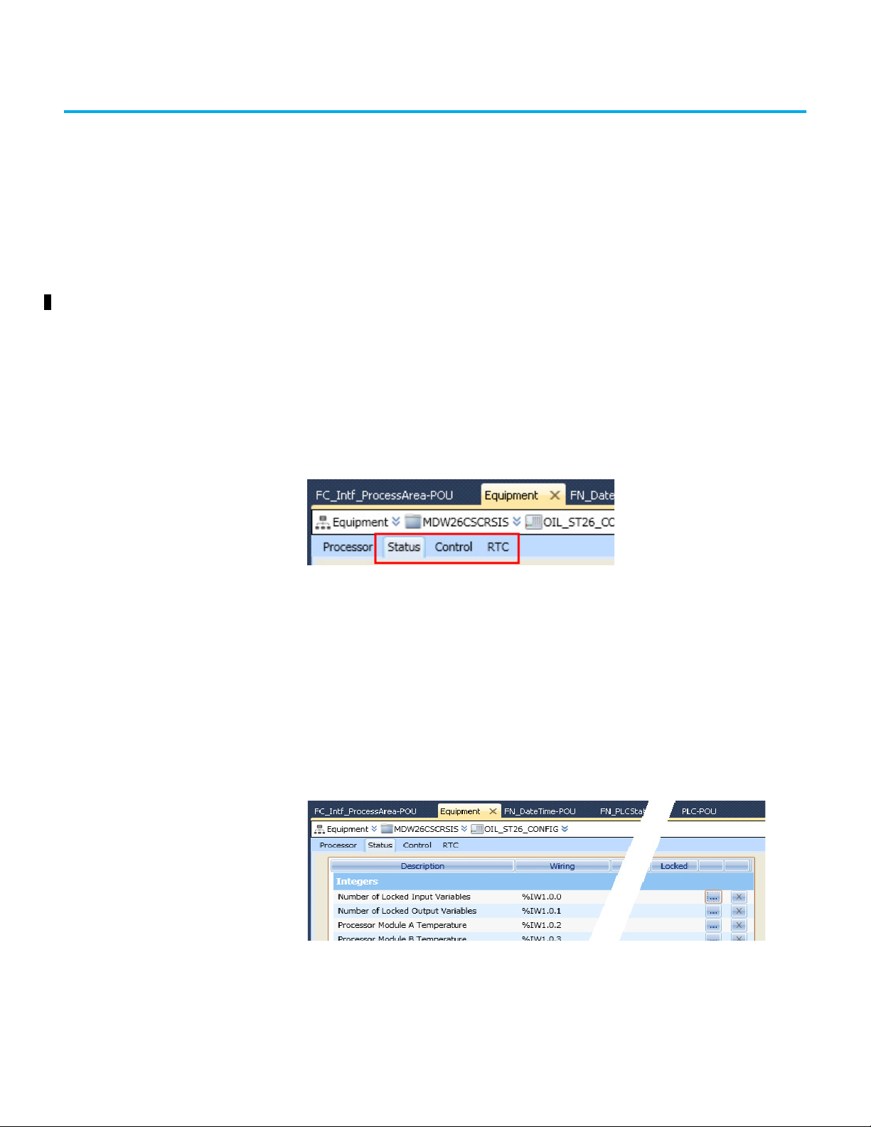
Chapter 6
Setting Processor Variables
This chapter describes the processor variables and explains how to set up and
use them in your application. The procedures use the Equipment View in the
AADvance® Workbench.
Processor Variables The 9110 processor module has status and control variables for use by the
application. Status variables get data from the processor module, and control
variables set data in the processor module.
The AADvance Workbench presents the processor variables in three tabs on
the Equipment tab of the content window:
To Wire a Processor Variable
•The Status tab holds status integers and status Booleans, which supply
data about the controller for the application;
•The Control tab holds control integers and control Booleans enabling the
application to send data to the controller;
•The RTC tab holds variables for the real-time clock: status variables,
program variables and control variables. Status variable supply date/time
data to the application. Program variables hold date/time data to be
written to the real-time clock. Control variables control updates to the
clock and set the clock.
To wire a 9110 processor variable:
1. From the Equipment view, double-click the required controller.
The ‘Equipment Property’ page is displayed.
2. From the Equipment Property page, click one of the following tabs:
• Status
• Control
Rockwell Automation Publication ICSTT-RM458D-EN-P - February 2021 77
Page 78

Chapter 6 Setting Processor Variables
•RTC
Each tab displays different processor variables performing specific
functions.
3. From the Processor Variable tab, locate the required variable and in the
wire column click .
The ‘Variable Selector’ is displayed.
4. From the ‘Variable Selector’ select the required variable and click OK.
The ‘Processor Variable’ is now wired.
To Unwire a Processor Variable
1. From the Equipment view, double-click the required controller.
The ‘Equipment Property’ page is displayed.
2. From the ‘Equipment Property’ page, click one of the following tabs:
• Status
• Control
•RTC
3. From the Processor Variable tab, locate the wired variable and in the
‘Unwire’ column click .
The Processor Variable is unwired.
Status Variables The Status Variables include:
1. Status Integers, which comprise
• Number of Locked Input Variables
• Number of Locked Output Variables
• Processor Module A Temperature
• Processor Module B Temperature
• Processor Module C Temperature.
2. Status Booleans, which comprise
• System Health
• System Health Reset, Voted 1 out of 3 (1oo3)
• Dongle detected (Voted)
• Processor Module A online
• Processor Module B online
• Processor Module C online
• Processor Module A Health
• Processor Module B Health
• Processor Module C Health
• Processor Module A 24 v1 Power Feed Health
• Processor Module B 24 v1 Power Feed Health
• Processor Module C 24 v1 Power Feed Health
• Processor Module A 24 v2 Power Feed Health
• Processor Module B 24 v2 Power Feed Health
• Processor Module C 24 v2 Power Feed Health
• Processor Module A Ready
• Processor Module B Ready
• Processor Module C Ready
78 Rockwell Automation Publication ICSTT-RM458D-EN-P - February 2021
Page 79
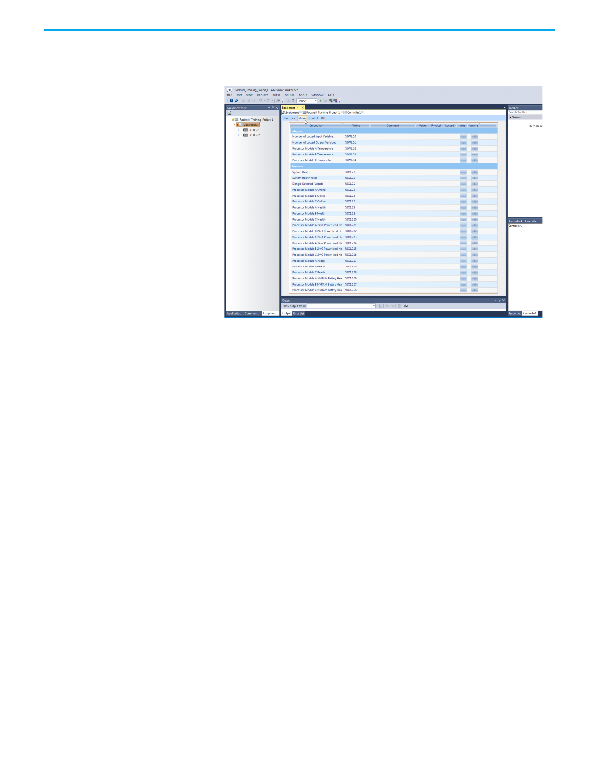
Chapter 6 Setting Processor Variables
• Processor Module A NVRAM Battery Health
• Processor Module B NVRAM Battery Health
• Processor Module C NVRAM Battery Health.
Status Integers The Status Integers supply data about the controller to the application
Number of Locked Input Variables
Direction: input to application from controller
Type: word
Values:
•0 to 65,535
Description:
Reports the quantity of input variables having been locked by the user. The top
limit of 65,535 represents the capacity of the variable; the real limit is the
number of variables in the application.
Number of Locked Output Variables
Direction: input to application from controller
Type: word
Values:
•0 to 65,535
Rockwell Automation Publication ICSTT-RM458D-EN-P - February 2021 79
Page 80

Chapter 6 Setting Processor Variables
Description:
Reports the quantity of output variables having been locked by the user. The
top limit of 65,535 represents the capacity of the variable; the real limit is the
number of variables in the application.
Processor Module A Temperature
Direction: input to application from controller
Type: word
Values:
•0 to 65,535
Description:
Reports the temperature of the 9110 processor module in the given slot in
degrees centigrade. Set to 0 (zero) if no processor module is present.
Processor Module B Temperature
Direction: input to application from controller
Type: word
Values:
•0 to 65,535
Description:
Reports the temperature of the 9110 processor module in the given slot in
degrees centigrade. Set to 0 (zero) if no processor module is present.
Processor Module C Temperature
Direction: input to application from controller
Type: word
Values:
•0 to 65,535
Description:
Reports the temperature of the 9110 processor module in the given slot in
degrees centigrade. Set to 0 (zero) if no processor module is present.
Status Booleans The Status Booleans supply data about the controller to the application.
80 Rockwell Automation Publication ICSTT-RM458D-EN-P - February 2021
Page 81

Chapter 6 Setting Processor Variables
System Health
Direction: Input to application from controller
Type: Boolean
Values:
• TRUE = All installed processor and I/O modules are healthy and System
Health variable is FALSE (See Control Booleans). The processor module
System Healthy LED is green.
• FALSE = One or more of the installed processors and/or I/O modules are
reporting a module health problem or the System Health variable is
TRUE (See Control Booleans). The processor module System Healthy
LED is red.
NOTE The System Health alarm can be reset after a fault in a system
having at least one healthy processor or I/O module in a module
group.
System Health Reset (Voted 1oo3)
Direction: input to application from controller
Type: Boolean
Values:
•TRUE = The Fault Reset button on a 9110 processor module has been
pressed in the cycle before.
•FALSE = No Fault Reset button is active.
The default value is FALSE.
Description:
Reports that the Fault Reset button on a processor module has been pressed.
The system health reset is triggered by pressing the button but the value does
not change to TRUE until the start of the next application cycle. The value
remains TRUE for the cycle and then reverts to FALSE even if the button has
been pressed throughout.
Dongle Detected (Voted)
Direction: input to application from controller
Type: Boolean
Values:
• TRUE = One or more 9110 processor modules can see a program enable
key at the KEY connector on the 9100 processor base unit.
• FALSE = No processor module can see a program enable key.
Rockwell Automation Publication ICSTT-RM458D-EN-P - February 2021 81
Page 82

Chapter 6 Setting Processor Variables
Description:
Reports the presence or absence of a program enable key.
Processor Module A Online
Direction: input to application from controller
Type: Boolean
Values:
• TRUE = The 9110 processor module in the given slot is online
• FALSE = The processor module is offline
The default value is TRUE
Description:
Reports that a processor module in a dual or triple modular redundant
configuration is present and is communicating through the inter-processor
link to one or both of its peers. Reports that a simplex processor module is
present.
Processor Module B Online
Direction: input to application from controller
Type: Boolean
Values:
• TRUE = The 9110 processor module in the given slot is online
• FALSE = The processor module is offline
The default value is TRUE
Description:
Reports that a processor module in a dual or triple modular redundant
configuration is present and is communicating through the inter-processor
link to one or both of its peers. Reports that a simplex processor module is
present.
Processor Module C Online
Direction: input to application from controller
Type: Boolean
Values:
• TRUE = The 9110 processor module in the given slot is online
• FALSE = The processor module is offline
82 Rockwell Automation Publication ICSTT-RM458D-EN-P - February 2021
Page 83

Chapter 6 Setting Processor Variables
The default value is TRUE
Description:
Reports that a processor module in a dual or triple modular redundant
configuration is present and is communicating through the inter-processor
link to one or both of its peers. Reports that a simplex processor module is
present.
Processor Module A Health
Direction: input to application from controller
Type: Boolean
Values:
• TRUE = The 9110 processor module in the given slot is healthy and its
Healthy LED indicator is green.
• FALSE = The processor module is faulty and its Healthy LED indicator is
red.
Description:
Reports the health status of a processor module.
Processor Module B Health
Direction: input to application from controller
Type: Boolean
Values:
• TRUE = The 9110 processor module in the given slot is healthy and its
Healthy LED indicator is green.
• FALSE = The processor module is faulty and its Healthy LED indicator is
red.
Description:
Reports the health status of a processor module.
Processor Module C Health
Direction: input to application from controller
Type: Boolean
Values:
• TRUE = The 9110 processor module in the given slot is healthy and its
Healthy LED indicator is green.
• FALSE = The processor module is faulty and its Healthy LED indicator is
red.
Rockwell Automation Publication ICSTT-RM458D-EN-P - February 2021 83
Page 84

Chapter 6 Setting Processor Variables
Description:
Reports the health status of a processor module.
Processor Module A 24 V1 Power Feed Health
Direction: input to application from controller
Type: Boolean
Values:
• TRUE = power feed voltage is within specifications (18 to 32 Vdc).
• FALSE = power feed is outside specifications.
Description:
Reports the health of power feed 1 (nominal 24 Vdc) to the 9110 processor
module in the given slot.
Processor Module B 24 V1 Power Feed Health
Direction: input to application from controller
Type: Boolean
Values:
• TRUE = power feed voltage is within specifications (18 to 32 Vdc).
• FALSE = power feed is outside specifications.
Description:
Reports the health of power feed 1 (nominal 24 Vdc) to the 9110 processor
module in the given slot.
Processor Module C 24 V1 Power Feed Health
Direction: input to application from controller
Type: Boolean
Values:
• TRUE = power feed voltage is within specifications (18 to 32 Vdc).
• FALSE = power feed is outside specifications.
Description:
Reports the health of power feed 1 (nominal 24 Vdc) to the 9110 processor
module in the given slot.
84 Rockwell Automation Publication ICSTT-RM458D-EN-P - February 2021
Page 85

Chapter 6 Setting Processor Variables
Processor Module A 24 V2 Power Feed Health
Direction: input to application from controller
Type: Boolean
Values:
• TRUE = power feed voltage is within specifications (18 to 32 Vdc).
• FALSE = power feed is outside specifications.
Description:
Reports the health of power feed 2 (nominal 24 Vdc) to the 9110 processor
module in the given slot.
Processor Module B 24 V2 Power Feed Health
Direction: input to application from controller
Type: Boolean
Values:
• TRUE = power feed voltage is within specifications (18 to 32 Vdc).
• FALSE = power feed is outside specifications.
Description:
Reports the health of power feed 2 (nominal 24 Vdc) to the 9110 processor
module in the given slot.
Processor Module C 24 V2 Power Feed Health
Direction: input to application from controller
Type: Boolean
Values:
• TRUE = power feed voltage is within specifications (18 to 32 Vdc).
• FALSE = power feed is outside specifications.
Description:
Reports the health of power feed 2 (nominal 24 Vdc) to the 9110 processor
module in the given slot.
Processor Module A Ready
Direction: input to application from controller
Type: Boolean
Rockwell Automation Publication ICSTT-RM458D-EN-P - February 2021 85
Page 86

Chapter 6 Setting Processor Variables
Values:
• TRUE = The 9110 processor module in the given slot is synchronized (see
description).
• FALSE = The processor module is out of synchronization or missing.
Description:
Reports that a processor module in a dual or triple modular redundant
configuration is present and is synchronized with one or both of its peers.
Reports that a simplex processor module is present.
Processor Module B Ready
Direction: input to application from controller
Type: Boolean
Values:
• TRUE = The 9110 processor module in the given slot is synchronized (see
description).
• FALSE = The processor module is out of synchronization or missing.
Description:
Reports that a processor module in a dual or triple modular redundant
configuration is present and is synchronized with one or both of its peers.
Reports that a simplex processor module is present.
Processor Module C Ready
Direction: input to application from controller
Type: Boolean
Values:
• TRUE = The 9110 processor module in the given slot is synchronized (see
description).
• FALSE = The processor module is out of synchronization or missing.
Description:
Reports that a processor module in a dual or triple modular redundant
configuration is present and is synchronized with one or both of its peers.
Reports that a simplex processor module is present.
Processor Module A NVRAM Battery Health
Direction: input to application from controller
Type: Boolean
Values:
86 Rockwell Automation Publication ICSTT-RM458D-EN-P - February 2021
Page 87

Chapter 6 Setting Processor Variables
• TRUE = The backup battery in the 9110 processor module in the given slot
is present and its voltage is within satisfactory limits.
• FALSE = The voltage of the backup battery is low or the battery is not
there.
Description:
Reports the health status of the backup battery in a processor module. The
battery voltage is checked at start up, then tested again every 24 hours (elapsed
time).
Processor Module B NVRAM Battery Health
Direction: input to application from controller
Type: Boolean
Values:
• TRUE = The backup battery in the 9110 processor module in the given slot
is present and its voltage is within satisfactory limits.
• FALSE = The voltage of the backup battery is low or the battery is not
there.
Description:
Reports the health status of the backup battery in a processor module. The
battery voltage is checked at start up, then tested again every 24 hours (elapsed
time).
Processor Module C NVRAM Battery Health
Direction: input to application from controller
Type: Boolean
Values:
• TRUE = The backup battery in the 9110 processor module in the given slot
is present and its voltage is within satisfactory limits.
• FALSE = The voltage of the backup battery is low or the battery is not
there.
Description:
Reports the health status of the backup battery in a processor module. The
battery voltage is checked at start up, then tested again every 24 hours (elapsed
time).
Control Variables Control variables include Control Integers and Control Booleans.
Rockwell Automation Publication ICSTT-RM458D-EN-P - February 2021 87
Page 88

Chapter 6 Setting Processor Variables
Control Integers The Control Integers let the application send instructions to the controller.
AUX LED Colour
Direction: output from application to controller
Type: word
Values:
• 0..3 (0 = off, 1 = red, 2 = green, 3 = amber)
•Default 0
Description:
Sets the state of the LED indicator labeled 'Aux' on all 9110 processor modules.
Allow Remote Fault Reset Most Significant Bits (MSB)
Direction: output from the application to the controller
Type: word
Values: Possible values range from 0 to 65535
Description:
Used in combination with Allow Remote Fault Reset LSB, enables remotely
resetting a processor or enables joining a processor to a running system. For a
successful remote fault reset or join, the value entered for the Remote Fault
Reset must match the combined values set for the control integers Allow
Remote Fault Reset MSB and Allow Remote Fault Reset LSB. Also, the control
booleans Perform Remote Fault Reset and Perform Remote Fault Join must be
set to TRUE.
88 Rockwell Automation Publication ICSTT-RM458D-EN-P - February 2021
Page 89

Chapter 6 Setting Processor Variables
Allow Remote Fault Reset Least Significant Bits (LSB)
Direction: output from the application to the controller
Type: word
Values: Possible values range from 0 to 65535
Description:
Used in combination with Allow Remote Fault Reset MSB, enables remotely
resetting a processor or enables joining a processor to a running system. For a
successful remote fault reset or join, the value entered for the Remote Fault
Reset must match the combined values set for the Control Integers Allow
Remote Fault Reset MSB and Allow Remote Fault Reset LSB. Also, the Control
Booleans Perform Remote Fault Reset and Perform Remote Fault Join must be
set to TRUE.
Control Booleans The Control Booleans let the application send instructions to the controller.
Unlock All Locked Variables
Direction: output from application to controller
Type: Boolean
Values:
• TRUE = Remove all locks.
• FALSE = No effect.
The default value is FALSE
Description:
Removes all user locks on input and output variables.
Set System Health Alarm
Direction: output from application to controller.
Type: Boolean
Values:
• TRUE = When the variable transitions from FALSE to TRUE, the system
responds as if it had found a system level fault. The processor module
System Healthy LED is set to RED and the System Health Boolean is set
TRUE. When the variable is TRUE, the fault is immediately reannunciated after pressing the Fault Reset button.
• FALSE = Does not send an alarm signal to the controller. After the
variable transitions from TRUE to FALSE, the processor module System
Healthy LED passes to GREEN after pressing the Fault Reset button.
Rockwell Automation Publication ICSTT-RM458D-EN-P - February 2021 89
Page 90

Chapter 6 Setting Processor Variables
The default value is FALSE
Description:
Sends a System Health alarm signal from the application to the controller.
HART Pass-Through
Direction: output from application to controller
Type: Boolean
Values:
• TRUE = HART Pass-Through is enabled and available for an Analog
Module.
• FALSE = HART Pass-Through is disabled and not available.
The default value is FALSE
Description:
Starts the HART Pass-Through feature and allows HART messages on analog
input and output modules. The system allows messages on each channel
independently and together.
Perform Remote Fault Reset
Direction: output from the application to the controller
Type: Boolean
Values:
• TRUE - Resets the faulty processors
• FALSE - Remotely resetting processors is disabled
The default value is FALSE
Description:
When a rising edge is detected, resets the faulty processors
Perform Remote Fault Join
Direction: output from the application to the controller
Type: Boolean
Values:
• TRUE - The processors join the running system
• FALSE - Remotely joining processors to a running system is disabled.
The default value is FALSE
90 Rockwell Automation Publication ICSTT-RM458D-EN-P - February 2021
Page 91

Chapter 6 Setting Processor Variables
Description:
When a rising edge is detected, the processors join the running system
Real-Time Clock The AADvance controller contains a real-time clock (RTC) used to make a
record of the time and date of system events, SOE services, and log files. You
can manually set the real-time clock of the processor by using RTC variables or
use SNTP from the Communication View.
IMPORTANT
You are strongly recommended to use SNTP to synchronize
controllers so that all time-related events, services, and logs use
the same time of day.
RTC Processor Variables RTC processor variables manage information regarding the real-time clock.
The AADvance controller has the following RTC processor variables:
• RTC Status Variables: Year, Month, Day of Month, Hours, Minutes,
Seconds, Milliseconds
• RTC Program Variables: Year, Month, Day of Month, Hours, Minutes,
Seconds, Milliseconds
• RTC Control Variables: RTC Write, RTC Read, Year, Month, Day of
Month, Hours, Minutes, Seconds, Milliseconds
RTC Status Variables The RTC Status Variables supply data about the controller real-time clock to
the application.
RTC Status: Year
Direction: input to application from controller
Type: word
Values:
• 2,000 to 2,399, or 0 (see description)
Description:
Reports the oldest value of real-time clock (RTC) Year as voted by every 9110
processor module which is present and synchronized. Only updated if the realtime clock control Boolean RTC Read is set to TRUE. If RTC Read is FALSE, the
value will be 0 (zero).
RTC Status: Month
Direction: input to application from controller
Type: word
Values:
Rockwell Automation Publication ICSTT-RM458D-EN-P - February 2021 91
Page 92

Chapter 6 Setting Processor Variables
• 1 to 12, or 0 (see description)
Description:
Reports the oldest value of real-time clock (RTC) month as voted by every 9110
processor module which is present and synchronized. Only updated if the realtime clock control Boolean RTC Read is set to TRUE. If RTC Read is FALSE, the
value will be 0 (zero).
RTC Status: Day of Month
Direction: input to application from controller
Type: word
Values:
• 1 to 31, or 0 (see description)
Description:
Reports the oldest value of real-time clock (RTC) day of month as voted by
every 9110 processor module which is present and synchronized. Only updated
if the real-time clock control Boolean RTC Read is set to TRUE. If RTC Read is
FALSE, the value will be 0 (zero).
RTC Status: Hours
Direction: input to application from controller
Type: word
Values:
•0 to 23
Description:
Reports the oldest value of real-time clock (RTC) hours as voted by every 9110
processor module which is present and synchronized. Only updated if the realtime clock control Boolean RTC Read is set to TRUE. If RTC Read is FALSE, the
value will be 0 (zero).
RTC Status: Minutes
Direction: input to application from controller
Type: word
Values:
•0 to 59
Description:
Reports the oldest value of real-time clock (RTC) minutes as voted by every 9110
92 Rockwell Automation Publication ICSTT-RM458D-EN-P - February 2021
Page 93

Chapter 6 Setting Processor Variables
processor module which is present and synchronized. Only updated if the realtime clock control Boolean RTC Read is set to TRUE. If RTC Read is FALSE, the
value will be 0 (zero).
RTC Status: Seconds
Direction: input to application from controller
Type: word
Values:
•0 to 59
Description:
Reports the oldest value of real-time clock (RTC) seconds as voted by every 9110
processor module which is present and synchronized. Only updated if the realtime clock control Boolean RTC Read is set to TRUE. If RTC Read is FALSE, the
value will be 0 (zero).
RTC Status: Milliseconds
Direction: input to application from controller
Type: word
Values:
•0 to 999
Description:
Reports the oldest value of real-time clock (RTC) milliseconds as voted by every
9110 processor module which is present and synchronized. Only updated if the
real-time clock control Boolean RTC Read is set to TRUE. If RTC Read is
FALSE, the value will be 0 (zero).
RTC Program Variables The RTC program variables contain the parts of the date to write to the real-
time clock when the RTC control variable RTC Write is asserted TRUE. The
values are written only if the RTC control variable Year is TRUE.
RTC Program: Year
Direction: output from application to controller
Type: word
Values:
• 2,000 to 2,399
• Default 0 (zero)
Rockwell Automation Publication ICSTT-RM458D-EN-P - February 2021 93
Page 94

Chapter 6 Setting Processor Variables
Description:
Specifies the Year part of the date to write to the real-time clock the next time
the RTC control variable RTC Write is asserted TRUE. The value is written only
if the RTC control variable Year is TRUE.
RTC Program: Month
Direction: output from application to controller
Type: word
Values:
•1 to 12
• Default 0 (zero)
Description:
Specifies the number of the month part of the date to write to the real-time
clock the next time the RTC control variable RTC Write is asserted TRUE. The
value is written only if the RTC control variable Month is TRUE.
RTC Program: Day of Month
Direction: output from application to controller
Type: word
Values:
•1 to 31
• Default 0 (zero)
Description:
Specifies the day of month part of the date to write to the real-time clock the
next time the RTC control variable RTC Write is asserted TRUE. The value is
written only if the RTC control variable Day of Month is TRUE.
RTC Program: Hours
Direction: output from application to controller
Type: word
Values:
•0 to 23
• Default 0 (zero)
Description:
Specifies the time of day (in hours) part of the date to write to the real-time
94 Rockwell Automation Publication ICSTT-RM458D-EN-P - February 2021
Page 95

Chapter 6 Setting Processor Variables
clock the next time the RTC control variable RTC Write is asserted TRUE. The
value is written only if the RTC control variable Hours is TRUE.
RTC Program: Minutes
Direction: output from application to controller
Type: word
Values:
•0 to 59
• Default 0 (zero)
Description:
Specifies the minute in the hour part of the date to write to the real-time clock
the next time the RTC control variable RTC Write is asserted TRUE. The value
is written only if the RTC control variable Minutes is TRUE.
RTC Program: Seconds
Direction: output from application to controller
Type: word
Values:
•0 to 59
• Default 0 (zero)
Description:
Specifies the second in the minute part of the date to write to the real-time
clock the next time the RTC control variable RTC Write is asserted TRUE. The
value is written only if the RTC control variable Seconds is TRUE.
RTC Program: Milliseconds
Direction: output from application to controller
Type: word
Values:
•0 to 999
• Default 0 (zero)
Description:
Specifies the milliseconds in the second part of the date to write to the realtime clock the next time the RTC control variable RTC Write is asserted TRUE.
The value is written only if the RTC control variable Milliseconds is TRUE.
Rockwell Automation Publication ICSTT-RM458D-EN-P - February 2021 95
Page 96

Chapter 6 Setting Processor Variables
RTC Control Variables The RTC control variables permit updates to the parts of the date in real-time
clock.
RTC Control: RTC Write
Direction: output from application to controller
Type: Boolean
Values:
• TRUE = Applies new values to real-time clock (see description).
• FALSE = No effect.
The default value is FALSE.
Description:
Sets new values for the real-time clock. There are seven values, all specified by
the RTC program control words Year, Month, Day of Month, Hours, Minutes,
Seconds and Milliseconds. Each value is set only if its related RTC control
variable (which is a Boolean, and similarly named Year, Month, Day of Month,
Hours, Minutes, Seconds or Milliseconds) is TRUE.
The change is started by the transition of the variable from FALSE to TRUE. If
the application holds the TRUE state until the end of the application cycle (or
longer), the application makes the change at the end of the cycle. There is no
time limit on returning the value from TRUE to FALSE after the clock is
updated. If the application returns the variable to FALSE before the end of the
application cycle, the clock is not updated.
Example
Consider this scenario:
• The date is 28th October 2008, 8 hours, 12 minutes and 35 seconds
• RTC Control RTC Read is TRUE
• RTC Control Year, Month and Day of Month are TRUE
• RTC Control Hours, Minutes and Seconds are TRUE.
The RTC Status Variables is returned, and the real-time clock is set as follows:
•Year = 2008
•Month = 10
•Day of Month = 28
•Hours = 8
•Minutes = 12
• Seconds = 35.
RTC Control: RTC Read
Direction: output from application to controller
96 Rockwell Automation Publication ICSTT-RM458D-EN-P - February 2021
Page 97

Chapter 6 Setting Processor Variables
Type: Boolean
Values:
• TRUE = The controller updates RTC status values on each application
cycle.
• FALSE = RTC status values are static (do not update).
The default value is FALSE
Description:
Checks if the RTC Status Variables (RTC Status: Year, RTC Status: Month, RTC
Status: Day of Month, RTC Status: Hours, RTC Status: Minutes and RTC
Status: Seconds) updates in real-time.
All the RTC Status Variables must be set to TRUE when the RTC Read variable
is set to TRUE, otherwise the RTC value is not updated and reported.
RTC Control: Year
Direction: output from application to controller
Type: Boolean
Values:
• TRUE = RTC program Year is applied by RTC Write
• FALSE = RTC program Year is ignored
The default is FALSE until an initial value is specified in the application.
Description:
Checks if the value of the RTC program variable named Year must be applied to
the real-time clock the next time the RTC control variable named RTC Write is
set to TRUE.
The RTC program variable is only updated if the RTC control variable RTC
Read is set to TRUE and all other RTC Control variables are set to TRUE.
RTC Control: Month
Direction: output from application to controller
Type: Boolean
Values:
• TRUE = RTC program month is applied by RTC Write.
• FALSE = RTC program month is ignored.
The default value is FALSE until an initial value is specified in the application.
Rockwell Automation Publication ICSTT-RM458D-EN-P - February 2021 97
Page 98

Chapter 6 Setting Processor Variables
Description:
Checks if the value of the RTC program variable named Month must be applied
to the real-time clock the next time the RTC control variable named RTC Write
is set to TRUE.
The RTC program variable is only updated if the RTC control variable RTC
Read is set to TRUE and all other RTC Control variables are set to TRUE.
RTC Control: Day of Month
Direction: output from application to controller
Type: Boolean
Values:
• TRUE = RTC program day of month is applied by RTC Write.
• FALSE = RTC program day of month is ignored.
The default value is FALSE until an initial value is specified in the application.
Description:
Checks if the value of the RTC program variable named Day of Month must be
applied to the real-time clock the next time the RTC control variable named
RTC Write is set to TRUE.
The RTC program variable is only updated if the RTC control variable RTC
Read is set to TRUE and all other RTC Control variables are set to TRUE.
RTC Control: Hours
Direction: output from application to controller
Type: Boolean
Values:
• TRUE = RTC program hours is applied by RTC Write
• FALSE = RTC program hours is ignored
The default value is FALSE until an initial value is specified in the application.
Description:
Checks if the value of the RTC program variable named Hours must be applied
to the real-time clock the next time the RTC control variable named RTC Write
is set to TRUE.
The RTC program variable is only updated if the RTC control variable RTC
Read is set to TRUE and all other RTC Control variables are set to TRUE.
98 Rockwell Automation Publication ICSTT-RM458D-EN-P - February 2021
Page 99

Chapter 6 Setting Processor Variables
RTC Control: Minutes
Direction: output from application to controller
Type: Boolean
Values:
• TRUE = RTC program minutes is applied by RTC Write.
• FALSE = RTC program minutes is ignored.
The default value is FALSE until an initial value is specified in the application.
Description:
Checks if the value of the RTC program variable named Minutes must be
applied to the real-time clock the next time the RTC control variable named
RTC Write is set to TRUE.
The RTC program variable is only updated if the RTC control variable RTC
Read is set to TRUE and all other RTC Control variables are set to TRUE.
RTC Control: Seconds
Direction: output from application to controller
Type: Boolean
Values:
• TRUE = RTC program seconds is applied by RTC Write
• FALSE = RTC program seconds is ignored
The default value is FALSE until an initial value is specified in the application.
Description:
Checks if the value of the RTC program variable named Seconds must be
applied to the real-time clock the next time the RTC control variable named
RTC Write is set to TRUE.
The RTC program variable is only updated if the RTC control variable RTC
Read is set to TRUE and all other RTC Control variables are set to TRUE.
RTC Control: Milliseconds
Direction: output from application to controller
Type: Boolean
Values:
• TRUE = RTC program milliseconds is applied by RTC Write
Rockwell Automation Publication ICSTT-RM458D-EN-P - February 2021 99
Page 100

Chapter 6 Setting Processor Variables
• FALSE = RTC program milliseconds is ignored
The default value is FALSE until an initial value is specified in the application.
Description:
Checks if the value of the RTC program variable named Milliseconds must be
applied to the real-time clock the next time the RTC control variable named
RTC Write is set to TRUE.
The RTC program variable is only updated if the RTC control variable RTC
Read is set to TRUE and all other RTC Control variables are set to TRUE.
To manually set the realtime clock
You manually set the real-time clock of the processor by using RTC variables.
1. From the Build menu, click Build All.
2. From the Project menu, either click Download or Update.
3. From the Online menu, click Connect.
4. Force the following RTC Control Variables to TRUE:
RTC Read, Year, Month, Day of Month, Hours, Minutes, Seconds, and
Milliseconds.
IMPORTANT
The RTC Status Variables now display the current date and time in the
processor.
5. Double-click each RTC Program Variable (Year, Month, Day of Month,
Hours, Minutes, Seconds, and Milliseconds), specify a value, and then
click Write.
6. To enable writing the new date and time to the processor, set RTC Write
to TRUE and then FALSE.
The RTC Status Variables now display the set date and time in the processor.
Do not force RTC Write at this point, the value should be FALSE.
100 Rockwell Automation Publication ICSTT-RM458D-EN-P - February 2021
 Loading...