

Page 1

TrustedTM
PD-T8891
TM
Trusted
Speed Monitor OFTA (SOFTA)
Introduction
M
T
The Trusted
piece of equipment. It provides the output field interface for one rotating machine group when used as
part of a Trusted
Both normally open and normally closed volt free contacts are available on the field terminals. This
allows the SOFTA to be used in energised to trip and de-energised to trip configurations. .
The two relay output channels are arranged as quad redundant, fault tolerant structures. Failure of any
one relay or contact will not affect the load, or the ability to control the load.
Load current feedback to the T8442 Speed Monitor is provided for each switching path on each
channel.
Speed Monitor Output Field Termination Assembly (SOFTA) is a DIN rail mounted
TM
T8442 TMR Speed Monitor system.
Force guided contact safety relays are used. These allow the T8442 Speed Monitor to detect welded or
stuck output contacts via the contact status and load current feedback from the SOFTA.
Each relay, fuse and current-sensor can be replaced in situ.
Features
• Two online tested, fault tolerant, volt free contact output channels
• Each output can be used as either a normally open or a normally closed contact.
• Fault tolerant quad redundant output relay structure.
• Load feedback monitoring.
• Contact status feedback.
• Force guided contact, safety relays.
• Standard DIN Rail mounting
• Each output rated
• Relays, fuses and current sensors can all be replaced in situ.
Issue 2 Mar 07 PD-T8891 1
Page 2

Trusted
Issue Record
Issue
Number Date Revised by Technical CheckAuthorised by Modification
1 Sept 05 J W Clark Photo added
2 Mar 07 N Owens I Vince P Stock Corrections
TM
Speed Monitor OFTA T8891
able 2 Swapped Pins
T
16 & 17 descriptions
Issue 2 Mar 07 PD-T8891 2
Page 3
Trusted
TM
Speed Monitor OFTA T8891
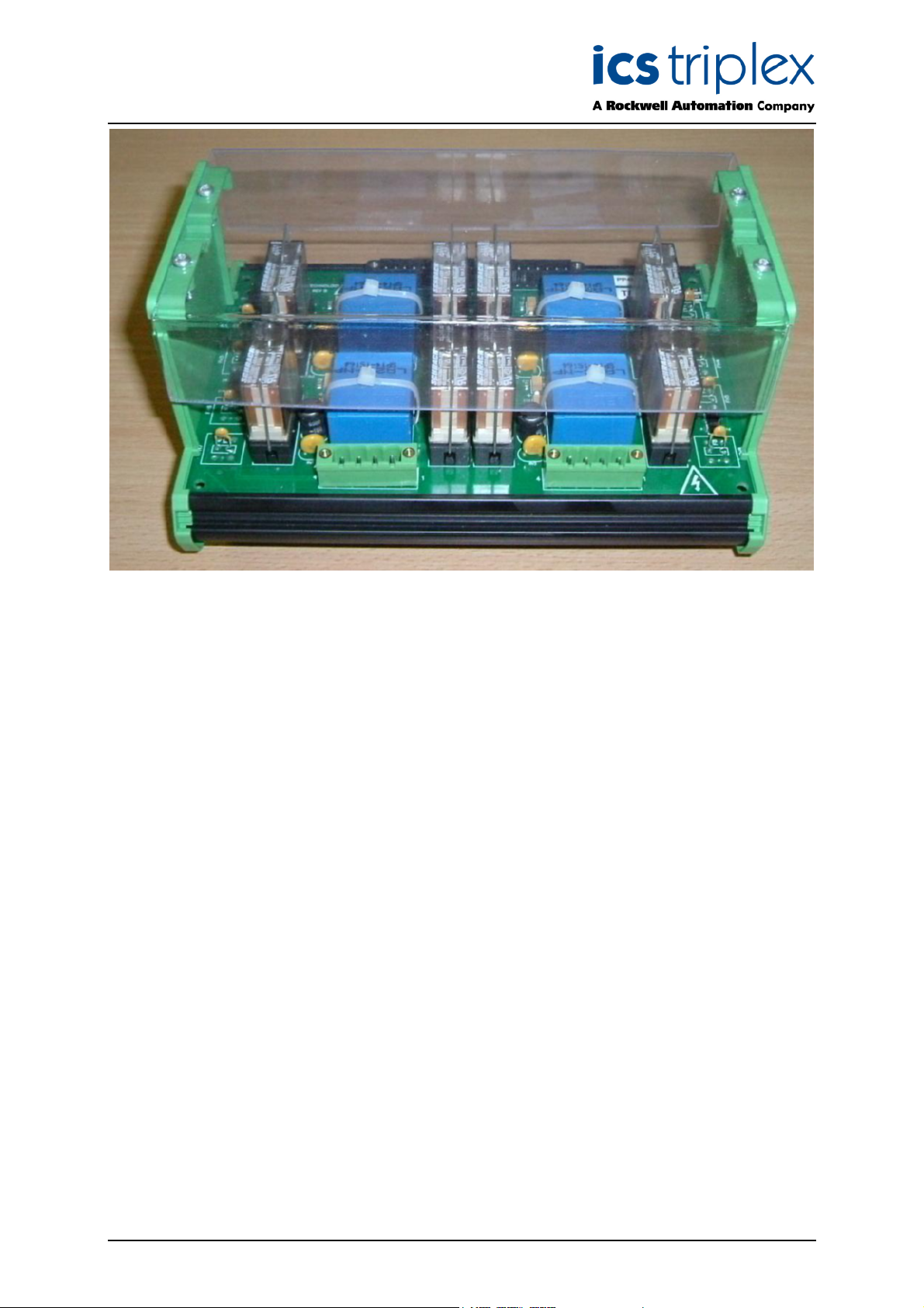
Figure 1 Module Photograph
Issue 2 Mar 07 PD-T8891 3
Page 4

Trusted
TM
Speed Monitor OFTA T8891
Table of Contents
1. Product Range................................................................................................................................8
2. Assembly........................................................................................................................................9
3. External Interfaces .......................................................................................................................11
3.1. Speed Monitor Interface (SK1) .....................................................................................................11
3.2. Over-speed Trip - Field Output (SK2) ..........................................................................................12
3.3. Over-acceleration Trip - Field Output (SK3) .................................................................................12
4. Specifications ...............................................................................................................................13
4.1. Relay Coil Input Specifications .....................................................................................................13
4.2. Relay Contact Specifications........................................................................................................14
4.3. General Specifications .................................................................................................................15
5. Dimensions...................................................................................................................................16
6. Replaceable Component Location ...............................................................................................17
Issue 2 Mar 07 PD-T8891 4
Page 5

Trusted
TM
Speed Monitor OFTA T8891
Figures
Figure 1 Module Photograph ....................................................................................................................3
Figure 2 T8891 Overview .......................................................................................................................10
Figure 3 Relay Operating Range ............................................................................................................13
Figure 4 Relay Contact Maximum DC load breaking Capacity...............................................................14
Figure 6 Dimensions...............................................................................................................................16
Figure 7 Replaceable Component Location ...........................................................................................17
Tab l es
Table 1 T8442 TMR Speed Monitor Product Range ................................................................................8
Table 2 T8442 Interface Connector (SK1)..............................................................................................11
Table 3 Over-speed Trip Field Output Connector (SK2) ........................................................................12
Table 4 Over-acceleration Trip Field Output Connector (SK3)...............................................................12
Table 5 Relay Coil Input Specifications ..................................................................................................13
Table 6 Relay Contact Specifications .....................................................................................................14
Table 7 General Specifications...............................................................................................................15
Table 8 Replaceable Components .........................................................................................................18
Issue 2 Mar 07 PD-T8891 5
Page 6

Trusted
TM
Speed Monitor OFTA T8891
Notice
The content of this document is confidential to ICS Triplex Technology Ltd. companies and their
partners. It may not be given away, lent, resold, hired out or made available to a third party for any
purpose without the written consent of ICS Triplex Technology Ltd.
This document contains proprietary information that is protected by copyright. All rights are reserved.
icrosoft, Windows, Windows 95, Windows NT, Windows 2000, and Windows XP are registered
M
trademarks of Microsoft Corporation.
The information contained in this document is subject to change without notice. The reader should, in
all cases, consult ICS Triplex Technology Ltd. to determine whether any such changes have been
made. From time to time, amendments to this document will be made as necessary and will be
distributed by ICS Triplex Technology Ltd.
Information in this documentation set may be subject to change without notice and does not represent
a commitment on the part of ICS Triplex Technology Ltd..
The contents of this document, which may also include the loan of software tools, are subject to the
confidentiality and other clause(s) within the Integrator Agreement and Software License Agreement.
No part of this documentation may be reproduced or transmitted in any form or by any means,
electronic or mechanical, including photocopying and recording, for any purpose, without the express
written permission of ICS Triplex Technology Ltd.
Disclaimer
The illustrations, figures, charts, and layout examples in this manual are intended solely to illustrate the
text of this manual.
The user of, and those responsible for applying this equipment, must satisfy themselves as to the
acceptability of each application and use of this equipment.
This document is based on information available at the time of its publication. While efforts have been
made to be accurate, the information contained herein does not purport to cover all details or variations
in hardware or software, nor to provide for every possible contingency in connection with installation,
operation, or maintenance. Features may be described herein which are present in all hardware or
software systems. ICS Triplex Technology Ltd. assumes no obligation of notice to holders of this
document with respect to changes subsequently made.
ICS Triplex Technology Ltd. makes no representation or warranty, expressed, implied, or statutory with
respect to, and assumes no responsibility for the accuracy, completeness, sufficiency, or usefulness of
the information contained herein. No warranties of merchantability or fitness for purpose shall apply.
Issue 2 Mar 07 PD-T8891 6
Page 7

Trusted
TM
Speed Monitor OFTA T8891
Revision and Updating Policy
All new and revised information pertinent to this document shall be issued by ICS Triplex Technology
Ltd. and shall be incorporated into this document in accordance with the enclosed instructions. The
change is to be recorded on the Amendment Record of this document.
Precautionary Information
WARNING
Warning notices call attention to the use of materials, processes, methods, procedures or limits which
must be followed precisely to avoid personal injury or death.
CAUTION
Caution notices call attention to methods and procedures which must be followed to avoid damage to
the equipment.
Notes:
Notes highlight procedures and contain information to assist the user in the understanding of the
information contained in this document
Warning
RADIO FREQUENCY INTERFERENCE
Most electronic equipment is influenced by Radio Frequency Interference (RFI). Caution should be
exercised with regard to the use of portable communications equipment around such equipment.
Signs should be posted in the vicinity of the equipment cautioning against the use of portable
communications equipment.
MAINTENANCE
Maintenance must be performed only by qualified personnel, otherwise personal injury or death, or
damage to the system may be caused.
Caution
HANDLING
Under no circumstances should the module housing be removed.
Associated Documents
Product Descriptions (PD) provide product specific information.
The Safety Manual contains the recommended safety requirements for the safety system design.
The PD8082B – Toolset Suite provides specific guidance on system configuration and application
generation.
The Operator and Maintenance Manual contains general guidelines on maintenance and diagnostic
procedures.
For technical support email: support@icstriplex.com
Issue 2 Mar 07 PD-T8891 7
Page 8

Trusted
TM
Speed Monitor OFTA T8891
1. Product Range
Catalogue No. Product name Description
T8442 TMR Speed
Monitor.
T8846 Speed Input FTA
(SIFTA)
T8891 Speed Output FTA
(SOFTA)
TC-801 I/O Companion
Slot, Speed Monitor
to FTA (Internal )
Table 1 T8442 TMR Speed Monitor Product Range
Trusted TMR Speed Monitor Module.
Input field termination assembly for use with the
T8442 TMR Speed Monitor.
Output field termination assembly for use with the
T8442 TMR Speed Monitor.
Companion Slot I/O cable with internal power,
connects the T8442 to a single SIFTA and up to
three SOFTAs.
Issue 2 Mar 07 PD-T8891 8
Page 9

Trusted
TM
Speed Monitor OFTA T8891
2. Assembly
A single Trusted T8442 TMR Speed Monitor interfaces with three T8891 SOFTA assemblies.
A single SOFTA assembly provides the relay switching elements for one over-speed output and one
over-acceleration output.
For each output channel, an isolated Hall Effect current sensor is connected in series with each of the
two parallel contact switching paths. The outputs from these sensors connect to the T8442 via the
TC801 field interface cable and are used for relay contact diagnostic and fault detection purposes.
Force guided contact, safety relays are used on the SOFTA assembly. The physical properties of these
relays ensure that welded primary contacts can be detected by monitoring the auxiliary contact status
signal. The contact status signal is passed back to the T8442 via the TC801 field interface cable for
diagnostic and fault detection purposes.
The output contact can be used as a normally-open (de-energised relay) or a normally-closed (deenergised relay) contact for connection to the field load. They are electrically isolated from all other
signals on the T8891 SOFTA and T8442 Speed Monitor.
For critical shutdown applications only the normally-open contacts should be used.
Power, relay drive, current sense and contact status signals all interface directly to the T8442 via the
TC801 field interface cable.
Issue 2 Mar 07 PD-T8891 9
Page 10

Trusted
TM
Speed Monitor OFTA T8891
ver-Speed Trip Contact N/O
O
ver-Speed Trip Contact N/C
O
Over-Speed Trip Contact N/C
Over-Speed Trip Contact N/O
Over-Acceleration Trip Contact N/O
Over-Acceleration Trip Contact N/C
Over-Acceleration Trip Contact N/C
Over-Acceleration Trip Contact N/O
SK2/3
S
K2/1
SK2/2
SK2/4
SK3/3
SK3/1
SK3/2
SK3/4
D1/1
H
Current
S
ensor
SENSE1 SENSE 3
HD2/1
HD3/1
Current
Sensor
HD4/1
SENSE1 +VE
SENSE2 +VE
SENSE3 +VE
SENSE4 +VE
SENSE1 -VE
S
ENSE2 -VE
SENSE3 -VE
ENSE4 -VE
S
D5/1
H
Current
S
ensor
HD6/1
HD7/1
Current
Sensor
HD8/1
SK1/17
F3
F4
F7
F
8
F2
F
1
F6
F5
D5/2
H
HD1/2
HD2/2
HD6/2
HD7/2
D3/2
H
SENSE4SENSE2
D4/2
H
D8/2
H
SK1/16
SK1/1
SK1/2
SK1/7
SK1/20
SK1/4
H
D
5
SK1/9
H
D
6
SK1/3
HD
1
SK1/8
HD
2
SK1/14
Spare
SK1/6
SK1/5
SK1/11
HD
7
SK1/13
HD
8
SK1/10
HD
3
SK1/12
HD
4
SK1/15
SK1/19
SK1/18
15V dc (1)
+
+15V dc (2)
-15V dc (1)
-15V dc (2)
0V Return
V Return
0
Over-Speed Trip
Relay Drive A
Over-Speed Trip
Relay Drive B
Over-Speed Trip
elay Drive C
R
Over-Speed Trip
Relay Drive D
Over-Speed Channel
Load Current Feedback (1)
ver-Speed Channel
O
Load Current Feedback (2)
Over-Acceleration Trip
Relay Drive A
Over-Acceleration Trip
Relay Drive B
Over-Acceleration Trip
Relay Drive C
Over-AccelerationTrip
Relay Drive D
Contact Status
Feedback
Over-Acceleration Channel
Load Current Feedback (1)
Over-Acceleration Channel
Load Current Feedback (2)
Figure 2 T8891 Overview
Issue 2 Mar 07 PD-T8891 10
Page 11

Trusted
TM
Speed Monitor OFTA T8891
3. External Interfaces
The three external interfaces to the T8891 SOFTA are described in this section.
3.1. Speed Monitor Interface (SK1)
This provides the interface to the Trusted T8442 Speed Monitor. The connector mates directly with the
Trusted TC-801 cable assembly.
Pin Signal Name Description
1 VFIELD_M15_1 -15V dc Power Supply Input (1)
2 VFIELD_M15_2 -15V dc Power Supply Input (2)
3 OVERSPEED_COIL_C Over-speed Relay Coil Input (C)
4 OVERSPEED_COIL_A Over-speed Relay Coil Input (A)
5 OVERSPEED_ISENSE_2 Over-speed Load Current Sensor Output (2)
6 OVERSPEED_ISENSE_1 Over-speed Load Current Sensor Output (1)
7 0V 0V Power Supply Input
8 OVERSPEED_COIL_D Over-speed Relay Coil Input (D)
9 OVERSPEED_COIL_B Over-speed Relay Coil Input (B)
10 OVERACCELERATION_COIL_C Over-acceleration Relay Coil Input (C)
11 OVERACCELERATION_COIL_A Over-acceleration Relay Coil Input (A)
12 OVERACCELERATION_COIL_D Over-acceleration Relay Coil Input (D)
13 OVERACCELERATION_COIL_B Over-acceleration Relay Coil Input (B)
14 NOT CONNECTED Spare
15 CONTACT_STATUS Contact Status Output
16 VFIELD_P15_2 +15V dc Power Supply Input (2)
17 VFIELD_P15_1 +15V dc Power Supply Input (1)
18 OVERACCELERATION_ISENSE_2 Over-acceleration Load Current Sensor Output (2)
19 OVERACCELERATION_ISENSE_1 Over-acceleration Load Current Sensor Output (1)
20 0V 0V Power Supply Input
Table 2 T8442 Interface Connector (SK1)
Issue 2 Mar 07 PD-T8891 11
Page 12

Trusted
TM
Speed Monitor OFTA T8891
3.2. Over-speed Trip - Field Output (SK2)
This connector provides the volt free contact field connections for the over-speed trip output.
NOTE: Over-current protection for the field load must be provided externally.
Pin Signal Name Description
1 Over-speed Normally Closed Contact A
2 Over-speed Normally Closed Contact B
3 Over-speed Normally Open Contact A
4 Over-speed Normally Open Contact B
Over-speed trip output.
Normally closed contacts (shutdown state)
Over-speed trip output.
Normally open contacts (shutdown state)
Table 3 Over-speed Trip Field Output Connector (SK2)
3.3. Over-acceleration Trip - Field Output (SK3)
This connector provides the volt free contact field connections for the over-acceleration trip output.
NOTE: Over-current protection for the field load must be provided externally.
Pin Signal Name Description
1 Over-acceleration Normally Closed Contact A
2 Over-acceleration Normally Closed Contact B
3 Over-acceleration Normally Open Contact A
4 Over-acceleration Normally Open Contact B
Over-acceleration trip output.
Normally closed contacts (shutdown state)
Over-acceleration trip output.
Normally open contacts (shutdown state)
Table 4 Over-acceleration Trip Field Output Connector (SK3)
Issue 2 Mar 07 PD-T8891 12
Page 13

Trusted
TM
Speed Monitor OFTA T8891
4. Specifications
4.1. Relay Coil Input Specifications
Parameter Min. Typ. Max. Unit Note
Nominal Voltage 24 Vdc
Pull-in Voltage 18 Vdc
Release Voltage 2.4 Vdc
Coil resistance 740 906 G
Coil current 29.2 mA Coil voltage 24Vdc
Nominal coil power 700 mW
Table 5 Relay Coil Input Specifications
Figure 3 Relay Operating Range
Issue 2 Mar 07 PD-T8891 13
Page 14
Trusted
TM
Speed Monitor OFTA T8891
4.2. Relay Contact Specifications
Parameter Min. Typ. Max. Unit Note
Rated current 3 A
Rated voltage 150 Vac
Maximum breaking voltage AC 440 Vac
Maximum breaking capacity AC 1500 VA
Contact resistance
100
2
Table 6 Relay Contact Specifications
mGG24Vdc 1A
5Vdc 10mA
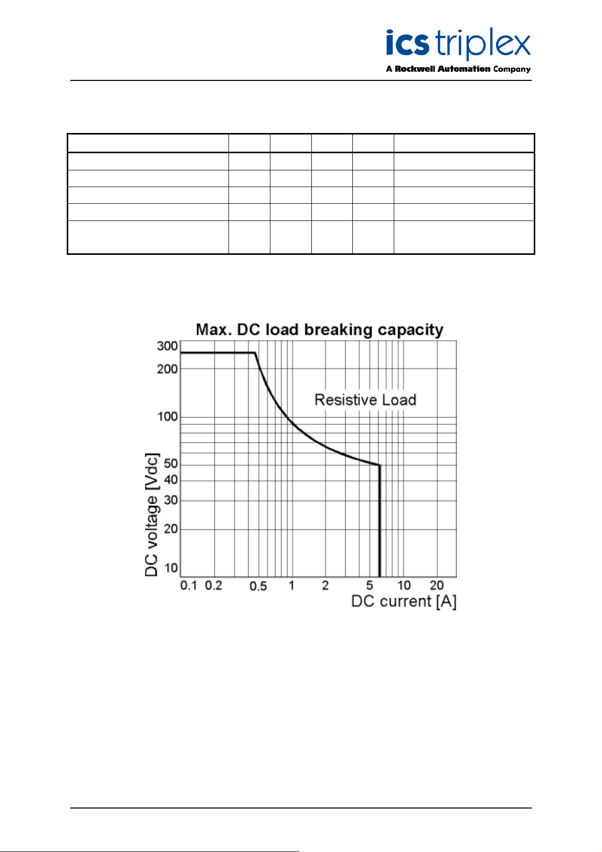
Figure 4 Relay Contact Maximum DC load breaking Capacity
Issue 2 Mar 07 PD-T8891 14
Page 15

Trusted
TM
Speed Monitor OFTA T8891
4.3. General Specifications
Parameter Min Typ Max Unit Note
Field Common Isolation
Sustained working -250 250 V dc
Maximum withstanding -2500 2500 V dc
Temperature
Operating temperature -5 60
Storage temperature -25 70
Temperature change 0.5
Humidity
Operating humidity 5 95 %RH Non-Condensing
Dimensions
Height
Width
Depth
Weight
°C
°C
°C/min
102
(4.0)
180
(7.10)
127
(5.0)
0.55
(1.2)
Table 7 General Specifications
mm
(inches)
mm
(inches)
mm
(inches)
Kg
(lbs)
Issue 2 Mar 07 PD-T8891 15
Page 16

Trusted
TM
Speed Monitor OFTA T8891
5. Dimensions
180mm (7.10 inches)
1
SK2
SK1
1414
20
SK3
102mm (4 inches) 127mm (5 inches)
Figure 5 Dimensions
Issue 2 Mar 07 PD-T8891 16
Page 17
Trusted
TM
Speed Monitor OFTA T8891
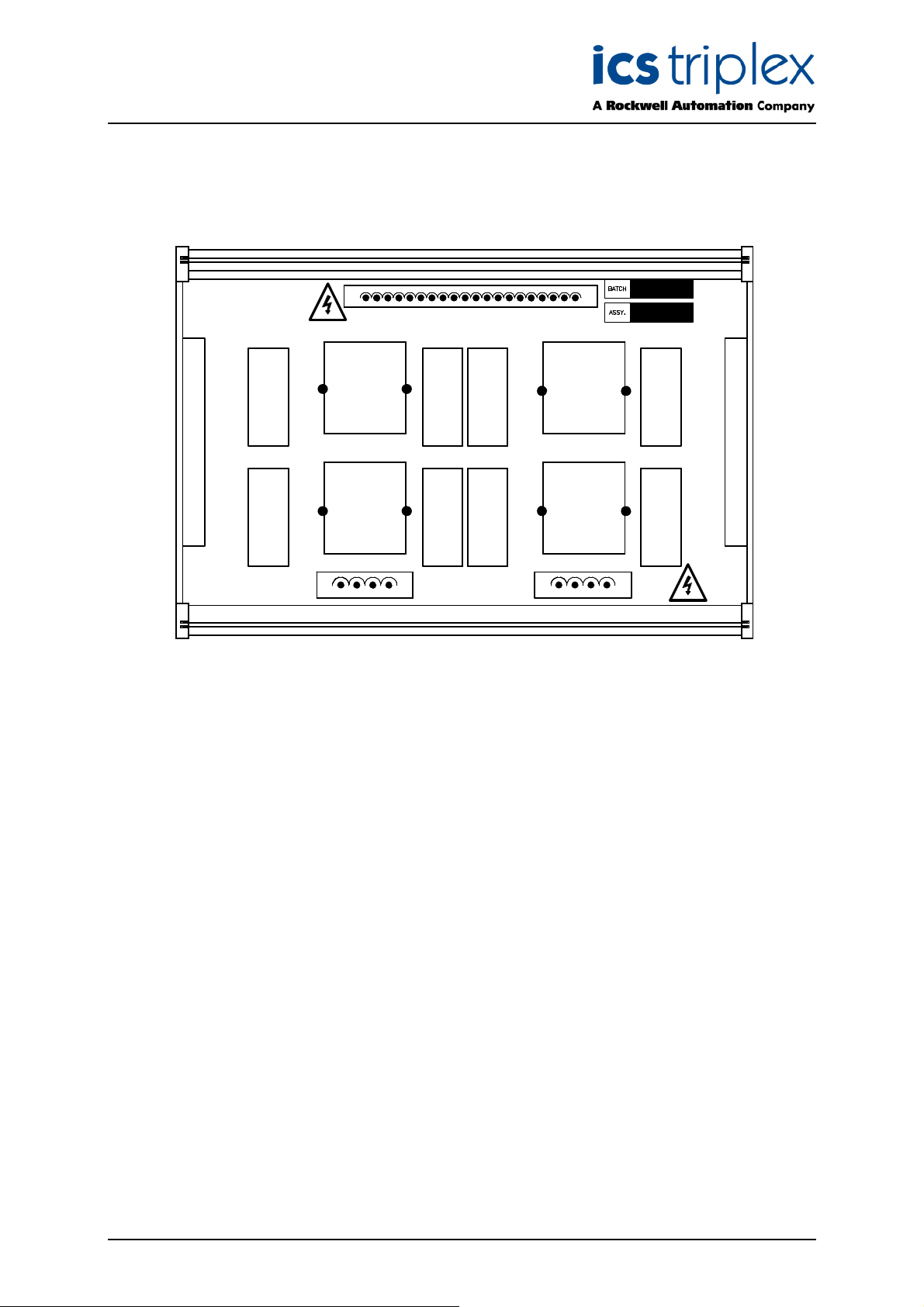
6. Replaceable Component Location
RELAY
HD1
RELAY
HD5
1
CURRENT
SENSOR
SENSE1
CURRENT
SENSOR
SENSE3
SK2
SK1
RELAY
RELAY
HD3
HD2
RELAY
RELAY
HD6
HD7
1414
20
CURRENT
SENSOR
SENSE2
CURRENT
SENSOR
SENSE4
SK3
Figure 6 Replaceable Component Location
RELAY
HD4
RELAY
HD8
Issue 2 Mar 07 PD-T8891 17
Page 18

Trusted
Component Ref Description Notes
Relay HD1 Over-speed relay Over-speed output leg 2 (A)
Relay HD2 Over-speed relay Over-speed output leg 2 (B)
Relay HD3 Over-acceleration relay Over-acceleration output leg 2 (A)
Relay HD4 Over-acceleration relay Over-acceleration output leg 2 (B)
Relay HD5 Over-speed relay Over-speed output leg 1 (A)
Relay HD6 Over-speed relay Over-speed output leg 1 (B)
Relay HD7 Over-acceleration relay Over-acceleration output leg 1 (A)
Relay HD8 Over-acceleration relay Over-acceleration output leg 1 (B)
Current sensor SENSE1 Load current sensor Over-speed output leg 2
Current sensor SENSE2 Load current sensor Over-acceleration output leg 2
Current sensor SENSE3 Load current sensor Over-speed output leg 1
Current sensor SENSE4 Load current sensor Over-acceleration output leg 2
TM
Speed Monitor OFTA T8891
Table 8 Replaceable Components
Issue 2 Mar 07 PD-T8891 18
Page 19

Trusted
TM
Speed Monitor OFTA T8891
This page is intentionally blank
Issue 2 Mar 07 PD-T8891 19
Page 20

 Loading...