

Page 1

TrustedTM
PD-T8846
TM
Trusted
Speed Monitor IFTA (SIFTA)
Introduction
M
T
The Trusted
provides the input field interface for three rotating machine groups when used as part of a Trusted
T8442 TMR Speed Monitor system.
Features
• Provides all necessary input interfaces for a Trusted T8442 TMR Speed Monitor.
• Nine speed input channels arranged as three groups of three inputs.
Speed Monitor Input Field Termination Assembly (SIFTA) is a DIN rail assembly. It
M
T
• Separate field power inputs for each of the three speed input groups.
• Field power and signal isolation between input groups.
• Versatile input connectivity allows interfacing with:
• Active speed sensors with Totem-Pole outputs.
• Active speed sensors with open-Collector outputs.
• Passive magnetic, inductive speed sensors.
• Standard DIN Rail mounting.
• All Fuses can be replaced in situ.
Issue 2 Apr 10 PD-T8846 1
Page 2

Trusted
Issue Record
Issue
Number Date Revised by Technical CheckAuthorised by Modification
1 Sept 05 J W Clark Format
2 Apr 10 S. Blackett A. Holgate P. Stock Corrections to
TM
Speed Monitor IFTA T8846
termination pin
numbers
Issue 2 Apr 10 PD-T8846 2
Page 3
Trusted
TM
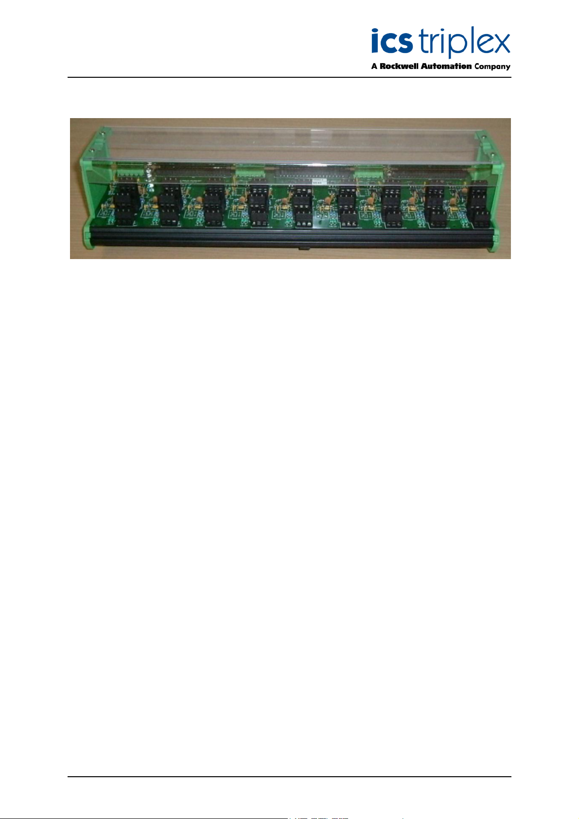
Speed Monitor IFTA T8846
Figure 1 T8846 Module Photo
Issue 2 Apr 10 PD-T8846 3
Page 4

Trusted
TM
Speed Monitor IFTA T8846
Table of Contents
1. Product Range ...............................................................................................................................8
2. Assembly........................................................................................................................................9
3. External Interfaces .......................................................................................................................10
.1.
3
3.2. Speed Monitor Interfaces .............................................................................................................12
3.3. Speed Inputs ................................................................................................................................15
4. Field Connection Arrangements...................................................................................................18
4.1. Active Totem Pole Output Sensor Types .....................................................................................18
4.1.1. Sensor Power Derived from FTA .................................................................................................18
4.1.2. Sensor Power Derived Externally ................................................................................................19
4.2. Active Open Collector Output Sensor Types ...............................................................................20
4.2.1. Sensor Power Derived From FTA ................................................................................................20
4.2.2. Sensor Power Derived Externally ................................................................................................21
ield Power Inputs........................................................................................................................11
F
4.3. Passive Output Sensor Types......................................................................................................22
4.4. Chassis Ground Connections ......................................................................................................23
5. Specifications ...............................................................................................................................24
5.1. Group VField Power Supply Input Specifications ........................................................................24
5.2. Group Speed Input Specifications................................................................................................24
5.3. General Specifications .................................................................................................................25
Issue 2 Apr 10 PD-T8846 4
Page 5

Trusted
TM
Speed Monitor IFTA T8846
Figures
Figure 1 T8846 Module Photo..................................................................................................................3
Figure 2 T8846 Speed Input Channel Overview ......................................................................................9
Figure 3 T8846 General Assembly – Top view and Front view .............................................................10
igure 4 Active Totem Pole Output Sensor Connections (FTA Derived Field Supply) ..........................18
F
Figure 5 Active Totem Pole Output Sensor (Externally Derived Field Supply) ......................................19
Figure 6 Active Open Collector Output Sensor (FTA Derived Field Supply) .........................................20
Figure 7 Active Open Collector Output (Externally Derived Field Supply).............................................21
Figure 8 Passive Output Sensor Connections .......................................................................................22
Figure 9 Chassis Ground Connections ..................................................................................................23
Tables
Table 1 T8442 TMR Speed Monitor Product Range ................................................................................8
Table 2 - Field Power Input Connections ...............................................................................................11
Table 3 Speed Monitor Interface Group 1 ..............................................................................................12
Table 4 Speed Monitor Interface Group 2 ..............................................................................................13
Table 5 Speed Monitor Interface Group 3 ..............................................................................................14
Table 6 Speed Input Connections ..........................................................................................................17
Table 7 Group VField Power Supply Input Specifications......................................................................24
Table 8 Group Speed Input Specifications.............................................................................................24
Table 9 General Specifications ..............................................................................................................25
Issue 2 Apr 10 PD-T8846 5
Page 6

Trusted
TM
Speed Monitor IFTA T8846
Notice
The content of this document is confidential to ICS Triplex Technology Ltd. companies and their
partners. It may not be given away, lent, resold, hired out or made available to a third party for any
purpose without the written consent of ICS Triplex Technology Ltd.
This document contains proprietary information that is protected by copyright. All rights are reserved.
Microsoft, Windows, Windows 95, Windows NT, Windows 2000, and Windows XP are registered
trademarks of Microsoft Corporation.
The information contained in this document is subject to change without notice. The reader should, in
all cases, consult ICS Triplex Technology Ltd. to determine whether any such changes have been
made. From time to time, amendments to this document will be made as necessary and will be
distributed by ICS Triplex Technology Ltd.
Information in this documentation set may be subject to change without notice and does not represent
a commitment on the part of ICS Triplex Technology Ltd..
The contents of this document, which may also include the loan of software tools, are subject to the
confidentiality and other clause(s) within the Integrator Agreement and Software License Agreement.
No part of this documentation may be reproduced or transmitted in any form or by any means,
electronic or mechanical, including photocopying and recording, for any purpose, without the express
written permission of ICS Triplex Technology Ltd.
Disclaimer
The illustrations, figures, charts, and layout examples in this manual are intended solely to illustrate
the text of this manual.
The user of, and those responsible for applying this equipment, must satisfy themselves as to the
acceptability of each application and use of this equipment.
This document is based on information available at the time of its publication. While efforts have been
made to be accurate, the information contained herein does not purport to cover all details or
variations in hardware or software, nor to provide for every possible contingency in connection with
installation, operation, or maintenance. Features may be described herein which are present in all
hardware or software systems. ICS Triplex Technology Ltd. assumes no obligation of notice to holders
of this document with respect to changes subsequently made.
ICS Triplex Technology Ltd. makes no representation or warranty, expressed, implied, or statutory
with respect to, and assumes no responsibility for the accuracy, completeness, sufficiency, or
usefulness of the information contained herein. No warranties of merchantability or fitness for purpose
shall apply.
Issue 2 Apr 10 PD-T8846 6
Page 7

Trusted
TM
Speed Monitor IFTA T8846
Revision and Updating Policy
All new and revised information pertinent to this document shall be issued by ICS Triplex Technology
Ltd. and shall be incorporated into this document in accordance with the enclosed instructions. The
change is to be recorded on the Amendment Record of this document.
Precautionary Information
WARNING
Warning notices call attention to the use of materials, processes, methods, procedures or limits which
must be followed precisely to avoid personal injury or death.
CAUTION
Caution notices call attention to methods and procedures which must be followed to avoid damage to
the equipment.
Notes:
Notes highlight procedures and contain information to assist the user in the understanding of the
information contained in this document
Warning
RADIO FREQUENCY INTERFERENCE
Most electronic equipment is influenced by Radio Frequency Interference (RFI). Caution should be
exercised with regard to the use of portable communications equipment around such equipment.
Signs should be posted in the vicinity of the equipment cautioning against the use of portable
communications equipment.
MAINTENANCE
Maintenance must be performed only by qualified personnel, otherwise personal injury or death, or
damage to the system may be caused.
Caution
HANDLING
Under no circumstances should the module housing be removed.
Associated Documents
Product Descriptions (PD) provide product specific information.
The Safety Manual contains the recommended safety requirements for the safety system design.
The PD8082B – Toolset Suite provides specific guidance on system configuration and application
generation.
The Operator and Maintenance Manual contains general guidelines on maintenance and diagnostic
procedures.
For technical support email: support@icstriplex.com
Issue 2 Apr 10 PD-T8846 7
Page 8

Trusted
TM
Speed Monitor IFTA T8846
1. Product Range
Catalogue No. Product name Description
T8442 TMR Speed
Monitor.
T8846 Speed Input FTA
(SIFTA)
T8891 Speed Output FTA
(SOFTA)
TC-801 I/O Companion
Slot, Speed Monitor
to FTA (Internal )
Table 1 T8442 TMR Speed Monitor Product Range
Trusted TMR Speed Monitor Module.
Input field termination assembly for use with the
T8442 TMR Speed Monitor.
Output field termination assembly for use with the
T8442 TMR Speed Monitor.
Companion Slot I/O cable with internal power. This
connects an active/standby hotswap pair of T8442
modules to a single SIFTA and up to three SOFTAs.
Issue 2 Apr 10 PD-T8846 8
Page 9

Trusted
TM
Speed Monitor IFTA T8846
2. Assembly
he T8846 Speed Input Field Termination Assembly (SIFTA) is an integral part of the overall T8442
T
Speed monitor system. It is DIN rail mounted, containing passive signal conditioning, power
distribution and protection components.
Each T8442 Speed Monitor Module hot swap pair requires a single T8846 SIFTA when installed in a
Trusted
The SIFTA has nine identical speed transducer signal conditioning circuits arranged as three groups
of three.
Each of the three groups is a galvanically isolated entity, with its own field power and I/O signal
interfaces.
Multiple sensors must be employed for SIL3 applications.
TM
system.
Figure 2 T8846 Speed Input Channel Overview
Issue 2 Apr 10 PD-T8846 9
Page 10

Trusted
TM
Speed Monitor IFTA T8846
3. External Interfaces
igure 3 shows the T8846 general assembly.
F
Figure 3 T8846 General Assembly – Top view and Front view
Issue 2 Apr 10 PD-T8846 10
Page 11

Trusted
TM
Speed Monitor IFTA T8846
3.1. Field Power Inputs
This section details the field power input connections for each speed monitor input group.
There are three 4 way connectors on the FTA which provide the field power interface to the FTA. Each
connector is dedicated to one speed input group.
Refer to Figure 3 for the location of the interface sockets
Interface Pin Signal Name Description
SK1 A1 Group 1 Vfield A Input +24Vdc (A) Dual redundant power supply input for group 1 speed
inputs.
SK1 A2 Group 1 Vfield Return
Input
SK1 A3 Group 1 Vfield Return
Input
SK1 B1 Group 1 Vfield B Input +24Vdc (B) Dual redundant power supply input for group 1 speed
SK3 A1 Group 2 Vfield A Input +24Vdc (A) Dual redundant power supply input for group 2 speed
SK3 A2 Group 2 Vfield Return
Input
SK3 A3 Group 2 Vfield Return
Input
SK3 B1 Group 2 Vfield B Input +24Vdc (B) Dual redundant power supply input for group 2 speed
0V Vfield Power supply return for group 1 speed inputs.
inputs.
inputs.
0V Vfield Power supply return for group 2 speed inputs.
inputs.
SK5 A1 Group 3 Vfield A Input +24Vdc (A) Dual redundant power supply input for group 3 speed
inputs.
SK5 A2 Group 3 Vfield Return
Input
SK5 A3 Group 3 Vfield Return
Input
SK5 B1 Group 3 Vfield B Input +24Vdc (B) Dual redundant power supply input for group 3 speed
0V Vfield Power supply return for group 3 speed inputs.
inputs.
Table 2 - Field Power Input Connections
Issue 2 Apr 10 PD-T8846 11
Page 12

Trusted
TM
Speed Monitor IFTA T8846
3.2. Speed Monitor Interfaces
This section details the interfaces between the T8846 SIFTA and the Trusted T8442 Speed Monitor.
There are three 20 way connectors on the FTA which provide the interface to the Trusted T8442
Speed Monitor. Each connector is dedicated to one speed input group and mates directly with the
Trusted TC-801 cable assembly.
Refer to Figure 3 for the location of the connectors.
Interface Pin Description
SK2 1 Group 1 VField (A) fused output
SK2 2 Group 1 VField (B) fused output
SK2 3 Not Connected
SK2 4 Group 1 Channel 1 MID Bias
SK2 5 Group 1 Channel 1 Passive (A) output
SK2 6 Group 1 0V (ground)
SK2 7 Group 1 Channel 1 Passive (B) output
SK2 8 Chassis Ground
SK2 9 Not Connected
SK2 10 Group 1 Channel 2 MID Bias
SK2 11 Group 1 Channel 2 Passive (A) output
SK2 12 Group 1 0V (ground)
SK2 13 Group 1 Channel 2 Passive (B) output
SK2 14 Chassis Ground
SK2 15 Not Connected
SK2 16 Group 1 Channel 3 MID Bias
SK2 17 Group 1 Channel 3 Passive (A) output
SK2 18 Group 1 0V (ground)
SK2 19 Group 1 Channel 3 Passive (B) output
SK2 20 Chassis Ground
Table 3 Speed Monitor Interface Group 1
Issue 2 Apr 10 PD-T8846 12
Page 13

Trusted
Interface Pin Description
SK4 1 Group 2 VField (A) fused output
SK4 2 Group 2 VField (B) fused output
SK4 3 Not Connected
SK4 4 Group 2 Channel 1 MID Bias
SK4 5 Group 2 Channel 1 Passive (A) output
SK4 6 Group 2 0V (ground)
SK4 7 Group 2 Channel 1 Passive (B) output
SK4 8 Chassis Ground
SK4 9 Not Connected
SK4 10 Group 2 Channel 2 MID Bias
SK4 11 Group 2 Channel 2 Passive (A) output
SK4 12 Group 2 0V (ground)
SK4 13 Group 2 Channel 2 Passive (B) output
SK4 14 Chassis Ground
SK4 15 Not Connected
SK4 16 Group 2 Channel 3 MID Bias
SK4 17 Group 2 Channel 3 Passive (A) output
SK4 18 Group 2 0V (ground)
SK4 19 Group 2 Channel 3 Passive (B) output
SK4 20 Chassis Ground
TM
Speed Monitor IFTA T8846
Table 4 Speed Monitor Interface Group 2
Issue 2 Apr 10 PD-T8846 13
Page 14

Trusted
Interface Pin Description
SK6 1 Group 3 VField (A) fused output
SK6 2 Group 3 VField (B) fused output
SK6 3 Not Connected
SK6 4 Group 3 Channel 1 MID Bias
SK6 5 Group 3 Channel 1 Passive (A) output
SK6 6 Group 3 0V (ground)
SK6 7 Group 3 Channel 1 Passive (B) output
SK6 8 Chassis Ground
SK6 9 Not Connected
SK6 10 Group 3 Channel 2 MID Bias
SK6 11 Group 3 Channel 2 Passive (A) output
SK6 12 Group 3 0V (ground)
SK6 13 Group 3 Channel 2 Passive (B) output
SK6 14 Chassis Ground
SK6 15 Not Connected
SK6 16 Group 3 Channel 3 MID Bias
SK6 17 Group 3 Channel 3 Passive (A) output
SK6 18 Group 3 0V (ground)
SK6 19 Group 3 Channel 3 Passive (B) output
SK6 20 Chassis Ground
TM
Speed Monitor IFTA T8846
Table 5 Speed Monitor Interface Group 3
Issue 2 Apr 10 PD-T8846 14
Page 15

Trusted
TM
Speed Monitor IFTA T8846
3.3. Speed Inputs
This section details the speed input terminal connections. These terminals are used to interface to the
field sensor input cables.
Refer to Figure 3 for the location of the interface terminals.
Interface Terminal Description
SK7 A1 Group 1 Channel 1 Fused VField Output
SK7 A2 Group 1 Channel 1 Open Collector Input
SK7 A3 Group 1 0V (Ground)
SK7 B1 Group 1 Channel 1 Open Collector Loopback
SK7 B2 Group 1 Channel 1 Passive A Input (A duplicate input is also available on SK7
terminal 7)
SK7 B3 Chassis Ground
SK7 C1 Group 1 Channel 1 Passive A Input (A duplicate of SK7 terminal 5)
SK7 C2 Group 1 Channel 1 Passive B Input
SK7 C3 Group 1 Channel 1 Active Bias Output
SK8 A1 Group 1 Channel 2 Fused Vfield Output
SK8 A2 Group 1 Channel 2 Open Collector Input
SK8 A3 Group 1 0V (Ground)
SK8 B1 Group 1 Channel 2 Open Collector Loopback
SK8 B2 Group 1 Channel 2 Passive A Input (A duplicate input is also available on SK8
terminal 7)
SK8 B3 Chassis Ground
SK8 C1 Group 1 Channel 2 Passive A Input (A duplicate of SK8 terminal 5)
SK8 C2 Group 1 Channel 2 Passive B Input
SK8 C3 Group 1 Channel 2 Active Input Bias
SK9 A1 Group 1 Channel 3 Fused Vfield Output
SK9 A2 Group 1 Channel 3 Open Collector Input
SK9 A3 Group 1 0V (Ground)
SK9 B1 Group 1 Channel 3 Open Collector Loopback
SK9 B2 Group 1 Channel 3 Passive A Input (A duplicate input is also available on SK9
terminal 7)
SK9 B3 Chassis Ground
SK9 C1 Group 1 Channel 3 Passive A Input (A duplicate of SK9 terminal 5)
SK9 C2 Group 1 Channel 3 Passive B Input
SK9 C3 Group 1 Channel 3 Active Input Bias
SK10 A1 Group 2 Channel 1 Fused Vfield Output
SK10 A2 Group 2 Channel 1 Open Collector Input
SK10 A3 Group 2 0V (Ground)
SK10 B1 Group 2 Channel 1 Open Collector Loopback
Issue 2 Apr 10 PD-T8846 15
Page 16

Trusted
Interface Terminal Description
SK10 B2 Group 2 Channel 1 Passive A Input (A duplicate input is also available on SK10
SK10 B3 Chassis Ground
SK10 C1 Group 2 Channel 1 Passive A Input (A duplicate of SK10 terminal 5)
SK10 C2 Group 2 Channel 1 Passive B Input
SK10 C3 Group 2 Channel 1 Active Input Bias
SK11 A1 Group 2 Channel 2 Fused Vfield Output
SK11 A2 Group 2 Channel 2 Open Collector Input
SK11 A3 Group 2 0V (Ground)
SK11 B1 Group 2 Channel 2 Open Collector Loopback
SK11 B2 Group 2 Channel 2 Passive A Input (A duplicate input is also available on SK11
SK11 B3 Chassis Ground
SK11 C1 Group 2 Channel 2 Passive A Input (A duplicate of SK11 terminal 5)
SK11 C2 Group 2 Channel 2 Passive B Input
SK11 C3 Group 2 Channel 2 Active Input Bias
TM
Speed Monitor IFTA T8846
terminal 7)
terminal 7)
SK12 A1 Group 2 Channel 3 Fused Vfield Output
SK12 A2 Group 2 Channel 3 Open Collector Input
SK12 A3 Group 2 0V (Ground)
SK12 B1 Group 2 Channel 3 Open Collector Loopback
SK12 B2 Group 2 Channel 3 Passive A Input (A duplicate input is also available on SK12
terminal 7)
SK12 B3 Chassis Ground
SK12 C1 Group 2 Channel 3 Passive A Input (A duplicate of SK12 terminal 5)
SK12 C2 Group 2 Channel 3 Passive B Input
SK12 C3 Group 2 Channel 3 Active Input Bias
SK13 A1 Group 3 Channel 1 Fused Vfield Output
SK13 A2 Group 3 Channel 1 Open Collector Input
SK13 A3 Group 3 0V (Ground)
SK13 B1 Group 3 Channel 1 Open Collector Loopback
SK13 B2 Group 3 Channel 1 Passive A Input (A duplicate input is also available on SK13
terminal 7)
SK13 B3 Chassis Ground
SK13 C1 Group 3 Channel 1 Passive A Input (A duplicate of SK13 terminal 5)
SK13 C2 Group 3 Channel 1 Passive B Input
SK13 C3 Group 3 Channel 1 Active Input Bias
SK14 A1 Group 3 Channel 2 Fused Vfield Output
SK14 A2 Group 3 Channel 2 Open Collector Input
SK14 A3 Group 3 0V (Ground)
SK14 B1 Group 3 Channel 2 Open Collector Loopback
Issue 2 Apr 10 PD-T8846 16
Page 17

Trusted
Interface Terminal Description
SK14 B2 Group 3 Channel 2 Passive A Input (A duplicate input is also available on SK14
SK14 B3 Chassis Ground
SK14 C1 Group 3 Channel 2 Passive A Input (A duplicate of SK14 terminal 5)
SK14 C2 Group 3 Channel 2 Passive B Input
SK14 C3 Group 3 Channel 2 Active Input Bias
SK15 A1 Group 3 Channel 3 Fused Vfield Output
SK15 A2 Group 3 Channel 3 Open Collector Input
SK15 A3 Group 3 0V (Ground)
SK15 B1 Group 3 Channel 3 Open Collector Loopback
SK15 B2 Group 3 Channel 3 Passive A Input (A duplicate input is also available on SK15
SK15 B3 Chassis Ground
SK15 C1 Group 3 Channel 3 Passive A Input (A duplicate of SK15 terminal 5)
SK15 C2 Group 3 Channel 3 Passive B Input
SK15 C3 Group 3 Channel 3 Active Input Bias
TM
Speed Monitor IFTA T8846
terminal 7)
terminal 7)
Table 6 Speed Input Connections
Issue 2 Apr 10 PD-T8846 17
Page 18

Trusted
TM
Speed Monitor IFTA T8846
4. Field Connection Arrangements
his section shows the speed input connection arrangements for typical sensor configurations.
T
Active sensors are considered as field powered devices, and are available in two principal varieties:
• Totem Pole output sensors, actively drive their outputs to a positive potential and to ground
and do not rely on an external voltage bias.
• Open Collector output sensors, can only actively drive their outputs to ground and rely on an
external pull-up resistor to bias the output to a positive potential. The T8846 SIFTA provides
the biasing components for this type of sensor.
Passive sensors are considered to be magnetic, inductive pick up devices with no field power
requirements.
4.1. Active Totem Pole Output Sensor Types
4.1.1. Sensor Power Derived from FTA
Figure 4 shows a typical field connection scheme for +24Vdc field powered speed sensors with totem
pole outputs. This arrangement uses the fused field supply derived from the FTA.
Figure 4 Active Totem Pole Output Sensor Connections (FTA Derived Field Supply)
Issue 2 Apr 10 PD-T8846 18
Page 19

Trusted
TM
Speed Monitor IFTA T8846
4.1.2. Sensor Power Derived Externally
Figure 5 shows a typical field connection scheme for field powered speed sensors with totem pole
outputs. This arrangement uses an external fused field supply.
Figure 5 Active Totem Pole Output Sensor (Externally Derived Field Supply)
Issue 2 Apr 10 PD-T8846 19
Page 20

Trusted
TM
Speed Monitor IFTA T8846
4.2. Active Open Collector Output Sensor Types
4.2.1. Sensor Power Derived From FTA
igure 6 shows a typical field connection scheme for +24Vdc field powered speed sensors with open
F
collector outputs. This arrangement uses the fused field supply derived from the FTA.
Figure 6 Active Open Collector Output Sensor (FTA Derived Field Supply)
Issue 2 Apr 10 PD-T8846 20
Page 21

Trusted
TM
Speed Monitor IFTA T8846
4.2.2. Sensor Power Derived Externally
Figure 7 shows a typical connection scheme for field powered speed sensors with open collector
outputs. This arrangement uses an external fused field supply.
Figure 7 Active Open Collector Output (Externally Derived Field Supply)
Issue 2 Apr 10 PD-T8846 21
Page 22

Trusted
TM
Speed Monitor IFTA T8846
4.3. Passive Output Sensor Types
Figure 8 shows a typical field connection scheme for passive inductive pick-up speed sensors.
SENSOR
SIGNAL OUT (A)
SIGNAL OUT (B)
N/C
N/C
N/C
N/C
N/C
SCREEN
N/C
A1
A2
A3
B1
B2
B3
C1
C2
C3
Figure 8 Passive Output Sensor Connections
Issue 2 Apr 10 PD-T8846 22
Page 23

Trusted
TM
Speed Monitor IFTA T8846
4.4. Chassis Ground Connections
The chassis ground plane on the T8846 is common across all groups of speed inputs and Speed
Monitor interface connections.
The screening shield of each speed input signal cable should be connected to chassis ground at the
T8846 assembly.
Each speed input channel has a terminal to allow connection of the screening shield to chassis
ground, Refer to section 3.3 for connection details.
The T8846 chassis ground plane must be connected to a local chassis ground close to where the
assembly is mounted.
There are two studs provided on the assembly to allow this connection to be made. These are marked
as TERM1 & TERM2 on the PCB silkscreen legend.
Note : Only one connection should be made between the T8846 and local chassis ground.
Figure 9 Chassis Ground Connections
Issue 2 Apr 10 PD-T8846 23
Page 24

Trusted
TM
Speed Monitor IFTA T8846
5. Specifications
5.1. Group VField Power Supply Input Specifications
Parameter Min. Typ. Max. Unit Note
Group Vfield Input Voltage Range
VField (A) and VField (B) Inputs
Maximum Group VField Input Current
VField (A) and VField (B) Inputs
18 32 Vdc w.r.t. Group VField Return
1 A
Table 7 Group VField Power Supply Input Specifications
5.2. Group Speed Input Specifications
Parameter Min. Typ. Max. Unit Note
GROUP VFIELD OUTPUT
Group Vfield output voltage
@ 50mA load current
Maximum Group Vfield output current 62.5 mA
GROUP SPEED INPUTS
Open Collector Input
Pull-up resistance to Group Vfield.
Maximum Open Collector Input
Voltage
Open collector Input to
Open collector output resistance.
Active Input Bias Voltage output
w.r.t Group VField Return
22.6 Vdc VField input voltages @ 24Vdc
2000 Ohms
33 V w.r.t. Group VField Return
4990 Ohms
1.90 Vdc Group Vfield Input = 24Vdc
Differential input resistance
Passive (A) & Passive (B) Inputs
Maximum Differential Input Voltage
Passive (A) & Passive (B) Inputs
632 Ohms
10 V 632 ohm input resistance
Table 8 Group Speed Input Specifications
Issue 2 Apr 10 PD-T8846 24
Page 25

Trusted
TM
Speed Monitor IFTA T8846
5.3. General Specifications
Parameter Min Typ Max Unit Note
Temperature
Operating temperature -5 60
Storage temperature -25 70
Temperature change 0.5
Humidity
Operating humidity 5 95 %RH Non-Condensing
Dimensions
Height
Width
Depth
Weight
°C
°C
°C/min
102
(4.0)
391
(15.40)
127
(5.0)
0.75
(1.6)
Table 9 General Specifications
mm
(inches)
mm
(inches)
mm
(inches)
Kg
(lbs)
Refer to Figure 3
Issue 2 Apr 10 PD-T8846 25
Page 26

 Loading...