

Page 1

TrustedTM
PD-T8842
TM
Trusted
Versatile FTA
Introduction
The TrustedTM Versatile Field Termination Assembly (VFTA) T8842 is primarily designed to act as the
main interface between field devices associated with the detection and suppression of fire and gas
hazards, and the TrustedTM TMR Zone Interface Module T8448. It is also used as the interface for the
TrustedTM TMR Valve Monitor Module T8449, for which digital outputs to solenoid valves alternate with
valve position analogue inputs.
Each channel of the VFTA is configurable to enable a variety of field devices to be connected. These
include devices generating both analogue and digital input signals, and output devices requiring a
digital signal at up to 28V dc.
Features
40 channels per VFTA each configurable as inputs or outputs.
Industrial standard field device connections (2 or 3 wire).
Standard DIN rail compatibility.
Simple installation and connection.
Simple configuration using plug-in fuses and built-in resistors.
18-28Vdc operation.
Field power supply arranged in five groups of eight channels.
Option to supply power from a controllable output for each group.
Fused field power supply per channel.
Issue 8 Aug 12 PD-T8842 1
Page 2

Trusted
Issue Record
Issue
Number Date Revised by Technical Check Authorised by Modification
5 Sep 05 J W Clark Format
6 Aug 06 N Owens I Vince P Stock Corrections
7 Sep 07 N Owens I Vince P Stock Fire input advice
8 Aug 12 N Owens Correction to fig10;
switches reversed
TM
Versatile FTA T8842
Issue 8 Aug 12 PD-T8842 2
Page 3
Trusted
TM
Versatile FTA T8842
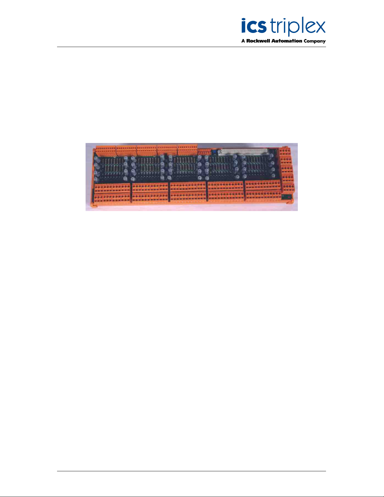
Figure 1 T8842 Layout
Issue 8 Aug 12 PD-T8842 3
Page 4

Trusted
TM
Versatile FTA T8842
Table of Contents
1. Description ................................................................................................................................... 8
1.1. Digital Inputs (Powered) ............................................................................................................. 10
1.2. Digital Inputs (Line Monitored) ................................................................................................... 11
1.3. Digital Output ............................................................................................................................. 12
1.4. Analogue inputs (4-20mA) ......................................................................................................... 13
1.5. Fire Input Loops ......................................................................................................................... 14
1.6. Monitored Valve Outputs ........................................................................................................... 15
2. Installation .................................................................................................................................. 16
3. Associated Cable Selection ....................................................................................................... 16
4. Assembly Pinout Connections ................................................................................................... 16
4.1. TBFP1 to TBFP5 Connections .................................................................................................. 17
4.2. TBG1 Connections .................................................................................................................... 17
4.3. TBG2 Connections .................................................................................................................... 18
4.4. TBG3 Connections .................................................................................................................... 18
4.5. TBG4 Connections .................................................................................................................... 19
4.6. TBG5 Connections .................................................................................................................... 19
4.7. TBSS Connections..................................................................................................................... 20
4.8. TB1 to TB40 Connections .......................................................................................................... 20
4.9. Links........................................................................................................................................... 21
5. Specifications ............................................................................................................................. 22
Issue 8 Aug 12 PD-T8842 4
Page 5

Trusted
TM
Versatile FTA T8842
Figures
Figure 1 T8842 Layout .............................................................................................................................. 3
Figure 2 Layout for single channel showing all components .................................................................... 8
Figure 3 Power Group Configuration ........................................................................................................ 9
Figure 4 Digital Inputs (with power) ........................................................................................................ 10
Figure 5 Digital Inputs (Line Monitored without power) .......................................................................... 11
Figure 6 Digital Outputs .......................................................................................................................... 12
Figure 7 Current Sourcing Analogue Inputs ........................................................................................... 13
Figure 8 Fire Inputs ................................................................................................................................. 14
Figure 9 Position Limit Switches and circuit ........................................................................................... 15
Figure 10 Voltage Input with Limit Switch Position ................................................................................. 15
Figure 11 Connector Locations............................................................................................................... 16
Figure 12 Link Detail (for first group) ...................................................................................................... 21
Figure 13 Resistor Forming .................................................................................................................... 21
Tables
Table 1 TBFP1 to TBFP5 Connections .................................................................................................. 17
Table 2 TBG1 Connections .................................................................................................................... 17
Table 3 TBG2 Connections .................................................................................................................... 18
Table 4 TBG3 Connections .................................................................................................................... 18
Table 5 TBG4 Connections .................................................................................................................... 19
Table 6 TBG5 Connections .................................................................................................................... 19
Table 7 TBSS Connections .................................................................................................................... 20
Table 8 TB1 to TB40 Connections ......................................................................................................... 20
Issue 8 Aug 12 PD-T8842 5
Page 6

Trusted
TM
Versatile FTA T8842
Notice
The content of this document is confidential to ICS Triplex Technology Ltd. companies and their
partners. It may not be given away, lent, resold, hired out or made available to a third party for any
purpose without the written consent of ICS Triplex Technology Ltd.
This document contains proprietary information that is protected by copyright. All rights are reserved.
Microsoft, Windows, Windows 95, Windows NT, Windows 2000, and Windows XP are registered
trademarks of Microsoft Corporation.
The information contained in this document is subject to change without notice. The reader should, in
all cases, consult ICS Triplex Technology Ltd. to determine whether any such changes have been
made. From time to time, amendments to this document will be made as necessary and will be
distributed by ICS Triplex Technology Ltd.
Information in this documentation set may be subject to change without notice and does not represent
a commitment on the part of ICS Triplex Technology Ltd.
The contents of this document, which may also include the loan of software tools, are subject to the
confidentiality and other clause(s) within the Integrator Agreement and Software License Agreement.
No part of this documentation may be reproduced or transmitted in any form or by any means,
electronic or mechanical, including photocopying and recording, for any purpose, without the express
written permission of ICS Triplex Technology Ltd.
Disclaimer
The illustrations, figures, charts, and layout examples in this manual are intended solely to illustrate the
text of this manual.
The user of, and those responsible for applying this equipment, must satisfy themselves as to the
acceptability of each application and use of this equipment.
This document is based on information available at the time of its publication. While efforts have been
made to be accurate, the information contained herein does not purport to cover all details or variations
in hardware or software, nor to provide for every possible contingency in connection with installation,
operation, or maintenance. Features may be described herein which are present in all hardware or
software systems. ICS Triplex Technology Ltd. assumes no obligation of notice to holders of this
document with respect to changes subsequently made.
ICS Triplex Technology Ltd. makes no representation or warranty, expressed, implied, or statutory with
respect to, and assumes no responsibility for the accuracy, completeness, sufficiency, or usefulness of
the information contained herein. No warranties of merchantability or fitness for purpose shall apply.
Issue 8 Aug 12 PD-T8842 6
Page 7

Trusted
TM
Versatile FTA T8842
Revision and Updating Policy
All new and revised information pertinent to this document shall be issued by ICS Triplex Technology
Ltd. and shall be incorporated into this document in accordance with the enclosed instructions. The
change is to be recorded on the Amendment Record of this document.
Precautionary Information
WARNING
Warning notices call attention to the use of materials, processes, methods, procedures or limits which
must be followed precisely to avoid personal injury or death.
CAUTION
Caution notices call attention to methods and procedures which must be followed to avoid damage to
the equipment.
Notes:
Notes highlight procedures and contain information to assist the user in the understanding of the
information contained in this document
Warning
RADIO FREQUENCY INTERFERENCE
Most electronic equipment is influenced by Radio Frequency Interference (RFI). Caution should be
exercised with regard to the use of portable communications equipment around such equipment.
Signs should be posted in the vicinity of the equipment cautioning against the use of portable
communications equipment.
MAINTENANCE
Maintenance must be performed only by qualified personnel, otherwise personal injury or death, or
damage to the system may be caused.
Caution
HANDLING
Under no circumstances should the module housing be removed.
Associated Documents
Product Descriptions (PD) provide product specific information.
The Safety Manual contains the recommended safety requirements for the safety system design.
The PD8082B – Toolset Suite provides specific guidance on system configuration and application
generation.
The Operator and Maintenance Manual contains general guidelines on maintenance and diagnostic
procedures.
For technical support email: support@icstriplex.com
Issue 8 Aug 12 PD-T8842 7
Page 8
Trusted
Fuse Field Power
1
TM
Versatile FTA T8842
1. Description
The TrustedTM Versatile FTA T8842 provides termination for a maximum of 40 input or output channels
from various types of field devices. The input signals may be analogue (0-20mA) or digital, whilst
output signals are digital only with the T8448 Zone Interface Module. However, the Versatile FTA
T8842 may be used with the T8480 Analogue Output module using the Digital Output configuration
shown in this document.
The 40 channels are arranged in five power groups each comprising eight channels. Each channel
circuit includes two resistors.
High power 250R 7W 1% resistors to limit short circuit current
Precision 250R 0.25W 0.1% resistors to measure analogue field current
Each circuit contains a set of link positions and can be configured with the following components
supplied with the VFTA to enable the user to set the channel for the required input or output
configuration.
50mA plug-in TE5 series fuses to protect analogue current inputs
315mA plug-in TE5 series fuses to protect digital inputs
2A plug-in TE5 series fuses to protect digital outputs or act as low resistance links
The first channel of each power group may be configured as a power source for the other seven
channels of the group, to allow fire loops to be hard reset by the application.
The cable linking the 40 channels on the TrustedTM Module to the VFTA is terminated at five 10-way
connectors (TBG1 to TBG5). The dual 24Vdc power supplies are connected to the VFTA via five 4-way
connectors (TBFP1 to TBFP5). Forty 3-way connectors are used for the field loops (TB1 to TB40).
Field
Power
TBFPn
Channel 1
Signal
TBGn
B
2
3
4
2
F
E
0V
D
C
Precision Resistor
Power Resistor
A
Signal
0V
1
Field
2
Terminals
TBn
3
m
Figure 2 Layout for single channel showing all components
Issue 8 Aug 12 PD-T8842 8
Page 9

Trusted
TM
Versatile FTA T8842
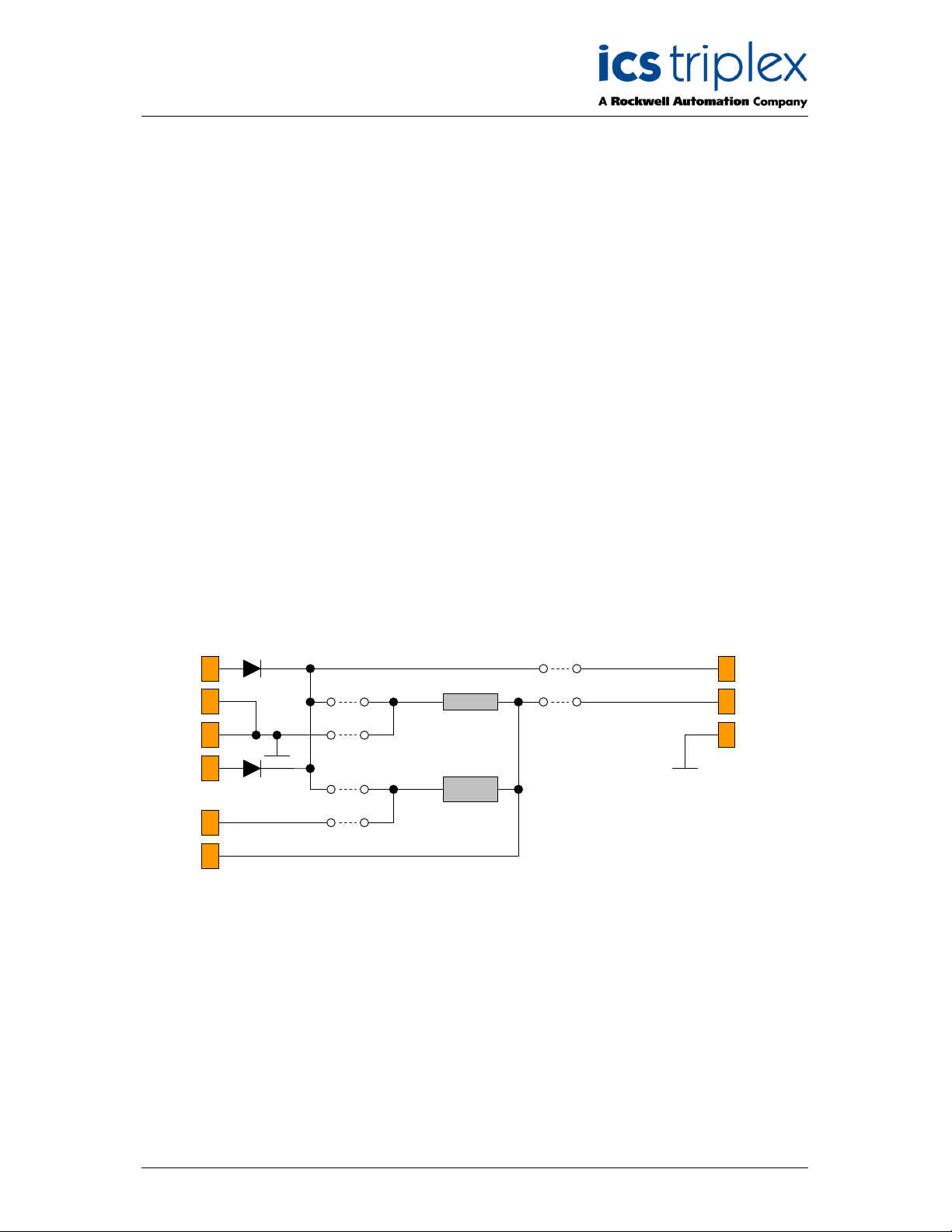
Figure 3 Power Group Configuration
The diagram above shows the full wiring for one power group of eight channels. This circuit is repeated
for each of the five power groups.
In the diagram, odd-numbered resistors are precision 250 ohms and even numbered resistors are
power 250 ohms. Links E and F cannot be fitted simultaneously, and links C and D cannot be fitted
simultaneously.
Note that 24V field power is required for a Zone Interface Module even if all channels are configured as
volt-free inputs. This may be connected via the plug at the chassis end of the cable to a T8290 or
T8297 distribution unit (for cables without power wires) or at the VFTA (for integral power cables).
Each power group is supplied from dual 24Vdc feeds which are ‘commoned’ via diodes on the VFTA.
The supply is then fed to each channel within the group. The feeds are rated at 3 amps maximum and
are designed for input circuit power.
The following sub-paragraphs detail each type of input or output configuration.
Issue 8 Aug 12 PD-T8842 9
Page 10

Trusted
Fuse Field Power
1
TM
Versatile FTA T8842
Digital Inputs (Powered)
Figure 4 shows a channel configured to accept digital input signals from the field from devices which
require power from the loop, e.g. fire input devices.
Field
Power
TBFPn
Channel 1
Signal
TBGn
B
Precision Resistor
Power Resistor
0V
F
E
2A
D
C
2
3
4
2
A
315 mA
Signal
m
0V
1
Field
2
Terminals
TBn
3
Figure 4 Digital Inputs (with power)
The configuration shown above enables powered digital input devices to be interfaced to the TrustedTM
TMR Zone Interface module. The channel is configured by fitting a 315mA fuse in position A, which
provides circuit protection. Power for the field loop is derived from the dual 24Vdc source via the 2A
fuse in position D, which acts as a link. The 250R resistor (7W 1%) allows the field device status to be
monitored via the resistor voltage drop. It also acts as a field current limiter (96mA at 24V). The
voltage at the field side of the resistor is detected by the module and used to determine the
healthy/alarm state from the field device.
For inputs which directly short the input or apply a fixed voltage (e.g. zener diode line monitoring), to a
Zone Interface or Valve Monitor module, a 1k 0.6W resistor is required in position A. This is because
the module requires an impedance to allow internal testing. Note that this will change the voltages seen
by the module.
Issue 8 Aug 12 PD-T8842 10
Page 11

Trusted
Fuse Field Power
1
TM
Versatile FTA T8842
Digital Inputs (Line Monitored)
Figure 5 shows a channel configured to accept line monitored digital input signals.
315 mA
B
Field
Power
TBFPn
2
3
4
F
E
0V
D
Precision Resistor
Power Resistor
A
Signal
2A
0V
1
Field
2
Terminals
TBn
3
Channel 1
Signal
TBGn
2
m
C
Figure 5 Digital Inputs (Line Monitored without power)
The configuration shown above enables line monitored digital input devices to be interfaced to the
TrustedTM TMR Zone Interface module (or a TMR Digital Input module). The channel is configured by
fitting a 315mA fuse in position B, which provides circuit protection. Power for the field loop is derived
from the dual 24Vdc source. The input signal is returned via a 2A fuse in position A, which acts as a
link.
For inputs without line monitoring components or using zener diodes, to a Zone Interface or Valve
Monitor module, a 1K 0.6W resistor is required in position A. This is because the module requires an
impedance to allow internal testing. Note that this will change the voltages seen by the module.
Issue 8 Aug 12 PD-T8842 11
Page 12

Trusted
Fuse Field Power
1
TM
Versatile FTA T8842
Digital Output
Figure 6 shows the configuration required to provide digital outputs to the field.
Field
Power
TBFPn
Channel 1
Signal
TBGn
B
2
3
4
2
m
F
E
0V
D
C
Precision Resistor
Power Resistor
A
Signal
2A
0V
1
Field
2
Terminals
TBn
3
Figure 6 Digital Outputs
Powered digital outputs to the field may be provided by fitting a 2A fuse in fuse position A, acting as
circuit protection. Note: The maximum output power from any single power group (8 outputs) is 8
Amps.
Issue 8 Aug 12 PD-T8842 12
Page 13

Trusted
Fuse Field Power
1
TM
Versatile FTA T8842
Analogue inputs (4-20mA)
Figure 7 below shows the configurations required to accept input signals from current sourcing
analogue field devices.
315 mA
Field
Power
TBFPn
B
Precision Resistor
Power Resistor
0V
F
E
2A
D
2
3
4
A
50 mA
Signal
0V
1
Field
2
Terminals
TBn
3
Channel 1
Signal
TBGn
2
m
C
Figure 7 Current Sourcing Analogue Inputs
The (optional) field power for each channel configured for analogue inputs is derived from the dual
24Vdc supplies via a 315mA fuse fitted in fuse position B, which provides circuit protection.
Current sourcing analogue field devices may be interfaced to the VFTA by fitting a 2A fuse in fuse
position E, which acts as a link, and a 50mA fuse in fuse position A, for circuit protection. This enables
current detection through the 250R resistor (high precision 0.1%). The fuse in fuse position A limits the
signal current to 50mA.
Current sinking analogue field devices may only be interfaced to the VFTA using a current mirror
interface. This interface may also include I.S. protection, e.g. MTL5040.
Issue 8 Aug 12 PD-T8842 13
Page 14

Trusted
Fuse Field Power
1
TM
Versatile FTA T8842
Fire Input Loops
Figure 8 below shows the configuration required to accept input signals from fire input loops. This
configuration may be used for both I.S. and non-I.S. applications.
Field
Power
TBFPn
Channel 1
Signal
TBGn
B
2
3
4
2
F
E
0V
D
C
2A
Precision Resistor
Power Resistor
A
315 mA
Signal
m
0V
1
Field
2
Terminals
TBn
3
Figure 8 Fire Inputs
Latching fire detectors are reset by the removal of field power. Using this Fire Input configuration, fire
loops can have their field power supplied from the TrustedTM module, using the first channel of a power
group as a power supply, configured as a digital output. This provides control of the field loop from the
application with no added components. The first channel must be wired as shown in Figure 6.
The supply voltage to the field loop is derived from the first channel in each power group and fed via
the 2A fuse located in fuse position C, which acts as a link. Position C is commoned to the remaining
7 channels in the associated power group. Each channel in the power group with a fire input loop
connected requires a 315mA fuse fitted in fuse position A, which provides circuit protection, and a 2A
fuse in position C, to connect to the switched field power. The 250R resistor (7W 1%) allows the field
device status to be monitored via the resistor voltage drop. It also acts as a field current limiter. The
voltage at the field side of the resistor is detected by the module and used to determine the
healthy/alarm state from the field device.
The maximum switched field supply current is 2 amps in each power group, distributed across
channels 2 to 8. The maximum loop current per channel is 96mA at 24V.
Note that the power supply channel 1 needs to be connected to a load of at least 50mA to protect the
output from no-load shutdown.
For inputs without line monitoring components or using zener diodes, to a Zone Interface or Valve
Monitor module, a 1K 0.6W resistor is required between the Signal connection and the module (in
series with the I/O cable). This is because the module requires an impedance to allow internal testing.
Note that this will change the voltages seen by the module.
Issue 8 Aug 12 PD-T8842 14
Page 15

Trusted
TM
Versatile FTA T8842
Monitored Valve Outputs
For a TrustedTM TMR Valve Monitor Module T8449, an output configuration as shown in Figure 6 is
required to drive the safety valve. The valve position is monitored by the next channel configured as an
input. This input may be an analogue position sensor, which is wired as shown in Figure 7. This input
expects a 4-20mA current loop from the position sensor. It may also be wired from a set of limit
switches arranged in a resistor network. This network is powered from 24V and received as a voltage
input as in Figure 5. The network should be arranged so that the voltage seen at the channel input
passes through a series of steps as the switches are activated in turn. The steps should continue in
one direction through the whole valve travel, or the valve monitor module will not be able to determine
the valve position.
The diagrams below shows an example switched voltage circuit, using Open, Nearly Open and Closed
switches. Each switch is wired to close to the clockwise side of travel (note: ‘O’ will close when ‘not
open’). The resistor values shown will ensure that the lowest value resistor will override the state of the
others. The thresholds are programmed into the module System.INI and set the target states for the
valve test. They also allow room for open and short circuit detection.
24V
1
2
0V
3
O
NO C
O
NO
20.4
12.8
5.7
2.2
C
10K
1K2
220R 4K7
1K
Figure 9 Position Limit Switches and circuit
V
Figure 10 Voltage Input with Limit Switch Position
closed
Threshold 18V
travel
Threshold 10V
nearly open
Threshold 4V
open
Issue 8 Aug 12 PD-T8842 15
Page 16

Trusted
TBG1 TBG2 TBG3 TBG4 TBG5 TBSS
TB1
TB2
TB3
TB4
TB5
TB6
TB7
TB8
TB9
TB10
TB11
TB12
TB13
TB14
TB15
TB16
TB17
TB18
TB19
TB20
TB21
TB22
TB23
TB24
TB25
TB26
TB27
TB28
TB29
TB30
TB31
TB32
TB33
TB34
TB35
TB36
TB37
TB38
TB39
TB40
TM
Versatile FTA T8842
2. Installation
The TrustedTM Versatile FTA 8842 is designed to be mounted on either of the TS32 or TS35 DIN rails
in the horizontal or vertical positions as required.
3. Associated Cable Selection
Note that 24V field power is required even if all channels are configured as inputs. This may be
connected via the plug at the chassis end of the cable to a T8290 or T8297 distribution unit (for cables
without power wires) or at the VFTA (for integral power cables).
Refer to the product descriptions detailed below:
PD-TC000 TrustedTM Power Cables
PD-TC200 TrustedTM I/O Companion Slot Cables
PD-TC500 TrustedTM I/O SmartSlot Cables
4. Assembly Pinout Connections
1 2 3
Figure 11 Connector Locations
TBFP1
TBFP2
TBFP3
TBFP4
TBFP5
4 3 2 1
Issue 8 Aug 12 PD-T8842 16
Page 17

Trusted
TM
Versatile FTA T8842
TBFP1 to TBFP5 Connections
The pin connections of TBFP1 to TBFP5 are identical and are detailed below:
Pin Service
1 24V-1
2 0V
3 0V
4 24V-2
Table 1 TBFP1 to TBFP5 Connections
Note that the 0V for each group are interconnected on the VFTA.
TBG1 Connections
Pin Service
1 0V
2 Channel 1
3 Channel 2
4 Channel 3
5 Channel 4
6 Channel 5
7 Channel 6
8 Channel 7
9 Channel 8
10 0V (Not used)
Table 2 TBG1 Connections
Issue 8 Aug 12 PD-T8842 17
Page 18

Trusted
TM
Versatile FTA T8842
TBG2 Connections
Pin Service
1 0V
2 Channel 9
3 Channel 10
4 Channel 11
5 Channel 12
6 Channel 13
7 Channel 14
8 Channel 15
9 Channel 16
10 0V (Not used)
Table 3 TBG2 Connections
TBG3 Connections
Pin Service
1 0V
2 Channel 17
3 Channel 18
4 Channel 19
5 Channel 20
6 Channel 21
7 Channel 22
8 Channel 23
9 Channel 24
10 0V (Not used)
Table 4 TBG3 Connections
Issue 8 Aug 12 PD-T8842 18
Page 19

Trusted
TM
Versatile FTA T8842
TBG4 Connections
Pin Service
1 0V
2 Channel 25
3 Channel 26
4 Channel 27
5 Channel 28
6 Channel 29
7 Channel 30
8 Channel 31
9 Channel 32
10 0V (Not used)
Table 5 TBG4 Connections
TBG5 Connections
Pin Service
1 0V
2 Channel 33
3 Channel 34
4 Channel 35
5 Channel 36
6 Channel 37
7 Channel 38
8 Channel 39
9 Channel 40
10 0V (Not used)
Table 6 TBG5 Connections
Issue 8 Aug 12 PD-T8842 19
Page 20

Trusted
TM
Versatile FTA T8842
TBSS Connections
Pin Service
1 Auxiliary Input (Not used)
2 Auxiliary Input (Not used)
3 Smart Slot A (Not used)
4 Smart Slot B (Not used)
5 Smart Slot C (Not used)
6 Channel 41
7 Channel 0
Table 7 TBSS Connections
TB1 to TB40 Connections
The pin connections of TB1 to TB40 are identical and are detailed below:
Pin Service
1 Field power
2 Signal in
3 0V
Table 8 TB1 to TB40 Connections
Issue 8 Aug 12 PD-T8842 20
Page 21

Trusted
TM
Versatile FTA T8842
Links
Links 1 to 6 are not used in this configuration and should be fitted in position B or removed.
Links 1 to 5 wire power from each group to the unused TBSS terminals 2 and 7. Link 6 wires TBSS
terminals 1 and 6 to zero volts. SmartSlot operation is no longer performed on the VFTA and therefore
the links should not be fitted.
Each channel has a set of links to configure the conditioning circuit, as referenced on the previous
pages. These are detailed below.
Links F1 to F8
Links E1 to E8
Links D1 to D8
Links C1 to C8
Links B1 to B8
Links A1 to A8
1 2 3 4 5 6 7 8
Figure 12 Link Detail (for first group)
Note: The pitch and spacing of the links prevent invalid configuration if the fuses supplied with the
VFTA are used.
Groups 2 to 5 are arranged in the same way. The channel links are numbered on the PCB.
Where 1K resistors are required as described in this document, the resistor leads should be formed as
shown below.
Figure 13 Resistor Forming
Issue 8 Aug 12 PD-T8842 21
Page 22

Trusted
TM
Versatile FTA T8842
5. Specifications
Voltage Range (Field Supply)
Fuses
Maximum Current (Field Supply)
Recommended Operating Current (Field Supply)
Power Consumption (Field Supply)
Signal Input Range
Operating Temperature
Non-operating Temperature
Operating Humidity
Environmental Specifications
Dimensions
Height
Width
Depth (including mounting rail and connectors)
Weight
18 to 28Vdc
40-off 2A plug-in TE-5 series, ICS part
number 813409
40-off 315mA plug-in TE-5 series, ICS
part number 813407
40-off 50mA plug-in TE-5 series, ICS
part number 813405
2.52A per power group
220mA per channel
9W maximum
0-20mA
-50C to 600C (230F to 1400F)
-250C to 700C (-130F to 1580F)
5 to 95% RH non-condensing
Refer to Document. 552517
110mm (4.33ins)
360mm (14.17ins)
68mm (2.67ins)
950gms (2.1lbs)
Issue 8 Aug 12 PD-T8842 22
Page 23

Trusted
TM
Versatile FTA T8842
This page is intentionally blank
Issue 8 Aug 12 PD-T8842 23
Page 24

 Loading...