

Page 1

TrustedTM
PD-T8841
TM
Trusted
8 Channel RTD FTA
Introduction
M
The Trusted
to eight Platinum 100R RTD sensors which may be connected using two or 3-wire configurations.
Each RTD FTA channel may be configured to provide either a scaled current output in the range of
4-20mA, or a scaled voltage output in the range of 1-5V dc. The RTD FTA also provides sensor
excitation and linearisation for each channels.
T
8 Channel RTD FTA T8841 provides an interface between a Trusted
Features
• Eight input channels per RTD FTA
M
T
System and up
• Industry standard field device connections
• Standard DIN rail compatibility
• Simple installation and connection
• 24V dc operation
• Configurable 2 or 3-wire inputs
• Configurable current or voltage output
Issue 6 Nov 07 PD-T8841 1
Page 2

Trusted
Issue Record
Issue
Number Date Revised by Technical CheckAuthorised by Modification
5 Sep 05 J W Clark Format
6 Nov 07 N Owens A Holgate P Stock Cable advice
TM
RTD FTA T8841
Issue 6 Nov 07 PD-T8841 2
Page 3
Trusted
TM
RTD FTA T8841
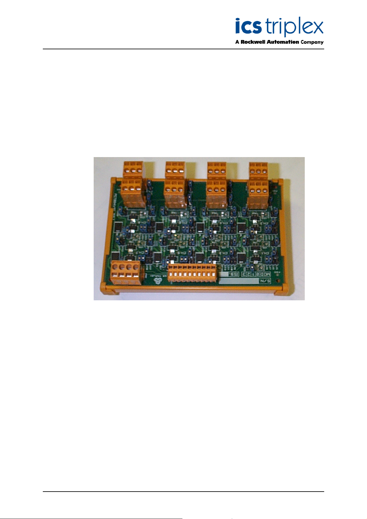
Figure 1 T8841 Layout
Issue 6 Nov 07 PD-T8841 3
Page 4

Trusted
TM
RTD FTA T8841
Table of Contents
1. Description ...................................................................................................................................7
2. System Functions ........................................................................................................................8
2.1. Zero, Gain & Linearisation ...........................................................................................................8
3. Installation....................................................................................................................................8
3.1. Cable Selection ............................................................................................................................8
4. Assembly Pinout Connections ...................................................................................................11
4.1. RTD1 to RTD8 ...........................................................................................................................11
4.2. IOIF............................................................................................................................................11
4.3. PWR ..........................................................................................................................................11
5. Link Assignments.......................................................................................................................12
5.1. Two Wire Operation...................................................................................................................12
5.2. Voltage Output ...........................................................................................................................12
5.3. Measurement range 0 to 1000C.................................................................................................13
5.4. Measurement range 0 to 3000C.................................................................................................13
6. Specifications.............................................................................................................................14
Figures
Figure 1 T8841 Layout..............................................................................................................................3
Figure 2 Single Channel Circuit ................................................................................................................7
Figure 3 Typical configuration...................................................................................................................9
Figure 4 Configuration using VFTA ........................................................................................................10
Table s
Table 1 RTD Connections ......................................................................................................................11
Table 2 IOIF Connections.......................................................................................................................11
Table 3 PWR Connections .....................................................................................................................11
Table 4 Two Wire Link Assignments ......................................................................................................12
Table 5 Voltage Output Link Assignments .............................................................................................12
Table 6 Range 0 to 100 deg C Link Assignments ..................................................................................13
Table 7 Range 0 to 300 deg C Link Assignments ..................................................................................13
Issue 6 Nov 07 PD-T8841 4
Page 5

Trusted
TM
RTD FTA T8841
Notice
The content of this document is confidential to ICS Triplex Technology Ltd. companies and their
partners. It may not be given away, lent, resold, hired out or made available to a third party for any
purpose without the written consent of ICS Triplex Technology Ltd.
This document contains proprietary information that is protected by copyright. All rights are reserved.
Microsoft, Windows, Windows 95, Windows NT, Windows 2000, and Windows XP are registered
trademarks of Microsoft Corporation.
The information contained in this document is subject to change without notice. The reader should, in
all cases, consult ICS Triplex Technology Ltd. to determine whether any such changes have been
made. From time to time, amendments to this document will be made as necessary and will be
distributed by ICS Triplex Technology Ltd.
Information in this documentation set may be subject to change without notice and does not represent
a commitment on the part of ICS Triplex Technology Ltd.
The contents of this document, which may also include the loan of software tools, are subject to the
confidentiality and other clause(s) within the Integrator Agreement and Software License Agreement.
No part of this documentation may be reproduced or transmitted in any form or by any means,
electronic or mechanical, including photocopying and recording, for any purpose, without the express
written permission of ICS Triplex Technology Ltd.
Disclaimer
The illustrations, figures, charts, and layout examples in this manual are intended solely to illustrate the
text of this manual.
The user of, and those responsible for applying this equipment, must satisfy themselves as to the
acceptability of each application and use of this equipment.
This document is based on information available at the time of its publication. While efforts have been
made to be accurate, the information contained herein does not purport to cover all details or variations
in hardware or software, nor to provide for every possible contingency in connection with installation,
operation, or maintenance. Features may be described herein which are present in all hardware or
software systems. ICS Triplex Technology Ltd. assumes no obligation of notice to holders of this
document with respect to changes subsequently made.
ICS Triplex Technology Ltd. makes no representation or warranty, expressed, implied, or statutory with
respect to, and assumes no responsibility for the accuracy, completeness, sufficiency, or usefulness of
the information contained herein. No warranties of merchantability or fitness for purpose shall apply.
Issue 6 Nov 07 PD-T8841 5
Page 6

Trusted
TM
RTD FTA T8841
Revision and Updating Policy
All new and revised information pertinent to this document shall be issued by ICS Triplex Technology
Ltd. and shall be incorporated into this document in accordance with the enclosed instructions. The
change is to be recorded on the Amendment Record of this document.
Precautionary Information
WARNING
Warning notices call attention to the use of materials, processes, methods, procedures or limits which
must be followed precisely to avoid personal injury or death.
CAUTION
Caution notices call attention to methods and procedures which must be followed to avoid damage to
the equipment.
Notes:
Notes highlight procedures and contain information to assist the user in the understanding of the
information contained in this document
Warning
RADIO FREQUENCY INTERFERENCE
Most electronic equipment is influenced by Radio Frequency Interference (RFI). Caution should be
exercised with regard to the use of portable communications equipment around such equipment.
Signs should be posted in the vicinity of the equipment cautioning against the use of portable
communications equipment.
MAINTENANCE
Maintenance must be performed only by qualified personnel, otherwise personal injury or death, or
damage to the system may be caused.
Caution
HANDLING
Under no circumstances should the module housing be removed.
Associated Documents
Product Descriptions (PD) provide product specific information.
The Safety Manual contains the recommended safety requirements for the safety system design.
The PD8082B – Toolset Suite provides specific guidance on system configuration and application
generation.
The Operator and Maintenance Manual contains general guidelines on maintenance and diagnostic
procedures.
For technical support email: support@icstriplex.com
Issue 6 Nov 07 PD-T8841 6
Page 7

Trusted
TM
RTD FTA T8841
1. Description
Figure 2 shows a single channel of the RTD FTA. All eight channels are identical.
Figure 2 Single Channel Circuit
Each channel of the RTD FTA contains a precision RTD instrumentation amplifier circuit based on the
Burr Brown XTR105 device. The device is a monolithic 4-20mA, 2-wire current transmitter with two
precision current sources. It provides complete current excitation for Platinum RTD temperature
sensors and bridges, an instrumentation amplifier and current output circuits on a single integrated
circuit.
The amplifier gain can be configured for a wide range of temperature measurements. Total
unadjusted error of the complete current transmitter is low enough to permit use without adjustment in
many applications. This includes zero output current drift, span drift and non-linearity.
Each circuit contains configuration links allowing user selection of the following:
1. Input temperature measurement range.
2. Two and three wire input sensor operation.
3. Voltage output when appropriate links are fitted.
4. Amplifier gain.
5. Linear resistors.
6. Zero resistors.
The input temperature measurement range is individually configurable on each channel. The minimum
temperature setting for each of the two configurable ranges per channel can be factory pre-set over the
range -200
per channel can be factory pre-set over the range 100
0
C to 8000C. The temperature measurement range for each of the two configurable ranges
0
C to 10000C.
Issue 6 Nov 07 PD-T8841 7
Page 8

Trusted
Each RFTA temperature output is configurable for the following:
The 4-20mA current source output is the preferred option. The 0-5V dc option provides an overall
operating range of 0-5V dc with a healthy field loop operating range of 1-5V dc.
TD devices in the field are connected to the RTD FTA by cables terminated at eight 3-way
R
connectors (RTD1 to RTD8). The eight temperature outputs from the RFTA is via a 10-way connector
(IOIF). The dual 24V dc power supplies are connected to the RFTA via a 4- way connector (PWR).
TM
RTD FTA T8841
1. 4-20mA current source output.
2. 0-5V dc voltage source output.
2. System Functions
2.1. Zero, Gain & Linearisation
The RTD linearisation for each channel is controlled by two factory pre-set linearisation resistances,
RLIN1 and RLIN2. These values are dependent upon the zero and full scale settings required for that
channel. Each channel has provision for two separate link selectable values for both RLIN1 and
RLIN2.
The zero setting for each channel is controlled by the factory pre-set zero resistance, Rz. Each
channel has provision for two separate link selectable values for Rz.
The full scale setting for each channel is controlled by the factory pre-set gain resistor Rg. Each
channel has provision for four separate link selectable values for Rg.
3. Installation
The TrustedTM 8 Channel RTD FTA T8841 is designed to be mounted on either of the TS32 or TS35
DIN rails in the horizontal or vertical positions.
3.1. Cable Selection
The TrustedTM 8 Channel RTD FTA can connect direct to an Analogue Input Module using either
companion cables TC-211/212 or smart-slot cables TC-511/512. The Output can also be connected to
the Analogue Input module via a VFTA if necessary to be compatible with an existing installation,
where complete groups of channels can be wired to T8841 FTAs or other inputs as required.
Issue 6 Nov 07 PD-T8841 8
Page 9

Trusted
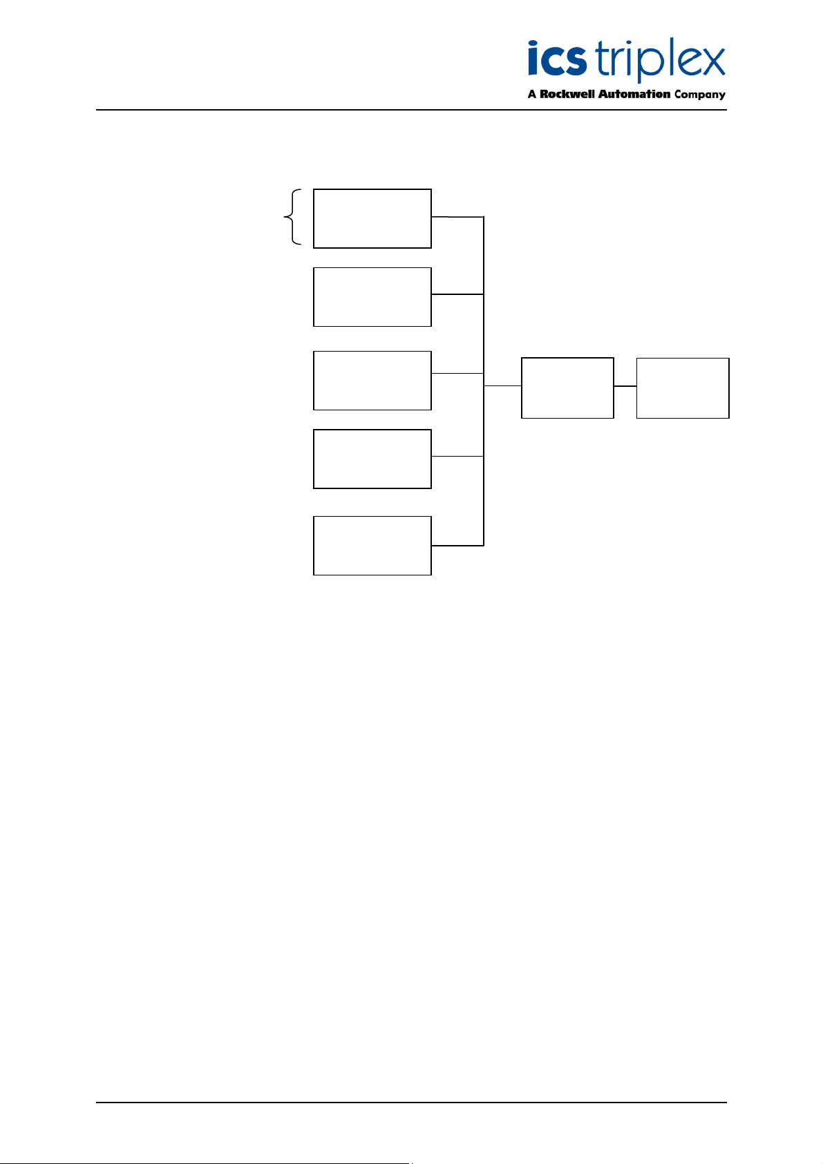
8431
TC-211/212
TM
Up to 8 RTD devices
RTD FTA T8841
RTD FTA
8841
RTD FTA
8841
RTD FTA
8841
RTD FTA
8841
RTD FTA
8841
Analogue
module
Figure 3 Typical configuration
Issue 6 Nov 07 PD-T8841 9
Page 10
Trusted
8431
TM
Up to 8 RTD devices
RTD FTA T8841
RTD FTA 8841
Or separate inputs
RTD FTA 8841
Or separate inputs
RTD FTA 8841
Or separate inputs
RTD FTA 8841
Or separate inputs
RTD FTA 8841
Or separate inputs
VFTA
8842
Analogue
module
Figure 4 Configuration using VFTA
Issue 6 Nov 07 PD-T8841 10
Page 11

Trusted
TM
RTD FTA T8841
4. Assembly Pinout Connections
4.1. RTD1 to RTD8
RTD Sensor Cable Colour
Pin Service
1 (W) + Input White White
2 (R) + Input Red Red
3 (R) I Return Red
Table 1 RTD Connections
4.2. IOIF
2-Wire 3-Wire
4.3. PWR
Pin Service
1 0V earth reference
2 Channel 1 temperature output
3 Channel 2 temperature output
4 Channel 3 temperature output
5 Channel 4 temperature output
6 Channel 5 temperature output
7 Channel 6 temperature output
8 Channel 7 temperature output
9 Channel 8 temperature output
10 0V earth reference
Table 2 IOIF Connections
Pin Service
1 24V-1
2 0V
3 0V
4 24V-2
Table 3 PWR Connections
Issue 6 Nov 07 PD-T8841 11
Page 12

Trusted
TM
RTD FTA T8841
5. Link Assignments
The functions of the links are detailed below.
5.1. Two Wire Operation
The links listed in the table below must be fitted for 2-wire operation. The RTD FTA defaults to 3-wire
operation if the links detailed are not fitted.
Channel Link
1 LK93
2 LK89
3 LK94
4 LK90
5 LK95
6 LK91
7 LK96
8 LK92
Table 4 Two Wire Link Assignments
5.2. Voltage Output
The links listed in the table below must be fitted for voltage output. The RTD FTA defaults to current
output operation if the links detailed are not fitted.
Channel Link
1 LK1
2 LK45
3 LK2
4 LK46
5 LK3
6 LK47
7 LK4
8 LK48
Table 5 Voltage Output Link Assignments
Issue 6 Nov 07 PD-T8841 12
Page 13

Trusted
TM
RTD FTA T8841
5.3. Measurement range 0 to 1000C
The links listed in the table below must be fitted to enable the RTD FTA to measure temperatures in
the range 0 to 100
0
C.
Channel Link
1 LK5, LK6, LK21, LK29, LK31,
2 LK49, LK50, LK65, LK73 LK75,
3 LK9, LK10, LK23, LK33, LK35
4 LK53, LK54, LK67, LK77, LK79
5 LK13, LK14, LK25, LK37, LK39
6 LK57, LK58, LK69, LK81, LK83
7 LK17, LK18, LK27, LK41, LK43
8 LK61, LK62, LK71, LK85, LK87
Table 6 Range 0 to 100 deg C Link Assignments
5.4. Measurement range 0 to 3000C
The links listed in the table below must be fitted to enable the RTD FTA to measure temperatures in
the range 0 to 300
0
C.
Channel Link
1 LK7, LK8, LK22, LK30, LK32
2 LK51, LK52, LK66, LK74, LK76
3 LK11, LK12, LK24, LK34, LK36
4 LK55, LK56, LK68, LK78, LK80
5 LK15, LK16, LK26, LK38, LK40
6 LK59, LK60, LK70, LK82, LK84
7 LK19, LK20, LK28, LK42, LK44
8 LK63, LK64, LK72, LK86, LK88
Table 7 Range 0 to 300 deg C Link Assignments
Issue 6 Nov 07 PD-T8841 13
Page 14

Trusted
TM
RTD FTA T8841
6. Specifications
Number of Inputs
Voltage Range
Power Isolation
Power Consumption (per channel @24V dc)
Sensor Excitation Current
Current Output (normal operating range)
Operating Temperature
Non-operating Temperature
Operating Humidity
Environmental Specifications
Dimensions
Height
Width
Depth
Weight
8 Channels (2 or 3-wire)
20 to 32V dc
±250V dc
60 to 720mW
0.8mA
4 to 20mA
-50C to 600C (230F to 1400F)
-250C to 700C (-130F to 1580F)
5 to 95% RH
Refer to Document 552517
110mm (4.3ins)
145mm (5.7ins)
68mm (2.6ins)
248gms (0.55lbs)
Issue 6 Nov 07 PD-T8841 14
Page 15

Trusted
TM
RTD FTA T8841
This page is intentionally blank
Issue 6 Nov 07 PD-T8841 15
Page 16

 Loading...