

Page 1
SDS-8834
erminals
TM
Trusted
Industrial Control System
TrustedTM 20 Channel Analogue/Digital Isolated Input FTA - T8834
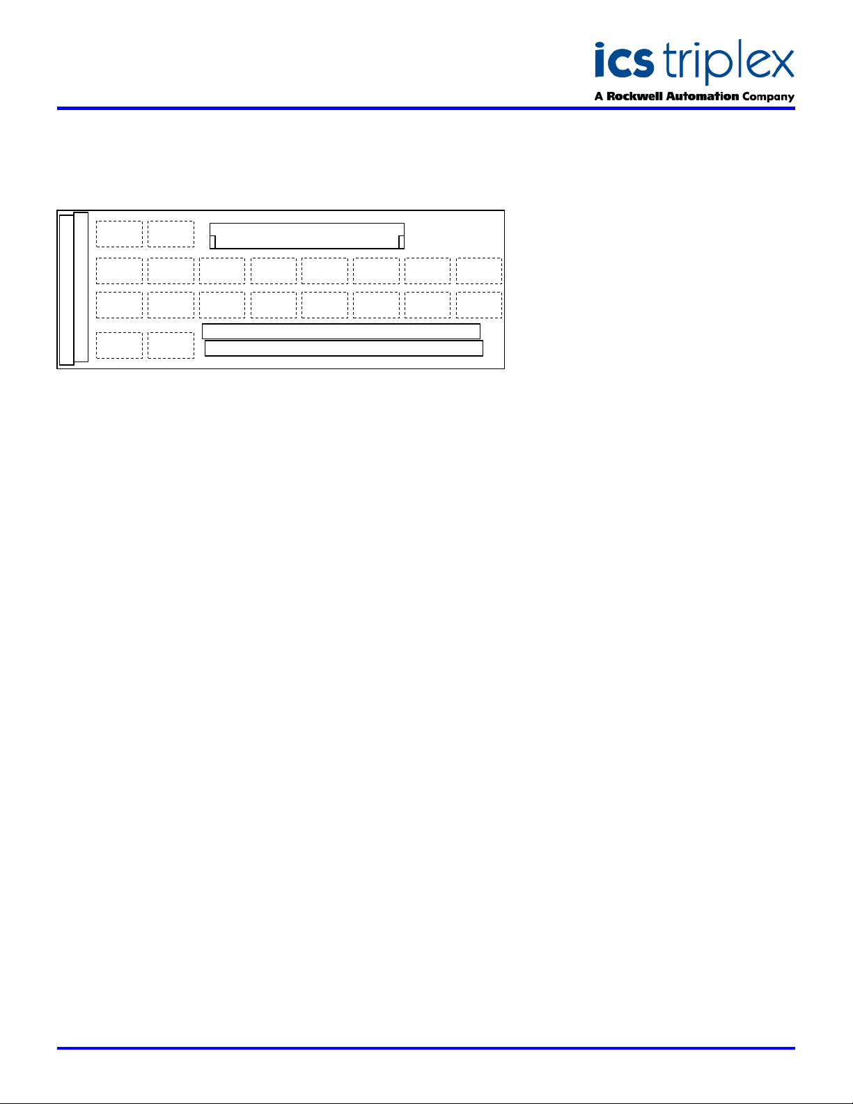
GENERAL ASSEMBLY
TB3 Screw T
Channel 1
Circuit
Channel 2
Circuit
Channel 3
Circuit
Channel 4
Circuit
Channel 5
Circuit
Channel 6
Circuit
Channel 7
Circuit
Channel 8
Circuit
Channel 9
Circuit
Channel 10
Circuit
Channel 11
Circuit
Channel 12
Circuit
CON1
DIN41612
Channel 13
Circuit
Channel 14
Circuit
TB2 Screw Terminals
TB1 Screw Terminals
Channel 15
Circuit
Channel 16
Circuit
Channel 17
Circuit
Channel 18
Circuit
Channel 19
Circuit
Channel 20
Circuit
DESCRIPTION
The Trusted
T8834 is designed to act as the main interface between a field device
generating a 4-20mA signal and the Isolated Analogue Input Module T8433.
When used with a Trusted
each of the inputs is powered from the field or FTA as required, and
individually isolated.
The FTA allows the field loop to be wired in a variety of configurations. The
field device may be connected with either three or four wire power from the
FTA, or the device may be powered locally with the module input circuit
powered from the device. The device may source current to the loop, or sink
it to the loop or to the local power supply. Four terminals are provided to
allow this versatility.
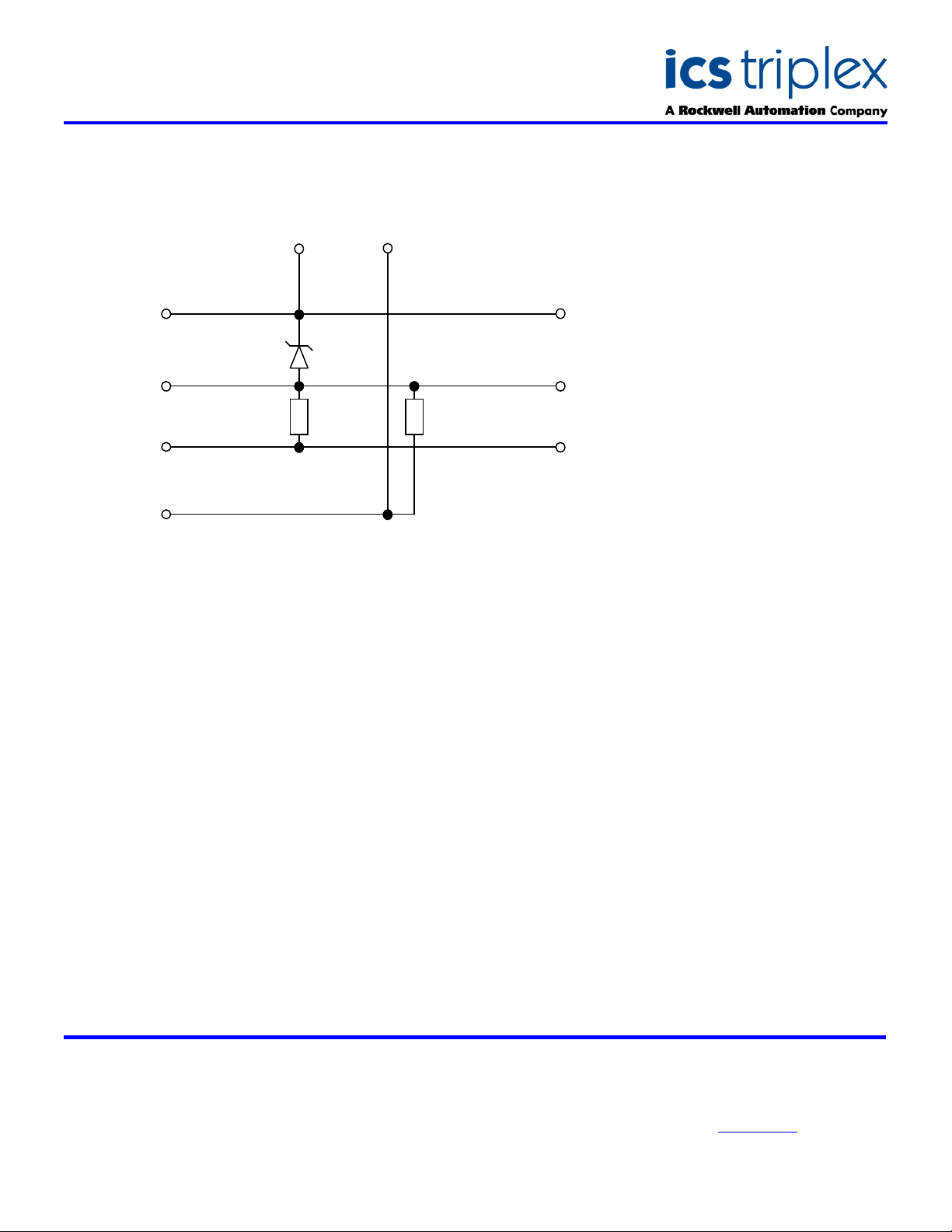
The module input circuit is powered by current passed through a zener
diode. The field input loop is fed through a 100R precision resistor to provide
a voltage measurement in the module. Each field device is isolated from the
other devices and from ground.
The cable linking the 20 channels on the input module to the FTA is
terminated at a 96-way socket. A row of eighty screw terminations is used
for the field loops, with another forty terminations providing local isolated
power connections.
The FTA is designed to be mounted on either of the TS32 or TS35 DIN rails
in the horizontal or vertical positions as required.
TM
20 Channel Isolated AI/DI FTA (Field Termination Assembly)
TM
T8433 TMR Isolated Analogue Input module
FEATURES
Twenty isolated input
channels per FTA
Standard DIN rail
compatibility
Simple installation and
connection
Versatile circuit operation
Issue 2 Jan 2006
Page 2
SDS-8834
Trusted
TM
Industrial Control System
TrustedTM 20 Channel Analogue/Digital Isolated Input FTA - T8834
BLOCK DIAGRAM
TB3 +
TB2 +
7V5
TB1 A
100R
TB1 B
TB2 -
Single Channel Schematic
ELECTRICAL SPECIFICATION
Field Current Loop (Per Channel)
Field Loop Volt Drop at 20mA
Recommended Operating Current
Power Consumption (Field Loop)
TB3 -
CON1 VPOWER
CON1 COMMON
4K75
CON1 VSENSE
0 to 30mA
9.5V if loop powered else 2V
0 to 20mA per channel
19mW maximum (if loop powering
input)
MECHANICAL
SPECIFICATION
Dimensions (HxWxD):
120mm x 336mm x 50mm
(4.7ins x 13.2ins x 2 ins)
Weight (fully populated)
500gms
(1.1lbs)
ENVIRONMENTAL
Operating Temperature:
-5°C to 60°C
(23°F to 140°F)
Operating Humidity:
5 to 95%, noncondensing
Vibration:
10 to 57Hz ±0.075mm
57 to 150Hz 1.0g
Shock:
15g, ½ sine wave, 11ms
EMI (IEC 801):
ESD
Air discharge to 15kV.
Contact discharge to 8kV
Radiated Fields
10V/m, 27MHz to
500MHz
Transients and Bursts
2kV, 2.5kHz for
t=60 seconds
ICS Triplex
Technical data sheets are intended for
information and guidance. The Company
has a policy of continual product
development and improvement.
Specifications are subject to change
without notice. For latest information, visit
our Websi te:- www.icstriplex. com
 Loading...