

Page 1

TrustedTM
PD-T8830
Introduction
Trusted
TM
40 Channel Analogue
Input FTA
The TrustedTM 40 Channel Analogue Input FTA T8830 is designed to act as the main interface
between a field device generating an analogue signal and the Trusted
T8431.
Features
• 40 input channels per FTA.
• Industry standard field device connections (2-wire).
• Standard DIN rail compatibility.
• Simple installation and connection.
• 24V dc operation.
• SmartSlot connection for ‘one to many’ hot replacement of input modules.
• Fused field power supply per channel.
• On-board LED indication field power supply integrity.
M
T
TMR Analogue Input Module
Issue 6 Dec 06 PD-T8830 1
Page 2

Trusted
Issue Record
Issue
Number Date Revised by Technical CheckAuthorised by Modification
5 Sep 05 J W Clark Format
6 Dec 06 N Owens I Vince P Stock Specifications
TM
Analogue Input FTA T8830
Issue 6 Dec 06 PD-T8830 2
Page 3
Trusted
TM
Analogue Input FTA T8830
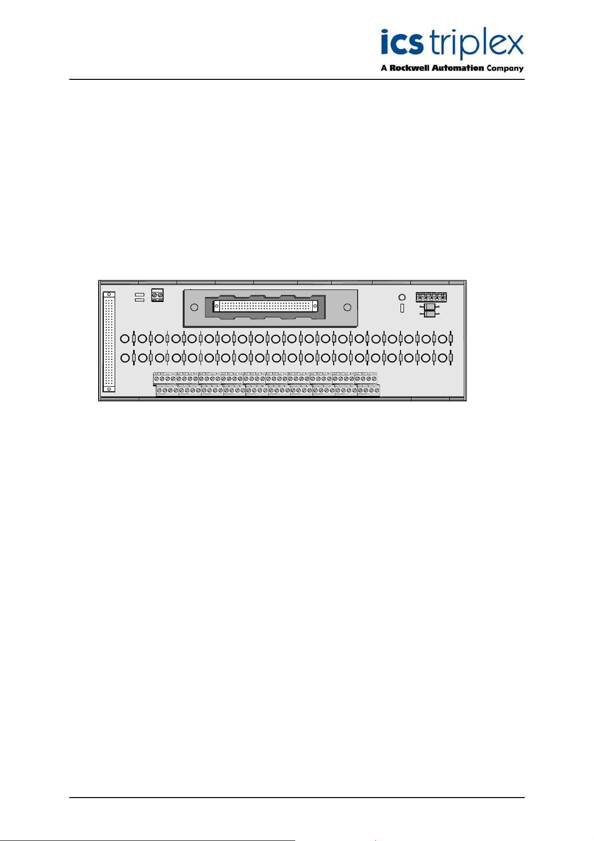
Figure 1 T8830 Layout
Issue 6 Dec 06 PD-T8830 3
Page 4

Trusted
TM
Analogue Input FTA T8830
Table of Contents
1. Description ...................................................................................................................................7
2. Installation....................................................................................................................................8
3. Associated Cable Selection .........................................................................................................8
4. Assembly Pinout Connections .....................................................................................................9
4.1. PWR TB Connections..................................................................................................................9
4.2. TB3 (Auxiliary Input) ....................................................................................................................9
4.3. TB2 (Field Terminals) ................................................................................................................10
4.4. SK1 and SK2 .............................................................................................................................11
5. Specifications.............................................................................................................................12
Figures
Figure 1 T8830 Layout..............................................................................................................................3
Figure 2 Single Channel Schematic .........................................................................................................7
Table s
Table 1 PWR TB Connections .................................................................................................................9
Table 2 TB3 (Auxiliary Input) Connections ...............................................................................................9
Table 3 TB2 (Field Terminals) Connections...........................................................................................10
Table 4 SK1 and SK2 Connections ........................................................................................................11
Issue 6 Dec 06 PD-T8830 4
Page 5

Trusted
TM
Analogue Input FTA T8830
Notice
The content of this document is confidential to ICS Triplex Technology Ltd. companies and their
partners. It may not be given away, lent, resold, hired out or made available to a third party for any
purpose without the written consent of ICS Triplex Technology Ltd.
This document contains proprietary information that is protected by copyright. All rights are reserved.
icrosoft, Windows, Windows 95, Windows NT, Windows 2000, and Windows XP are registered
M
trademarks of Microsoft Corporation.
The information contained in this document is subject to change without notice. The reader should, in
all cases, consult ICS Triplex Technology Ltd. to determine whether any such changes have been
made. From time to time, amendments to this document will be made as necessary and will be
distributed by ICS Triplex Technology Ltd.
Information in this documentation set may be subject to change without notice and does not represent
a commitment on the part of ICS Triplex Technology Ltd.
The contents of this document, which may also include the loan of software tools, are subject to the
confidentiality and other clause(s) within the Integrator Agreement and Software License Agreement.
No part of this documentation may be reproduced or transmitted in any form or by any means,
electronic or mechanical, including photocopying and recording, for any purpose, without the express
written permission of ICS Triplex Technology Ltd.
Disclaimer
The illustrations, figures, charts, and layout examples in this manual are intended solely to illustrate the
text of this manual.
The user of, and those responsible for applying this equipment, must satisfy themselves as to the
acceptability of each application and use of this equipment.
This document is based on information available at the time of its publication. While efforts have been
made to be accurate, the information contained herein does not purport to cover all details or variations
in hardware or software, nor to provide for every possible contingency in connection with installation,
operation, or maintenance. Features may be described herein which are present in all hardware or
software systems. ICS Triplex Technology Ltd. assumes no obligation of notice to holders of this
document with respect to changes subsequently made.
ICS Triplex Technology Ltd. makes no representation or warranty, expressed, implied, or statutory with
respect to, and assumes no responsibility for the accuracy, completeness, sufficiency, or usefulness of
the information contained herein. No warranties of merchantability or fitness for purpose shall apply.
Issue 6 Dec 06 PD-T8830 5
Page 6

Trusted
TM
Analogue Input FTA T8830
Revision and Updating Policy
All new and revised information pertinent to this document shall be issued by ICS Triplex Technology
Ltd. and shall be incorporated into this document in accordance with the enclosed instructions. The
change is to be recorded on the Amendment Record of this document.
Precautionary Information
WARNING
Warning notices call attention to the use of materials, processes, methods, procedures or limits which
must be followed precisely to avoid personal injury or death.
CAUTION
Caution notices call attention to methods and procedures which must be followed to avoid damage to
the equipment.
Notes:
Notes highlight procedures and contain information to assist the user in the understanding of the
information contained in this document
Warning
RADIO FREQUENCY INTERFERENCE
Most electronic equipment is influenced by Radio Frequency Interference (RFI). Caution should be
exercised with regard to the use of portable communications equipment around such equipment.
Signs should be posted in the vicinity of the equipment cautioning against the use of portable
communications equipment.
MAINTENANCE
Maintenance must be performed only by qualified personnel, otherwise personal injury or death, or
damage to the system may be caused.
Caution
HANDLING
Under no circumstances should the module housing be removed.
Associated Documents
Product Descriptions (PD) provide product specific information.
The Safety Manual contains the recommended safety requirements for the safety system design.
The PD8082B – Toolset Suite provides specific guidance on system configuration and application
generation.
The Operator and Maintenance Manual contains general guidelines on maintenance and diagnostic
procedures.
For technical support email: support@icstriplex.com
Issue 6 Dec 06 PD-T8830 6
Page 7
Trusted
TM
Analogue Input FTA T8830
1. Description
The TrustedTM 40 Channel Analogue Input FTA T8830 provides termination for a maximum of 40 input
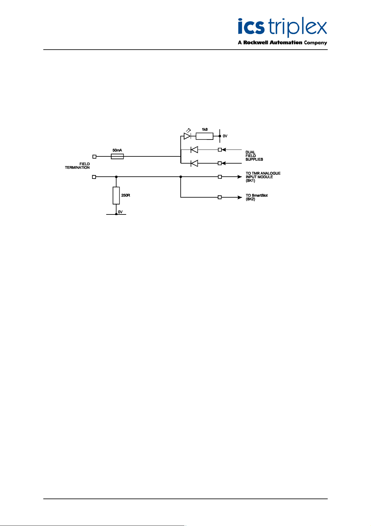
hannels from various types of field devices which generate an analogue input. Figure 2 below shows
c
the configuration of a single channel.
Figure 2 Single Channel Schematic
The supply for the field is derived from dual 24V dc feeds which are ‘commoned’ via diodes on the
FTA. Indication of the presence of the power supply is provided by a green LED. The supply is then
fed to each channel.
The supply voltage to the field is fed via the 50mA fuse. This effectively limits the current in the field
loop. The voltage developed across the 250R resistor due to the incoming analogue signal from the
field device is fed directly to the analogue input module.
The cable linking the 40 channels on the input module to the FTA is terminated at the 96-way socket
SK1. SmartSlot (Version 1) signals from the module are connected to SK1. The SmartSlot connector
is SK2 and is also a 96-way socket. This connector is not used where SmartSlot Version 2 is
employed within the Trusted
a 5-way terminal block PWR TB. The input signals from the field (40-off) are connected by 2-wire
arrangements terminated on 12-off 3-way terminal blocks and 2-off 2-way.
TM
System. The dual dc field power supplies are connected to the FTA via
Issue 6 Dec 06 PD-T8830 7
Page 8

Trusted
TM
Analogue Input FTA T8830
2. Installation
TrustedTM 40 Channel Analogue Input FTA T8830 is designed to be mounted on either of the TS32 or
S35 DIN rails in the horizontal or vertical positions as required.
T
3. Associated Cable Selection
Refer to the product descriptions detailed below:
PD-TC000 Trusted
PD-TC200 Trusted
PD-TC500 Trusted
TM
Power Cables
TM
I/O Companion Slot Cables
M
T
I/O SmartSlot Cables
Issue 6 Dec 06 PD-T8830 8
Page 9

Trusted
TM
Analogue Input FTA T8830
4. Assembly Pinout Connections
4.1. PWR TB Connections
Pin Service
1 24V-A
2 24V-B
3 0V
4 0V
5 24V (auxiliary supply for
use when required)
Table 1 PWR TB Connections
4.2. TB3 (Auxiliary Input)
Table 2 TB3 (Auxiliary Input) Connections
Pin Service
1 Chan 0 (not configured)
2 Chan 41(not configured)
Issue 6 Dec 06 PD-T8830 9
Page 10

Trusted
TM
Analogue Input FTA T8830
4.3. TB2 (Field Terminals)
Pin Service Pin Service
1
3
5
7
9
11
13
15
17
19
21
23
25
27
29
31
33
35
37
39
41
43
45
47
49
51
53
55
57
59
61
63
65
67
69
71
73
75
77
79
Chan 1 24V dc field supply
Chan 2 24V dc field supply
Chan 3 24V dc field supply
Chan 4 24V dc field supply
Chan 5 24V dc field supply
Chan 6 24V dc field supply
Chan 7 24V dc field supply
Chan 8 24V dc field supply
Chan 9 24V dc field supply
Chan 10 24V dc field supply
Chan 11 24V dc field supply
Chan 12 24V dc field supply
Chan 13 24V dc field supply
Chan 14 24V dc field supply
Chan 15 24V dc field supply
Chan 16 24V dc field supply
Chan 17 24V dc field supply
Chan 18 24V dc field supply
Chan 19 24V dc field supply
Chan 20 24V dc field supply
Chan 21 24V dc field supply
Chan 22 24V dc field supply
Chan 23 24V dc field supply
Chan 24 24V dc field supply
Chan 25 24V dc field supply
Chan 26 24V dc field supply
Chan 27 24V dc field supply
Chan 28 24V dc field supply
Chan 29 24V dc field supply
Chan 30 24V dc field supply
Chan 31 24V dc field supply
Chan 32 24V dc field supply
Chan 33 24V dc field supply
Chan 34 24V dc field supply
Chan 35 24V dc field supply
Chan 36 24V dc field supply
Chan 37 24V dc field supply
Chan 38 24V dc field supply
Chan 39 24V dc field supply
Chan 40 24V dc field supply
2 Chan 1 signal from field
4 Chan 2 signal from field
6 Chan 3 signal from field
8 Chan 4 signal from field
10 Chan 5 signal from field
12 Chan 6 signal from field
14 Chan 7 signal from field
16 Chan 8 signal from field
18 Chan 9 signal from field
20 Chan 10 signal from field
22 Chan 11 signal from field
24 Chan 12 signal from field
26 Chan 13 signal from field
28 Chan 14 signal from field
30 Chan 15 signal from field
32 Chan 16 signal from field
34 Chan 17 signal from field
36 Chan 18 signal from field
38 Chan 19 signal from field
40 Chan 20 signal from field
42 Chan 21 signal from field
44 Chan 22 signal from field
46 Chan 23 signal from field
48 Chan 24 signal from field
50 Chan 25 signal from field
52 Chan 26 signal from field
54 Chan 27 signal from field
56 Chan 28 signal from field
58 Chan 29 signal from field
60 Chan 30 signal from field
62 Chan 31 signal from field
64 Chan 32 signal from field
66 Chan 33 signal from field
68 Chan 34 signal from field
70 Chan 35 signal from field
72 Chan 36 signal from field
74 Chan 37 signal from field
76 Chan 38 signal from field
78 Chan 39 signal from field
80 Chan 40 signal from field
Table 3 TB2 (Field Terminals) Connections
Issue 6 Dec 06 PD-T8830 10
Page 11

Trusted
TM
Analogue Input FTA T8830
4.4. SK1 and SK2
1 Smart Slot Link C Smart Slot Link B Smart Slot Link A
2
3 Chan 28 (+) Chan 14 (+) Chan 0 (+)
4 Chan 28 (+) Chan 14 (+) Chan 0 (+)
5 Chan 29 (+) Chan 15 (+) Chan 1 (+)
6 Chan 29 (+) Chan 15 (+) Chan 1 (+)
7 Chan 30 (+) Chan 16 (+) Chan 2 (+)
8 Chan 30(+) Chan 16 (+) Chan 2 (+)
9 0V 0V 0V
10 Chan 31 (+) Chan 17 (+) Chan 3 (+)
11 Chan 31 (+) Chan 17 (+) Chan 3 (+)
12 Chan 32 (+) Chan 18 (+) Chan 4 (+)
13 Chan 32 (+) Chan 18 (+) Chan 4 (+)
14 Chan 33 (+) Chan 19 (+) Chan 5 (+)
15 Chan 33 (+) Chan 19 (+) Chan 5 (+)
16 Chan 34 (+) Chan 20 (+) Chan 6 (+)
17 Chan 34 (+) Chan 20 (+) Chan 6 (+)
18 Chan 35 (+) Chan 21 (+) Chan 7 (+)
19 Chan35 (+) Chan 21 (+) Chan 7 (+)
20 0V 0V 0V
21 Chan 36 (+) Chan 22 (+) Chan 8 (+)
22 Chan 36 (+) Chan 22 (+) Chan 8 (+)
23 Chan 37 (+) Chan 23 (+) Chan 9 (+)
24 Chan 37 (+) Chan 23 (+) Chan 9 (+)
25 Chan 38 (+) Chan 24 (+) Chan 10 (+)
26 Chan 38 (+) Chan 24 (+) Chan 10 (+)
27 Chan 39 (+) Chan 25 (+) Chan 11 (+)
28 Chan 39 (+) Chan 25 (+) Chan 11 (+)
29 Chan 40 (+) Chan 26 (+) Chan 12 (+)
30 Chan 40 (+) Chan 26 (+) Chan 12 (+)
31 Chan 41 (+) Chan 27 (+) Chan 13 (+)
32 Chan 41 (+) Chan 27 (+) Chan 13 (+)
C B A
Table 4 SK1 and SK2 Connections
Issue 6 Dec 06 PD-T8830 11
Page 12

Trusted
TM
Analogue Input FTA T8830
5. Specifications
Voltage Range
Maximum Current (Field Supply)
Power Consumption (Field Supply)
Operating Temperature
Non-operating Temperature
Operating Humidity
Environmental Specifications
Dimensions
Height
Width
Depth
Weight
18 to 32V dc
50mA (fused) per loop
0.25W (LED power indicator)
-50C to 600C (230F to 1400F)
-250C to 700C (-130F to 1580F)
5 to 95% RH
Refer to Document 552517
111mm (4.4ins)
335mm (13.2ins)
51mm (2ins)
900gms (2lbs)
Issue 6 Dec 06 PD-T8830 12
Page 13

Trusted
TM
Analogue Input FTA T8830
This page is intentionally blank
Issue 6 Dec 06 PD-T8830 13
Page 14

 Loading...