

Page 1
SDS-8802
TrustedTM Industrial Control System
Trusted
TM
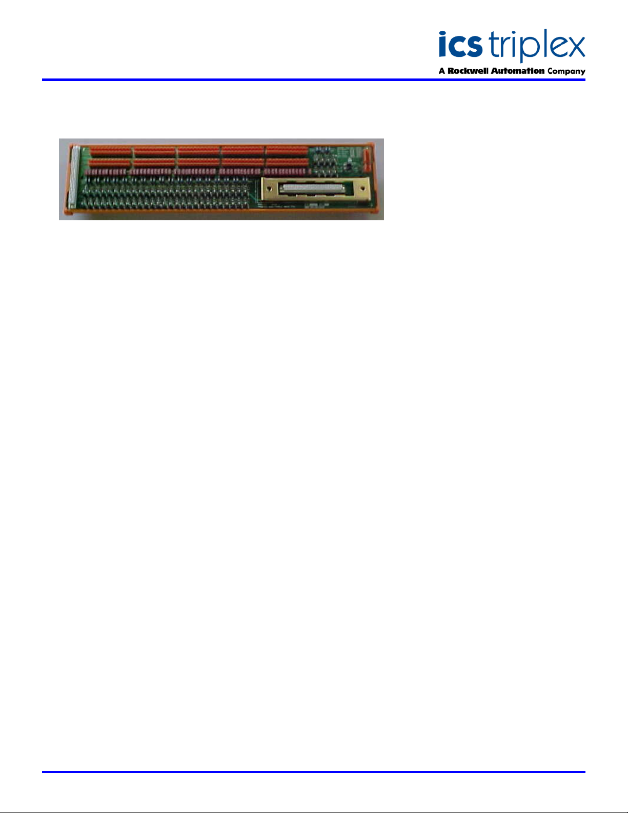
60 Channel 24V dc Digital Input FTA - T8802
GENERAL ASSEMBLY
DESCRIPTION
The Trusted
60-Channel is designed to act as the main interface between a field device
generating a digital signal and the Trusted
Module T8402.
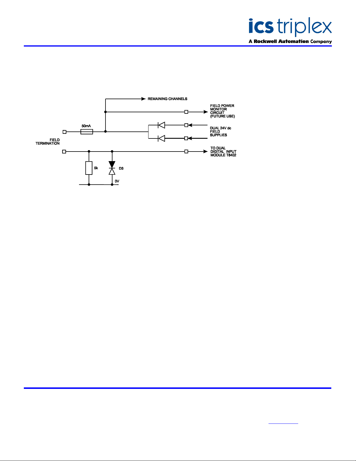
The field supply is derived from dual 24V dc feeds which are ‘commoned’ via
diodes on the FTA. The supply is then fed to each channel. Channels 0
and 61 on the Trusted
in the future to provide monitoring of the field power supply.
The supply voltage to the field is fed via a 50mA fuse. The incoming signal
(digital) from the field device is developed across a 5k/ resistor, then
connected to the appropriate input circuit on the Input Module. Line
monitoring components (if required) provide the necessary thresholds used
by the input module to detect the field loop/device status, i.e. open/short
circuit, alarm etc.
The cable linking the 60 channels on the input module to the FTA is
terminated at a 64-way socket. The dual dc power supplies are connected
to the FTA via a single 4-way connector. Ten 12-way connectors are used
for the field loops.
The VFTA is designed to be mounted on either of the TS32 or TS35 DIN
rails in the horizontal or vertical positions as required.
TM
Field Termination Assembly (FTA) 24V dc Digital Input
M
T
Dual 24V dc Digital Input
TM
Dual 24V dc Digital Input Module will be configured
FEATURES
Sixty input channels per
TA
F
Industry standard field
device connections (2-wire)
Standard DIN rail
compatibility
Simple installation and
connection
24V dc operation
Fused field power supply
per channel
Issue 4 Jan 2006
Page 2
SDS-8802
Trusted
TM
Industrial Control System
Trusted
TM
60 Channel 24V dc Digital Input FTA - T8802
BLOCK DIAGRAM
Single Channel Schematic
ELECTRICAL SPECIFICATION
Voltage Range (Field Supply)
Fuses
Maximum Current (Field Supply)
Recommended Operating Current
Power Consumption (Field Supply)
18 to 28V dc
61-off 50mA
3A
6.4mA per channel maximum
10W maximum
MECHANICAL
SPECIFICATION
Dimensions (HxWxD):
110mm x 455mm x 68mm
(4.3ins x 17.9ins x 2.6ins)
Weight (fully populated)
762gms
(1.68lbs)
ENVIRONMENTAL
Operating Temperature:
-5°C to 60°C
(23°F to 140°F)
Operating Humidity:
5 to 95%, noncondensing
Vibration:
10 to 57Hz ±0.075mm
57 to 150Hz 1.0g
Shock:
15g, ½ sine wave, 11ms
EMI (IEC 801):
ESD
Air discharge to 15kV.
Contact discharge to 8kV
Radiated Fields
10V/m, 27MHz to
500MHz
Transients and Bursts
2kV, 2.5kHz for
t=60 seconds
ICS Triplex
Technical data sheets are intended for
information and guidance. The Company
has a policy of continual product
development and improvement.
Specifications are subject to change
without notice. For latest information, visit
our Websi te:- www.icstr iple x.com
 Loading...