

Page 1
SDS-8473
TrustedTM Industrial Control System
Trusted
TM
TMR 120V ac Isolated Digital Output Module-T8473
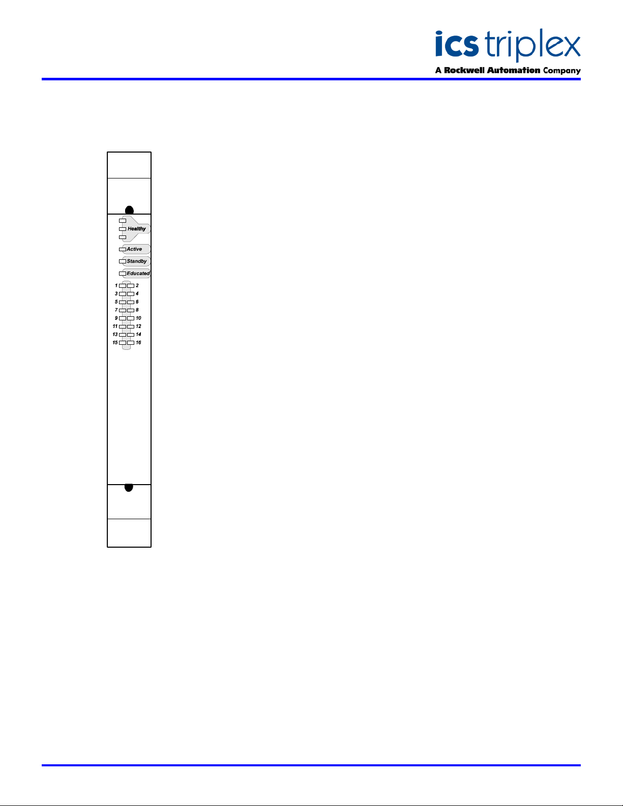
FRONT PANEL
T8473 Trusted TMR 120 Vac Isolated Output
DESCRIPTION
The Trusted
Output module interfaces to 16 field
output devices. Each output is
isolated. Fault tolerance is achieved
through Triple Modular Redundancy
(TMR) within the same module for
each of the 16 output channels.
The module provides on-board
Sequence of Events (SOE) reporting
with a resolution of 1ms. The “event”
is the actual sensing of the field
device loop current. Each triplicated
section (slice) of the module receives
output data from the Trusted
TM
TMR 120V ac Digital
TM
TMR
Processor and sends its data to an
internal safety layer hardware voter.
Each slice uses the voted data to
control the outputs. Every output
channel consists of a four-element
voted array. The output switch array
provides fault tolerant, uninterrupted
control under an output switch failure
condition. Output switching and fault
diagnostics comply with the
demanding requirements of IEC61508 SIL-3 for First Fault - Fault
Tolerant, and Second Fault - Fail
Safe outputs.
When a module fault is detected, the
Trusted
unhealthy condition, indicating the
need to replace the module. Control
continues until a replacement
(healthy) module is available.
Replacement modules can be located
in a standby slot next to the module.
Each output is user configurable to
perform line monitoring of the
connected field devices to detect field
wiring and load failures. Automatic
over-current protection is inherent in
every output circuit which eliminates
the need for fuses.
Modules may be placed in any I/O
module slot in a Trusted
Chassis or Expander chassis. Once
the I/O module configuration is set,
mechanical keying is available on all
I/O modules to prevent inserting a
module into an incorrect slot.
Configuration of the module is carried
out using the Trusted
running on an Engineering
Workstation. Once configured and
loaded into the Trusted
replacement modules are on-line
educated by the TMR Processor.
TM
TMR Processor will flag the
TM
Processor
TM
Toolset
TM
Controller,
FEATURES
Triplicated TMR system
16 Isolated Output Channels:
Comprehensive, automatic
Automatic line monitoring per
2500Vdc optical and magnetic
Automatic channel over-
On-board Sequence of Events
Module can be hot-replaced
Front panel output status
Front panel module status
IEC 61508, SIL 3 safety
architecture, with fault tolerant
output switching.
120VAC, 0.5A per channel.
diagnostics and self-test.
channel to detect open circuit
field wiring / load faults and
short circuit field wiring faults
for energised outputs.
isolation barrier.
current protection, no fuses
required.
(SOE) reporting with 1ms
resolution.
on-line using dedicated
‘Companion Slot’ (adjacent
slot).
LED’s for each channel
indicate output status and field
wiring faults.
LED’s indicate module health
and operational mode (Active,
Standby, Educated)
applications
Issue 2 Jan 2006
Page 2
SDS-8473
Inter Module Bus
Trusted
TM
Industrial Control System
Trusted
TM
TMR 120V ac Isolated Digital Output Module-T8473
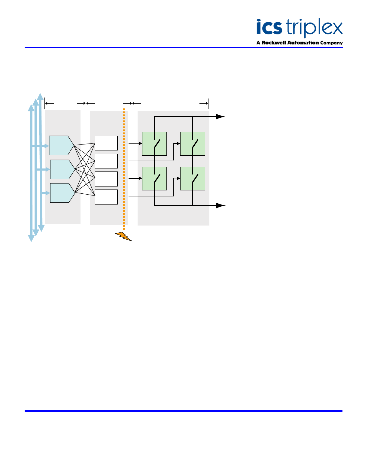
BLOCK DIAGRAM
TMR
TMR
SLICE ‘A’
TMR
SLICE ‘B’
T
MR
SLICE ‘C’
TMR
(Quad Voters)
FIU-QA
V
OTER
FIU-QB
VOTER
FIU-QC
VOTER
FIU-QD
VOTER
}
}
}
}
}
}
}
}
HIU FIU
TMR
2500V dc
ISOLATION
ELECTRICAL SPECIFICATION
Number of Outputs
Field Common Isolation
Sustained Working ±250V dc
Maximum Withstanding ±2.5kV dc
Channel to Channel Isolation
Sustained Working ±250V dc
Maximum W ithstanding ±1000V dc
Output Voltage Field Supply
Operational Range 90 to 150V ac, 47Hz < freq < 63Hz
Measurement Range 0 to 150V ac rms
Maximum Withstanding 0 to 175V ac rms
Output Maximum Current Rating
Per Channel 0.5A (8A peak, 1 AC cycle)
Power Consumption
Output Turn On/Off Delay
Self-Test Interval
Output Short Circuit Protection
Fusing
Intrinsic Safety
Circuit Type
Quad Element
Switches
QA QB
QC QD
FTU
FTU
16 Channels
20W
1.5 AC cycle max.
2 minutes
Automatic
Not required
External barrier
Fault tolerant
A
Switched
Channel
Field
Output
B
MECHANICAL
SPECIFICATION
Dimensions (HxWxD):
241mm x 30mm x 300mm
(9.5ins x 1.2ins x 11.8ins)
Weight:
1.35kg
(2.98lbs)
ENVIRONMENTAL
Operating Temperature:
-5°C to 60°C
(23°F to 140°F)
Operating Humidity:
5 to 95%, noncondensing
Vibration:
10 to 57Hz ±0.075mm
57 to 150Hz 1.0g
Shock:
15g, ½ sine wave, 11ms
EMI (IEC 801):
ESD
Air discharge to 15kV
Contact discharge to 8kV
Radiated Fields
10V/m, 27MHz to
500MHz
Transients and Bursts
2kV, 2.5kHz for
t=60 seconds
ICS Triplex
Technical data sheets are intended for
information and guidance. The Company
has a policy of continual product
development and improvement.
Specifications are subject to change
without notice. For latest information, visit
our Websi te:- www.icstr iple x.com
 Loading...