

Page 1
SDS-8471
TrustedTM Industrial Control System
Trusted
TM
TMR 120V dc Digital Output Module-T8471
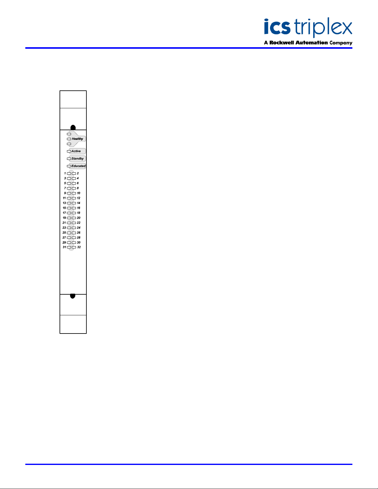
FRONT PANEL
T8471 Trusted TMR 120 Vdc Digital Output
DESCRIPTION
The Trusted
Output module interfaces to 32 field
output devices. Outputs are arranged
in four groups of eight outputs. All
outputs in a group share a common
power source and return. Fault
tolerance is achieved through Triple
Modular Redundancy (TMR) within
the same module for each of the 40
output channels.
The module provides on-board
Sequence of Events (SOE) reporting
with a resolution of 1ms. The “event”
TM
TMR 120V dc Digital
is the actual sensing of the field
device loop current
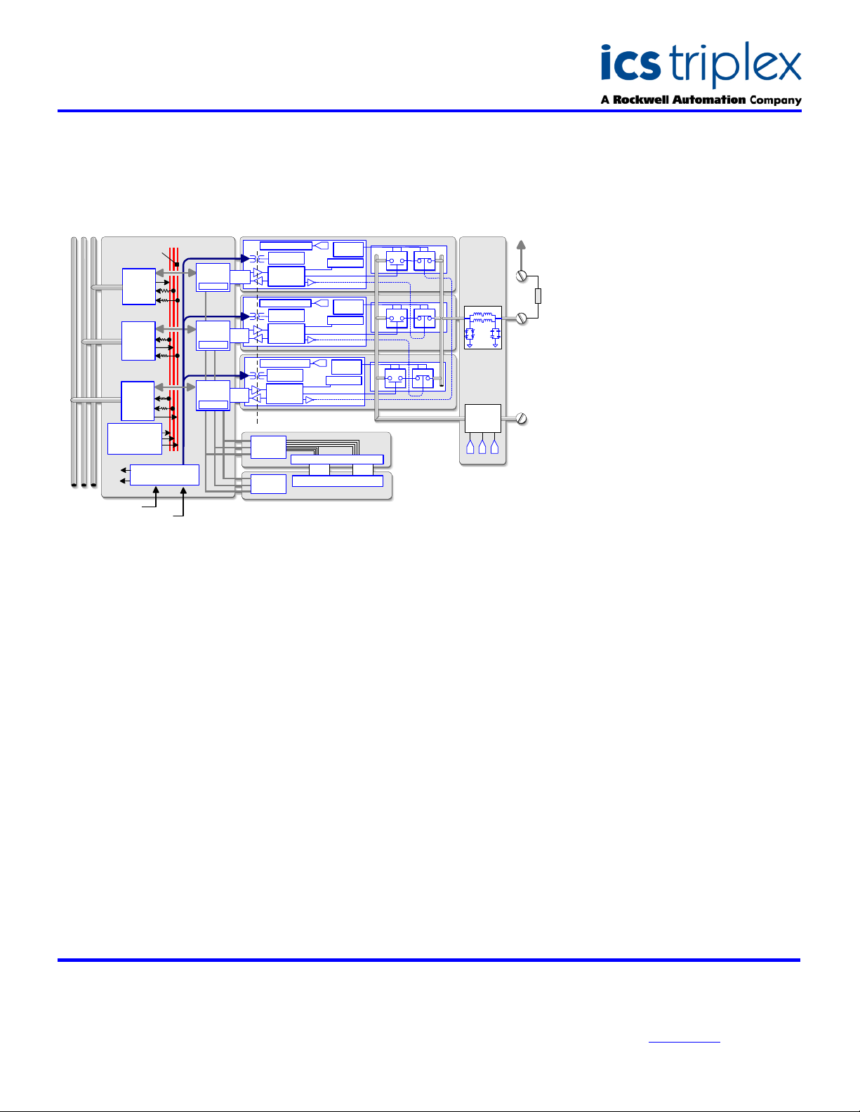
Each triplicated section (slice) of the
module receives output data from the
Trusted
its data to an internal safety layer
hardware voter. Each slice uses the
voted data to control the outputs.
Every output channel consists of a
six-element voted array. The output
switch array provides fault tolerant,
uninterrupted control under an output
switch failure condition. Output
switching and fault diagnostics
comply with the demanding
requirements of IEC-61508 SIL-3 for
First Fault - Fault Tolerant, and
Second Fault - Fail Safe outputs.
When a module fault is detected, the
Trusted
unhealthy condition, indicating the
need to replace the module. Control
continues until a replacement
(healthy) module is available.
Replacement modules can be located
in a standby slot next to the module
or in a designated SmartSlot with a
temporary connection to the same
Trusted
Each output is user configurable to
perform line monitoring of the
connected field devices to detect field
wiring and load failures. Automatic
over-current protection is inherent in
every output circuit which eliminates
the need for fuses.
Modules may be placed in any I/O
module slot in a Trusted
Chassis or Expander chassis. Once
the I/O module configuration is set,
mechanical keying is available on all
I/O modules to prevent inserting a
module into an incorrect slot.
TM
TMR Processor and sends
TM
TMR Processor will flag the
TM
Termination Assembly.
TM
Processor
Configuration of the module is carried
out using the Trusted
running on an Engineering
Workstation. Once configured and
loaded into the Trusted
replacement modules are on-line
educated by the TMR Processor.
FEATURES
TM
Toolset
TM
Controller,
32 TMR output channels per
module
Five isolated groups of eight
outputs each
Six-element voted output array
Comprehensive diagnostics
and self-test
Guaranteed, First fault – Fault
Tolerant, Second fault – Fail
Safe
Line monitoring on a per
channel basis
Automatic over-current
protection – no fuses required
2500V dc Opto-Isolation
Hot replaceable
Front panel status LEDs for
each channel
Module fault and status
indicators
IEC 61508, SIL 3 safety
applications
On-board 1 ms resolution
Sequence of Events reporting
Issue 7 Sep 2006
Page 2
SDS-8471
Trusted
TM
Industrial Control System
Trusted
TM
TMR 120V dc Digital Output Module-T8471
BLOCK DIAGRAM
OFIUHIU
Internal Voting Bus
I
Interface
TMR Intermodule Bus
Interface
Housekeeping
Module Temp
S
upply Diag
D
SP reference
B
ack Plane
Back Plane Power Bus 1
Power Bus
B
ack Plane Power Bus 2
1
B
us
nterface
Bus
B
us
R
edundant Supply
Slice
Control
ime Stamp
T
A
Slice
Control
Time Stamp
B
S
lice
C
ontrol
ime Stamp
T
B
Failsafe Bia s Control
S
lice Power
Supply
Field Logic
Control
F
ailsafe Bias Control
S
lice Power
Supply
Field Logic
Control
F
ailsafe Bias Control
lice Power
S
Supply
Field Logic
C
ontrol
Opto Isolat ion Boundary
F
ront Panel
oting Logic
V
Health
Indicators
A
D
iagnostic
Monitor
Housekeeping
B
D
iagnostic
Monitor
Housekeeping
C
iagnostic
D
Monitor
Housekeeping
S
erial Dis play Latches
V
oted Status Display LEDs
Front Pane l
ELECTRICAL SPECIFICATION
Number of Outputs
No. of Independent Power Groups
Field Common Isolation
Sustained Working ±250V dc
Maximum Withstanding ±2.5kV dc
Output Voltage Field Supply
Measurement Range 0 to 150V dc
Maximum Withstanding 0 to 200V dc
Output Maximum Current Rating
Per Channel 0.5A
Per Power Group 2A
Output Off Resistance (effective
leakage)
Power Consumption (0.5A per
channel)
Output Turn On/Off Delay
Self-Test Interval
Output Short Circuit Protection
Fusing
Intrinsic Safety
Circuit Type
32 Channels
4, each of 8outputs
330k>
12W
0.5ms
2 minutes
Automatic
Not required
External barrier
Fault tolerant, fully triplicated with
optional line monitoring
N.O.
N.O.
N.O.
FPIU
FPDU
S
lice A
Slice B
Slice C
N.C.
N.C.
N.C.
OFTU
F
ield Interfa ce
Protection C ircuit
Group
Fail-Safe
Switch
A B C
MECHANICAL
SPECIFICATION
-
V
Dimensions (HxWxD):
241mm x 30mm x 300mm
(9.5ins x 1.2ins x 11.8ins)
Weight:
1.13kg
(2.5lbs)
ENVIRONMENTAL
+V
Operating Temperature:
-5°C to 60°C
(23°F to 140°F)
Operating Humidity:
5 to 95%, noncondensing
Vibration:
10 to 57Hz ±0.075mm
57 to 150Hz 1.0g
Shock:
15g, ½ sine wave, 11ms
EMI (IEC 801):
ESD
Air discharge to 15kV
Contact discharge to 8kV
Radiated Fields
10V/m, 27MHz to
500MHz
Transients and Bursts
2kV, 2.5kHz for
t=60 seconds
ICS Triplex
Technical data sheets are intended for
information and guidance. The Company
has a policy of continual product
development and improvement.
Specifications are subject to change
without notice. For latest information, visit
our Websi te:- www.icstr iplex.com
 Loading...