

Page 1
SDS-8449
T8449 Trusted TMR 24Vdc Valve Moni tor
OUT
IN
TrustedTM Industrial Control System
Trusted
TM
TMR 24Vdc Valve Monitor Module -T8449
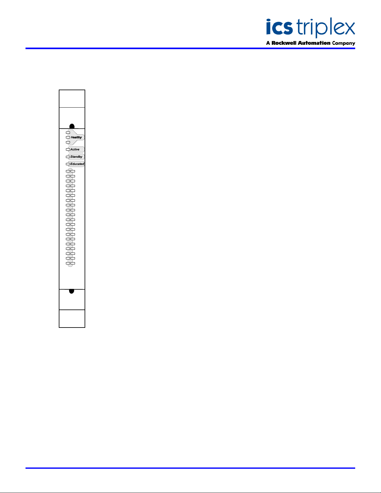
FRONT PANEL
1
2
3
4
5
6
7
8
9
10
11
12
13
14
15
16
17
18
19
20
DESCRIPTION
To meet the demanding requirements of
Safety Integrity Level (SIL) calculations,
final elements of a safety function such as
shutdown valves require regular testing.
The TUV approved (AK6, SIL3) Trusted
TMR Valve Monitor module, will control
any valve connected to it and test the
valve at regular intervals. It is used in
place of a normal controlling output
module where the automatic valve testing
function is required. The Valve Monitor
will perform the partial stroke tests,
monitor the results and pass on
information for display, alarm and
historical record via the application
program of the Trusted
TM
controller.
TM
Maximum test times are derived for each
valve to ensure the test can only move
the valve for a period which will not cause
disturbance to the process. This method
of partial stroke testing exercises the
entire shutdown path from safety system
logic to movement of the valve actuator.
The test verifies the ability of the valve to
perform its shutdown function.
Triple Modular redundancy (TMR) is used
to ensure fault tolerance. The system will
continue uninterrupted, safe operation in
the presence of one or more internal
discrepancies. Features typical of all
Trusted
TM
output modules are included,
such as, line monitoring, fuseless
protected outputs, 1msec sequence of
events (SOE) resolution, configurable
LED colours and field signal monitoring.
The Valve Monitor connects to 20 valves
by providing 20 control outputs and 20
monitoring inputs arranged together in
pairs. These pairs are in 5 isolated
groups with separate power feeds to
each. The outputs connect directly to the
Solenoid Operated Valve (SOV) or via an
Intrinsically Safe interface in the usual
way. Outputs can be normally energised
or de-energised, open or closed.
Feedback of valve position can be by limit
switches or an analogue position sensor.
The Valve Monitor connects to the field
circuits via a Versatile Field Termination
Assembly (VFTA). The VFTA allows the
user to link configure an appropriate
electrical loop for the control and
monitoring signals.
The signals that control valve open and
closed state, plus the requests to test, are
derived from the application program
running in the Trusted
TM
TMR Processor.
The IEC1131 Toolset uses a preconfigured function block to marshall
signals to and from the Valve Monitor.
The unique characteristics of each valve
such as test time, feedback thresholds
and alarm conditions, are also set in the
IEC 1131 Toolset and can be modified
online. Control of the testing can be
based on time of day, time interval or
manually initiated from the Valve Manager
operator interface.
The module has extensive automatic
diagnostics. Should a fault in the module
be detected, the Trusted
TM
TMR
Processor will flag the unhealthy
condition, indicating the need to replace
the module. Control continues until a
replacement (healthy) module is
available. Replacement modules can be
located in a Companion Slot next to the
faulty module or in a designated
SmartSlot with a temporary connection to
the faulty module.
Modules may be placed in any I/O slot in
a Trusted
TM
Processor Chassis or
Expander chassis. Mechanical keying
prevents insertion of the incorrect module.
FEATURES
40 TMR channels to control
and test 20 shutdown valves
Partial stroke testing
embedded in TMR safety
system
Tests valves to AK6 or SIL3
application requirements
Use with single or dual SOV’s
for maximum process
availability
No added hardware so no
increase in MTBF
spurious
Line monitoring
Automatic over-current
protection – no fuses required
Hot replaceable
Can be installed as retrofit
using existing field installation
Maximum increase to safety
integrity for minimum cost
On-board 1ms resolution
Sequence of Events reporting
Issue 3 Jan 2006
Page 2
SDS-8449
Trusted
TM
Industrial Control System
Trusted
TM
TMR 24Vdc Valve Monitor Module -T8449
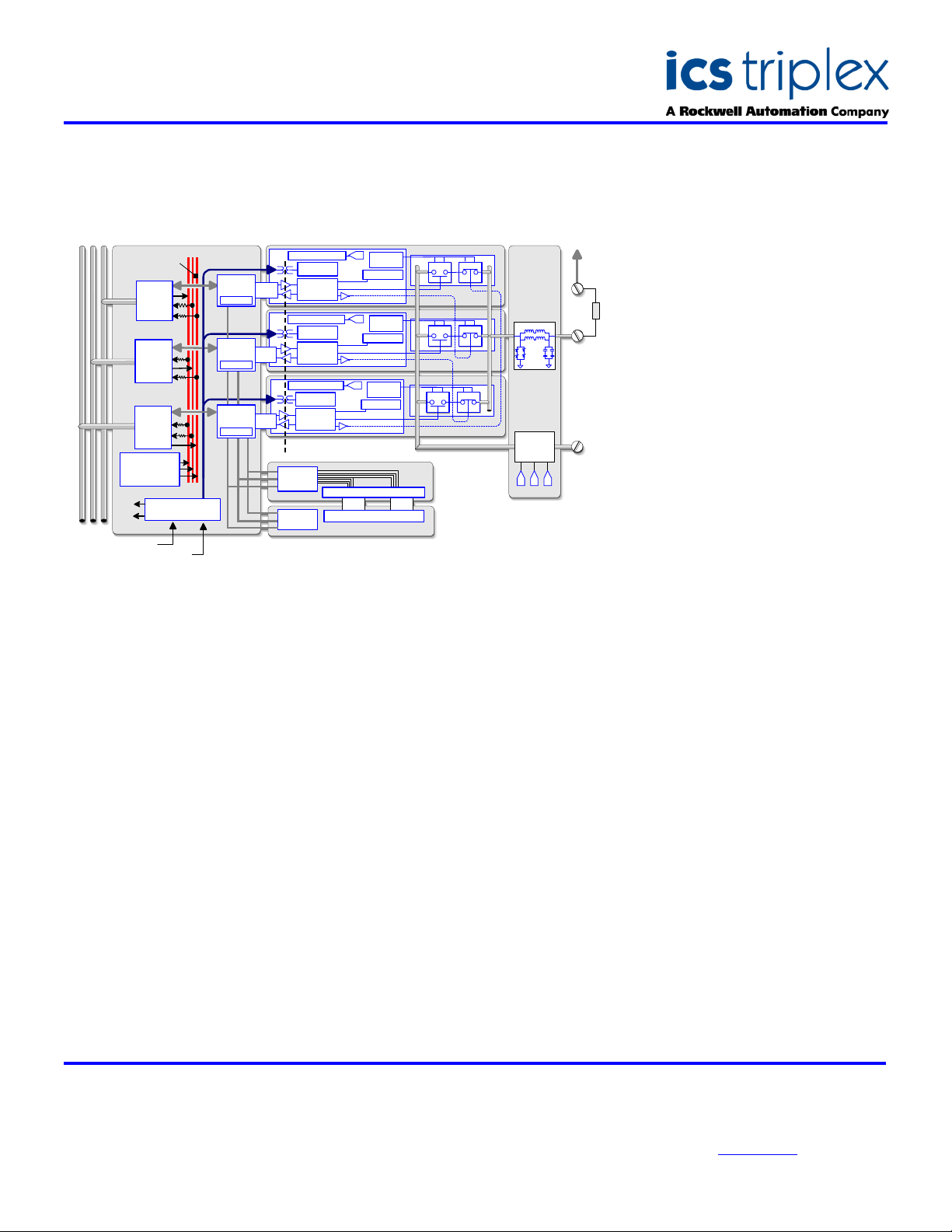
BLOCK DIAGRAM
OFIUHIU
I
nternal Voting Bus
TMR Intermodule Bus
Housekeeping
Module Temp
DSP reference
Back Plane
B
ack Plane Power Bus 1
Power Bus
Back Plane Power Bus 2
1
Bus
Interface
Bus
Interface
Bus
I
nterface
Supply Diag
Redundant Supply
S
lice
Control
ime Stamp
T
A
S
lice
Control
Time Stamp
B
Slice
Control
ime Stamp
T
B
Failsafe Bia s Control
S
lice Power
upply
S
Field Logic
Control
F
ailsafe Bias Control
S
lice Power
Supply
Field Logic
Control
F
ailsafe Bias Control
S
lice Power
Supply
Field Logic
Control
Opto Isolat ion Boundary
Front Panel
oting Logic
V
Indicators
Health
Voted Status Display LEDs
Serial Dis play Latches
F
A
D
iagnostic
onitor
M
ousekeeping
H
B
D
iagnostic
Monitor
Housekeeping
C
D
iagnostic
Monitor
Housekeeping
ront Panel
N.O.
N.O.
N.O.
FPIU
FPDU
Slice A
N
S
lice B
N.C.
Slice C
N.C.
ELECTRICAL SPECIFICATION
Number of channels
No. of Independent Power Groups
Field Common Isolation
Sustained Working ±250V dc
Maximum Withstanding ±2.5kV dc
Field Supply Voltage
Measurement Range 0 to 32V dc
Maximum Withstanding -1 to 40V dc
Output Current Rating
Continuous 2 A
Minimum 50ma
Output Off Resistance (effective
leakage)
Power Consumption at 24V (1A per
channel)
Output Turn On/Off Delay
Self-Test Interval
Output Short Circuit Protection
Fusing
Intrinsic Safety
Circuit Type
40 Channels – 20 control, 20
monitoring
5, each of 4 outputs & 4 inputs
33k>
24W
0.5ms
2 minutes
Automatic
Not required
External barrier
Fault tolerant, fully triplicated with
optional line monitoring
OFTU
.C.
F
ield Interfa ce
rotection C ircuit
P
G
roup
Fail-Safe
Switch
A B C
-
V
MECHANICAL
SPECIFICATION
Dimensions (HxWxD):
241mm x 30mm x 300mm
(9.5ins x 1.2ins x 11.8ins)
Weight:
1.13kg
(2.5lbs)
ENVIRONMENTAL
+V
Operating Temperature:
-5°C to 60°C
(23°F to 140°F)
Operating Humidity:
5 to 95%, noncondensing
Vibration:
10 to 57Hz ±0.075mm
57 to 150Hz 1.0g
Shock:
15g, ½ sine wave, 11ms
EMI (IEC 801):
ESD
Air discharge to 15kV
Contact discharge to 8kV
Radiated Fields
10V/m, 27MHz to
500MHz
Transients and Bursts
2kV, 2.5kHz for
t=60 seconds
ICS Triplex
Technical data sheets are intended for
information and guidance. The Company
has a policy of continual product
development and improvement.
Specifications are subject to change
without notice. For latest information, visit
our Websi te:- www.icstr iple x.com
 Loading...