

Page 1
SDS-8402
T8402 Trusted Dual 24
Trusted
TM
Industrial Control System
TrustedTM Dual 24Vdc Digital Input Module-T8402
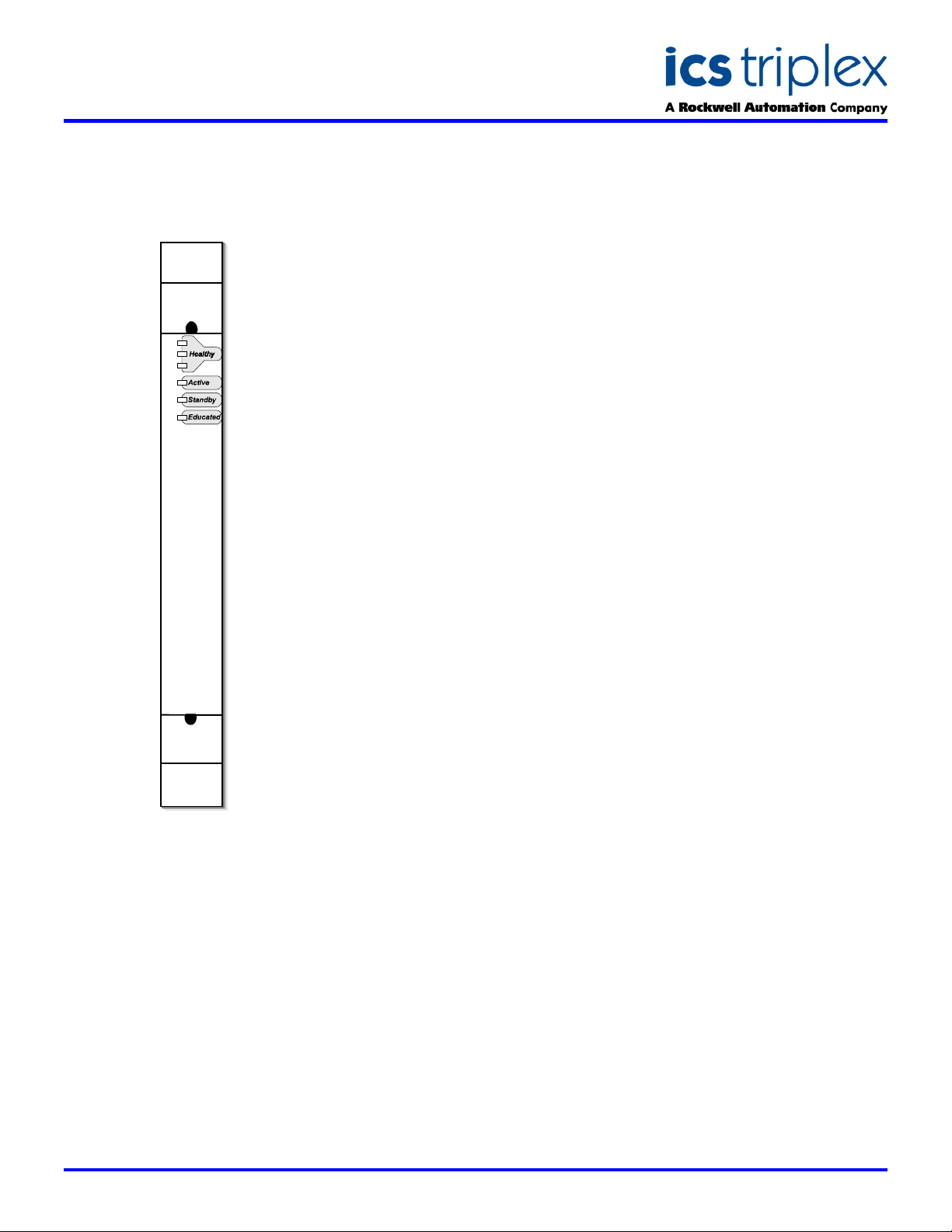
FRONT PANEL
Vdc Digital Input
DESCRIPTION
The Trusted
Input Module interfaces to 60 field
input devices. A wide input voltage
range and programmable thresholds
allow the module to be used in
current source and current sink
configurations. Comprehensive
diagnostic tests are performed on
each input channel, including tests for
stuck on and stuck off failures. Fault
tolerance is achieved through Dual
Redundancy within the same module
for each of the 60 input channels.
TM
Dual 24V dc Digital
When a line-monitoring device is
installed at the field switch, the
module can detect open and shorted
field cables. Line monitoring can be
independently configured for each
input channel.
The module provides on-board
Sequence of Events (SOE) reporting
with a resolution of 1ms. A change of
state triggers an SOE entry. States
are determined by programmable
voltage thresholds that can be
configured on a per channel basis.
When the field voltage and field return
are connected to the auxiliary input
channels of the module, thresholds
can be specified as a ratio of the
current field supply voltage.
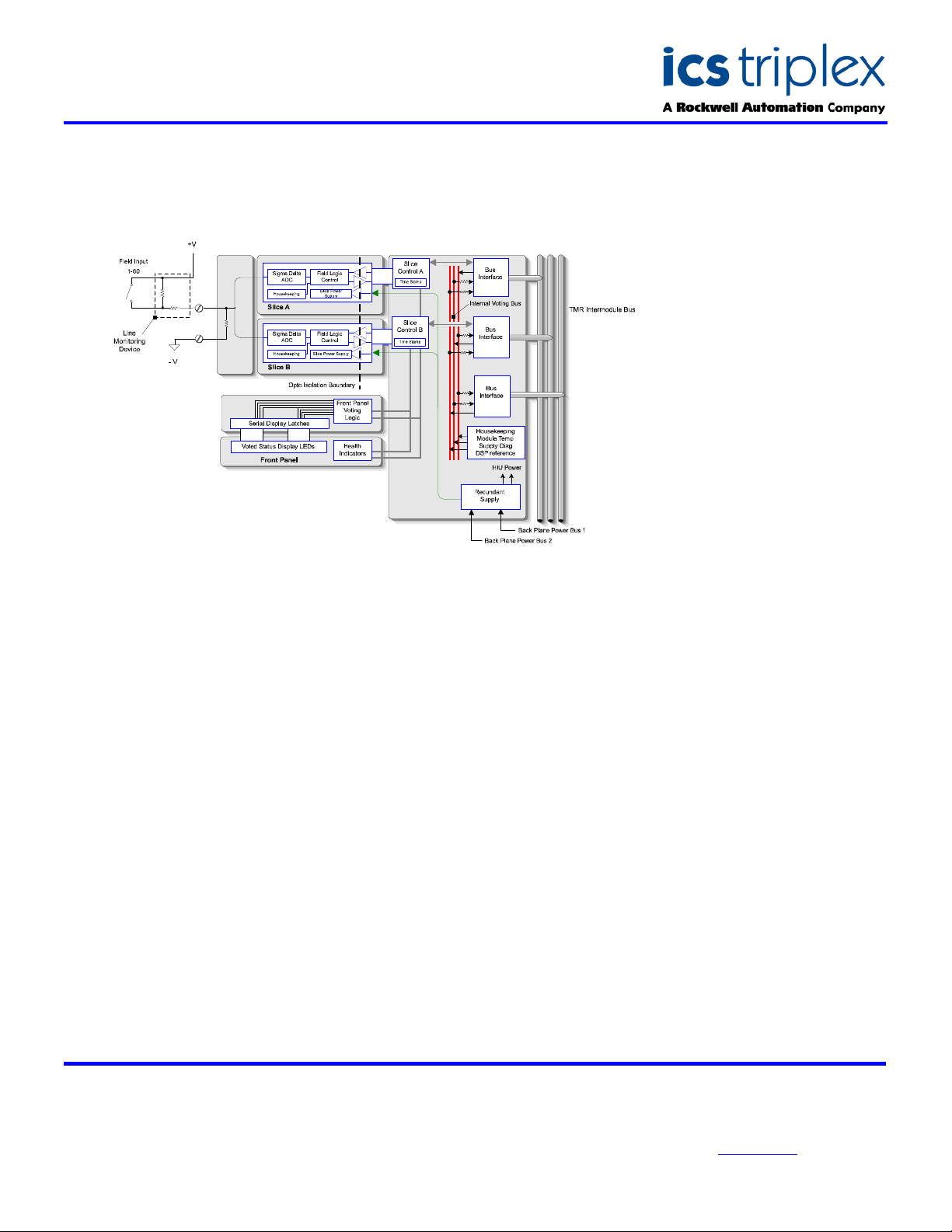
Each section of the module, referred
to as a slice, conditions and
measures each channel
independently. Each slice is optoisolated up to 2500V dc. Each slice
sends its data to a safety layer
hardware voter that presents the
information from both slices to the
Trusted
fault is detected on any dual input
channel, the Trusted
Processor will flag the error,
indicating the need to replace the
module. The Trusted
Processor will continue to use the
information provided by the remaining
slice until a replacement module is
available. Replacement modules can
be located in a standby slot next to
the module or in a designated
SmartSlot with a temporary
connection to the same Trusted
Termination Assembly.
Modules may be placed in any I/O
module slot in a Trusted
Chassis or Expander Chassis. Once
the I/O module configuration is set,
mechanical keying is available on all
I/O modules to prevent inserting a
module into an incorrect slot.
TM
TMR Processor. When a
TM
TM
TM
Processor
TMR
TMR
TM
Configuration of the module is carried
out using the Trusted
running on an Engineering
Workstation. Once configured and
loaded into the Trusted
replacement modules are on-line
educated by the TMR Processor.
TM
Toolset
TM
Controller,
FEATURES
60 Dual (1oo2D) input channels
per module
Comprehensive diagnostics
and self-test
Line monitoring on a per
channel basis
2500V dc Opto-Isolation
On-board 1ms resolution
Sequence of Events reporting
Hot replaceable
Module fault and status
indicators
IEC 61508, SIL 3 safety
applications
Issue 5 Jan 2006
Page 2
SDS-8402
Trusted
TM
Industrial Control System
TrustedTM Dual 24Vdc Digital Input Module-T8402
BLOCK DIAGRAM
ELECTRICAL SPECIFICATION
Number of Inputs
Field Common Isolation
Sustained Working ±250V dc
Maximum Withstanding ±2.5kV dc
Input Voltage
Measurement Range ±40V dc
Maximum Withstanding ±100V dc
Channel Input Resistance
Power Consumption
Sample Update Interval (no filter)
Self-Test Interval
Sequence of Events
Event Resolution 1ms
Time-stamp Accuracy ±0.5ms
Turn-on/off Voltage
Fusing
Intrinsic Safety
Circuit Type
60 Channels
5k9
12 to 15W
5ms
20s
Configurable
None, external if required
External barrier
Fault tolerant, 1-oo-2D with optional line
monitoring
MECHANICAL
SPECIFICATION
Dimensions (HxWxD):
241mm x 30mm x 300mm
(9.5ins x 1.2ins x 11.8ins)
Weight:
1.13kg
(2.5lbs)
ENVIRONMENTAL
Operating Temperature:
-5°C to 60°C
(23°F to 140°F)
Operating Humidity:
5 to 95%, noncondensing
Vibration:
10 to 57Hz ±0.075mm
57 to 150Hz 1.0g
Shock:
15g, ½ sine wave, 11ms
EMI (IEC 801):
ESD
Air discharge to 15kV
Contact discharge to 8kV
Radiated Fields
10V/m, 27MHz to
500MHz
Transients and Bursts
2kV, 2.5kHz for
t=60 seconds
ICS Triplex
Technical data sheets are intended for
information and guidance. The Company
has a policy of continual product
development and improvement.
Specifications are subject to change
without notice. For latest information, visit
our Websi te:- www.icstr iplex.com
 Loading...