

Page 1

Trusted
TM
PD-T8314
Introduction
Trusted
TM
Fibre TX/RX Unit
The TrustedTM Fibre TX/RX Unit T8314 is designed to extend the TrustedTM Expander Bus over
distances of up to 10km. This enables a Trusted
Trusted
Note: It is recommended that if a remote Expander Chassis is to be located more than 2km from the
The Expander Bus is extended by means of a communications link using a single mode fibre-optic
cable. The Trusted
Bus to a fibre-optic signal for transmission via the single mode cable. Three totally independent pairs
of Trusted
TM
system.
Controller Chassis, the route of the cable is surveyed.
M
T
Fibre TX/RX Unit converts the differential signals of the copper-based Expander
TM
Fibre TX/RX Units provide a non-interfering ‘Grey Channel’ approach to safety.
Features
• Dual 24V dc diode ORed power supply.
• Easy installation (Din rail mounting).
• Communications over a distance of 10km.
• Independent units therefore easily maintained.
• SC type connectors to two fibres (Tx & Rx).
• Low power consumption.
M
T
Expander Chassis to be located remotely from the
Issue 10 Sep 08 PD-T8314 1
Page 2

Trusted
Issue Record
Issue
Number Date Revised by Technical CheckAuthorised by Modification
7 Sep 05 J W Clark Format
8 Dec 06 N Owens I Vince P Stock Corrections
9 Nov 07 N Owens I Vince P Stock Optical Tx/Rx power
10 Sep 08 N Owens A Holgate P Stock Max length difference
TM
Fibre TX RX Unit T8314
specifications
Issue 10 Sep 08 PD-T8314 2
Page 3
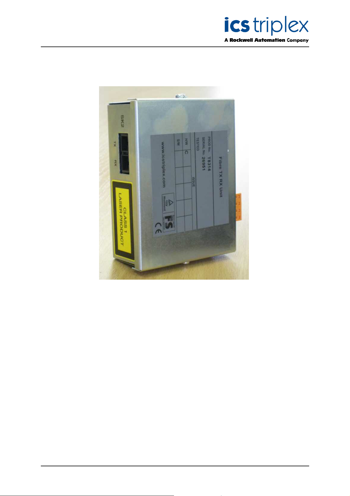
Trusted
TM
Fibre TX RX Unit T8314
Figure 1 T8314 Photo
Issue 10 Sep 08 PD-T8314 3
Page 4

Trusted
TM
Fibre TX RX Unit T8314
Table of Contents
1. Description......................................................................................................................................7
2. Installation ......................................................................................................................................9
M
3. Associated Trusted
T
Cable Selection...........................................................................................9
4. Cable Specification.......................................................................................................................10
5. Pin connections ............................................................................................................................11
5.1. Power Connection Details..........................................................................................................11
5.2. Expander Bus Connection Details .............................................................................................11
6. Specifications ...............................................................................................................................12
Figures
Figure 1 T8314 Photo ...............................................................................................................................3
M
Figure 2 Trusted
Figure 3 TrustedTM Fibre TX/RX Unit Configuration .................................................................................8
T
Fibre TX/RX Unit Block Diagram ...............................................................................7
Tabl es
M
Table 1 Associated Trusted
Table 2 Cable Specification ....................................................................................................................10
Table 3 Power Connection Details .........................................................................................................11
Table 4 Expander Bus Connection Details .............................................................................................11
T
Cable Selection ........................................................................................9
Issue 10 Sep 08 PD-T8314 4
Page 5

Trusted
TM
Fibre TX RX Unit T8314
Notice
The content of this document is confidential to ICS Triplex Technology Ltd. companies and their
partners. It may not be given away, lent, resold, hired out or made available to a third party for any
purpose without the written consent of ICS Triplex Technology Ltd.
This document contains proprietary information that is protected by copyright. All rights are reserved.
Microsoft, Windows, Windows 95, Windows NT, Windows 2000, and Windows XP are registered
trademarks of Microsoft Corporation.
The information contained in this document is subject to change without notice. The reader should, in
all cases, consult ICS Triplex Technology Ltd. to determine whether any such changes have been
made. From time to time, amendments to this document will be made as necessary and will be
distributed by ICS Triplex Technology Ltd.
Information in this documentation set may be subject to change without notice and does not represent
a commitment on the part of ICS Triplex Technology Ltd.
The contents of this document, which may also include the loan of software tools, are subject to the
confidentiality and other clause(s) within the Integrator Agreement and Software License Agreement.
No part of this documentation may be reproduced or transmitted in any form or by any means,
electronic or mechanical, including photocopying and recording, for any purpose, without the express
written permission of ICS Triplex Technology Ltd.
Disclaimer
The illustrations, figures, charts, and layout examples in this manual are intended solely to illustrate the
text of this manual.
The user of, and those responsible for applying this equipment, must satisfy themselves as to the
acceptability of each application and use of this equipment.
This document is based on information available at the time of its publication. While efforts have been
made to be accurate, the information contained herein does not purport to cover all details or variations
in hardware or software, nor to provide for every possible contingency in connection with installation,
operation, or maintenance. Features may be described herein which are present in all hardware or
software systems. ICS Triplex Technology Ltd. assumes no obligation of notice to holders of this
document with respect to changes subsequently made.
ICS Triplex Technology Ltd. makes no representation or warranty, expressed, implied, or statutory with
respect to, and assumes no responsibility for the accuracy, completeness, sufficiency, or usefulness of
the information contained herein. No warranties of merchantability or fitness for purpose shall apply.
Issue 10 Sep 08 PD-T8314 5
Page 6

Trusted
TM
Fibre TX RX Unit T8314
Revision and Updating Policy
All new and revised information pertinent to this document shall be issued by ICS Triplex Technology
Ltd. and shall be incorporated into this document in accordance with the enclosed instructions. The
change is to be recorded on the Amendment Record of this document.
Precautionary Information
WARNING
Warning notices call attention to the use of materials, processes, methods, procedures or limits which
must be followed precisely to avoid personal injury or death.
CAUTION
Caution notices call attention to methods and procedures which must be followed to avoid damage to
the equipment.
Notes:
Notes highlight procedures and contain information to assist the user in the understanding of the
information contained in this document
Warning
RADIO FREQUENCY INTERFERENCE
Most electronic equipment is influenced by Radio Frequency Interference (RFI). Caution should be
exercised with regard to the use of portable communications equipment around such equipment.
Signs should be posted in the vicinity of the equipment cautioning against the use of portable
communications equipment.
MAINTENANCE
Maintenance must be performed only by qualified personnel, otherwise personal injury or death, or
damage to the system may be caused.
Caution
HANDLING
Under no circumstances should the module housing be removed.
Associated Documents
Product Descriptions (PD) provide product specific information.
The Safety Manual contains the recommended safety requirements for the safety system design.
The PD8082B – Toolset Suite provides specific guidance on system configuration and application
generation.
The Operator and Maintenance Manual contains general guidelines on maintenance and diagnostic
procedures.
For technical support email: support@icstriplex.com
Issue 10 Sep 08 PD-T8314 6
Page 7

Trusted
TM
Fibre TX RX Unit T8314
1. Description
M
The Trusted
cabinet/bay containing the Trusted
in Figure 2 below:
T
Fibre TX/RX Unit T8314 is designed to be DIN rail mounted in the rear area of a
TM
Controller Chassis T8100. A block diagram of the Unit is shown
Figure 2 Trusted
The Unit provides a communications connection interface between the Trusted
TM
Fibre TX/RX Unit Block Diagram
TM
Controller Chassis
and a remote Expander Chassis.
TM
The Positive Emitter Coupled Logic (PECL) signal from the Trusted
the Controller Chassis is connected to the Unit by a Trusted
TM
Expander Cable TC-302. The signal is
Expander Interface Module in
fed through an isolator, then filtered and terminated before being connected to the PECL input of the
fibre-optic transceiver. The fibre-optic signal is transmitted to a similar Unit at the remote end via a
Single Mode Fibre-Optic Cable. The fibre-optic transceiver at the remote end of the link converts the
signal back to a PECL signal before transmitting it to the Trusted
filter/termination circuit, isolator and ‘F’ filter. Signals originating from the Trusted
TM
Expander Processor Module via a
TM
Expander
Processor Module in the remote Expander Chassis are processed in the same manner.
Issue 10 Sep 08 PD-T8314 7
Page 8

Trusted
Figure 3 below shows the configuration of the Unit within a Trusted
TM
Fibre TX RX Unit T8314
TM
System using a remote Expander
Chassis.
TM
Figure 3 Trusted
Fibre TX/RX Unit Configuration
Six Units and six fibres are required for each remote link with three located at each end. A dual 24V dc
power philosophy is employed allowing the user to supply each Unit with dual power feeds.
Individual Units require no configuration prior to installation within a remote communications link. Each
Unit operates in a stand-alone mode allowing replacement without interrupting the operation of the
Trusted
M
T
System.
There are no diagnostics available, but the quality of communications may be checked by using the
Expander Interface and Processor diagnostics via the application program.
Note: Data is transmitted along the dual fibre-optic link at a rate of 250MHz. Signal skew will take
place but it must not exceed 80ns, which equates to a cable length difference of 15 metres.
This requires that synchronisation must take place at the start and end of each transmission.
Skew not exceeding 80ns can be guaranteed for distances up to 2km. For distances greater
than 2km, cable routes must be surveyed to ensure that the propagation time difference
between the shortest and longest distance of the three links is less than 80ns.
Issue 10 Sep 08 PD-T8314 8
Page 9

Trusted
TM
Fibre TX RX Unit T8314
2. Installation
M
The Trusted
horizontal or vertical position as required.
Note: Allow a minimum of 200mm on either side of the Unit to allow for the fibre cable bend radius.
T
Fibre TX/RX Unit T8314 may be mounted on either of the TS32 or TS35 DIN rails in the
This bend radius may vary depending upon the type of cable chosen by the user.
3. Associated TrustedTM Cable Selection
Cable Type Description
TC-302-01 250 Mbits/s Remote Expander Outgoing Cable from T8312 to T8314
TC-303-01 250 Mbits/s Remote Expander Incoming Cable from T8314 to T8310
Table 1 Associated TrustedTM Cable Selection
Note: ICS Triplex recommends that BICC Brand-Rex Helios Optical Single Mode Fibre Cable be
used to inter-connect the Trusted
‘SC’ type connectors.
TM
Fibre TX/RX Units. The cable must be configured using
Issue 10 Sep 08 PD-T8314 9
Page 10

Trusted
TM
Fibre TX RX Unit T8314
4. Cable Specification
The specification of cables used to inter-connect Trusted
M
T
Fibre TX/RX Units is detailed below.
Parameter Value Min Max Unit
Cable type Single Mode 1300 nm
Attenuation @ 1300nm 0.38 dB/km
Cut-off Wavelength 1270 1360 nm
Dispersion @ 1300nm 3.5 nm
Bandwidth 600 MHz
Spectral Width 2.5 nm
Variation in Refractive
Index
Transmitter power
( into the fibre cable )
Receive sensitivity
( minimum power budget
for optical link )
Laser Output Optical Eye
Opening
Connector Type SC
Cores 6
0.5 %
-15 dBm
-28 dBm
Compliant With
TR-NWT-000253 and ITU-T
Recommendations G.957
Table 2 Cable Specification
Issue 10 Sep 08 PD-T8314 10
Page 11

Trusted
TM
Fibre TX RX Unit T8314
5. Pin connections
5.1. Power Connection Details
Pin Service
1 +24V dc 1
2 0V1
3 0V2
4 +24V dc 2
Table 3 Power Connection Details
Note: The 24V dc supplies are diode ORed to allow the Unit to be powered from a dual or single
source as required.
5.2. Expander Bus Connection Details
Pin Service
1 TX+
2 TX-
3 RX-
4 RX+
Table 4 Expander Bus Connection Details
Issue 10 Sep 08 PD-T8314 11
Page 12

Trusted
TM
Fibre TX RX Unit T8314
6. Specifications
Voltage Range
Power Consumption (Max)
Transmitter power
Receiver sensitivity
Maximum propagation time difference
Maximum fibre length difference
Operating Temperature
Non-operating Temperature
Operating Humidity
Environmental Specifications
Dimensions
Width
Depth
Weight
Height
18 to 32V dc
1.7W
-15 dBm minimum
-28 dBm
80ns
15m
-5°C to 60°C (23°F to 140°F)
-25°C to 70ºC (-25°F to 158°F)
5 to 95% RH
Refer to Document 552517
84mm (3.3ins)
110mm (4.3ins)
40mm (1.6ins)
320g (0.7lbs.)
Issue 10 Sep 08 PD-T8314 12
Page 13

Trusted
TM
Fibre TX RX Unit T8314
This page is intentionally blank
Issue 10 Sep 08 PD-T8314 13
Page 14

 Loading...