

Page 1

Trusted
TM
PD-T8312
Introduction
Trusted
TM
Expander Interface
Adaptor Unit
This document provides general information for the TrustedTM Expander Interface Adaptor Unit T8312.
Two versions of the Unit are available; one providing inter-connection between the Trusted
Interface Modules in the Controller Chassis and four Expander Chassis (T8312-4), and the other
providing inter-connection to seven Expander Chassis (T8312-7).
Features
• Allows easy inter-connection of Controller and Expander Chassis.
• Unit is fully shielded for EMC.
M
T
• Version available for smaller Trusted
Chassis.
• Locking connectors for increased reliability.
Systems – up to four Expander
TM
Expander
Issue 10 Jun 08 PD-T8312 1
Page 2

Trusted
Issue Record
ssue
I
Number Date Revised by Technical CheckAuthorised by Modification
9 Sep 05 J W Clark Format
10 Jun 08 N Owens A Holgate P Stock Legend and photos
TM
Expander Interface Adaptor T8312
Issue 10 Jun 08 PD-T8312 2
Page 3
Trusted
TM
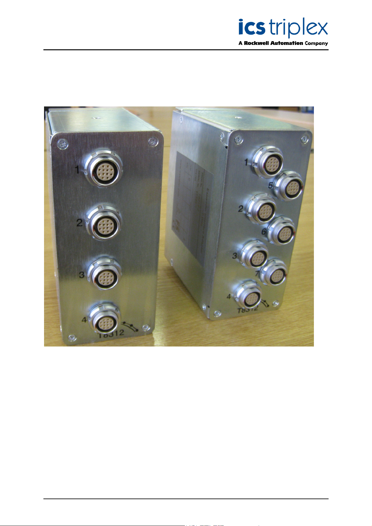
Expander Interface Adaptor T8312
Figure 1 T8312 Photo
Issue 10 Jun 08 PD-T8312 3
Page 4

Trusted
TM
Expander Interface Adaptor T8312
Table of Contents
1. Description......................................................................................................................................7
1.1. Chassis Connector (SK1) ............................................................................................................8
2. Specifications ...............................................................................................................................10
Figures
Figure 1 T8312 Photo ...............................................................................................................................3
Figure 2 Expander Interface Adaptor Schematic......................................................................................7
Tab l es
Table 1 ODU Connector Pin Assignments ...............................................................................................7
Table 2 Chassis Connector (SK1) Pinout .................................................................................................8
Issue 10 Jun 08 PD-T8312 4
Page 5

Trusted
TM
Expander Interface Adaptor T8312
Notice
The content of this document is confidential to ICS Triplex Technology Ltd. companies and their
partners. It may not be given away, lent, resold, hired out or made available to a third party for any
purpose without the written consent of ICS Triplex Technology Ltd.
This document contains proprietary information that is protected by copyright. All rights are reserved.
icrosoft, Windows, Windows 95, Windows NT, Windows 2000, and Windows XP are registered
M
trademarks of Microsoft Corporation.
The information contained in this document is subject to change without notice. The reader should, in
all cases, consult ICS Triplex Technology Ltd. to determine whether any such changes have been
made. From time to time, amendments to this document will be made as necessary and will be
distributed by ICS Triplex Technology Ltd.
Information in this documentation set may be subject to change without notice and does not represent
a commitment on the part of ICS Triplex Technology Ltd.
The contents of this document, which may also include the loan of software tools, are subject to the
confidentiality and other clause(s) within the Integrator Agreement and Software License Agreement.
No part of this documentation may be reproduced or transmitted in any form or by any means,
electronic or mechanical, including photocopying and recording, for any purpose, without the express
written permission of ICS Triplex Technology Ltd.
Disclaimer
The illustrations, figures, charts, and layout examples in this manual are intended solely to illustrate the
text of this manual.
The user of, and those responsible for applying this equipment, must satisfy themselves as to the
acceptability of each application and use of this equipment.
This document is based on information available at the time of its publication. While efforts have been
made to be accurate, the information contained herein does not purport to cover all details or variations
in hardware or software, nor to provide for every possible contingency in connection with installation,
operation, or maintenance. Features may be described herein which are present in all hardware or
software systems. ICS Triplex Technology Ltd. assumes no obligation of notice to holders of this
document with respect to changes subsequently made.
ICS Triplex Technology Ltd. makes no representation or warranty, expressed, implied, or statutory with
respect to, and assumes no responsibility for the accuracy, completeness, sufficiency, or usefulness of
the information contained herein. No warranties of merchantability or fitness for purpose shall apply.
Issue 10 Jun 08 PD-T8312 5
Page 6

Trusted
TM
Expander Interface Adaptor T8312
Revision and Updating Policy
All new and revised information pertinent to this document shall be issued by ICS Triplex Technology
Ltd. and shall be incorporated into this document in accordance with the enclosed instructions. The
change is to be recorded on the Amendment Record of this document.
Precautionary Information
WARNING
Warning notices call attention to the use of materials, processes, methods, procedures or limits which
must be followed precisely to avoid personal injury or death.
CAUTION
Caution notices call attention to methods and procedures which must be followed to avoid damage to
the equipment.
Notes:
Notes highlight procedures and contain information to assist the user in the understanding of the
information contained in this document
Warning
RADIO FREQUENCY INTERFERENCE
Most electronic equipment is influenced by Radio Frequency Interference (RFI). Caution should be
exercised with regard to the use of portable communications equipment around such equipment.
Signs should be posted in the vicinity of the equipment cautioning against the use of portable
communications equipment.
MAINTENANCE
Maintenance must be performed only by qualified personnel, otherwise personal injury or death, or
damage to the system may be caused.
Caution
HANDLING
Under no circumstances should the module housing be removed.
Associated Documents
Product Descriptions (PD) provide product specific information.
The Safety Manual contains the recommended safety requirements for the safety system design.
The PD8082B – Toolset Suite provides specific guidance on system configuration and application
generation.
The Operator and Maintenance Manual contains general guidelines on maintenance and diagnostic
procedures.
For technical support email: support@icstriplex.com
Issue 10 Jun 08 PD-T8312 6
Page 7

Trusted
TM
Expander Interface Adaptor T8312
1. Description
The TrustedTM Expander Interface Adaptor Unit T8312 comprises four, or seven 12-pin ODU
connectors (dependent on type of unit), a printed circuit board (pcb), a 96-way C type connector which
plugs into a double 96-way connector assembly designed to be connected to the Trusted
Interface modules resident in the Controller Chassis. The Unit is contained within a metal enclosure
and is designed to be clipped onto the Controller Chassis rear connectors. A release button is
provided to enable the Unit to be disconnected.
The illustration below shows the configuration of the Unit.
M
T
Expander
Figure 2 Expander Interface Adaptor Schematic
The ODU connectors are mounted on the rear of the Unit and are numbered to identify the Expander
Chassis which may be connected. The pin assignments for the ODU connectors are as follows:
Pin Service
1 TXA+
2 TXA-
3 RXA+
4 RXA-
5 TXB+
6 TXB-
7 RXB+
8 RXB-
9 TXC+
10 TXC-
11 RXC+
12 RXC-
Table 1 ODU Connector Pin Assignments
The cable which must be used with the Unit is the 250MHz Communications Cable – TC-301-01.
Issue 10 Jun 08 PD-T8312 7
Page 8

Trusted
TM
Expander Interface Adaptor T8312
1.1. Chassis Connector (SK1)
SK1 is a double, 96-way DIN41612, C-type connector.
Pin
10 TXC3+ TXC2+ TXC1+
11 GND GND GND
12 RXB7- RXB6- RXB5-
13 RXB7+ RXB6+ RXB5+
14 RXB4- RXB3- RXB2-
15 RXB4+ RXB3+ RXB2+
16 RXB1- LB_B_ACTN/STB_1 TXB7-
17 RXB1+ LB_B_ACTN/STB_2 TXB7+
18 TXB6- TXB5- TXB4-
19 TXB6+ TXB5+ TXB4+
20 TXB3- TXB2- TXB1-
21 TXB3+ TXB2+ TXB1+
22 GND GND GND
23 RXA7- RXA6- RXA5-
24 RXA7+ RXA6+ RXA5+
25 RXA4- RXA3- RXA2-
26 RXA4+ RXA3+ RXA2+
27 RXA1- LB_C_ACTN/STB_1 TXA7-
28 RXA1+ LB_C_ACTN/STB_2 TXA7+
29 TXA6- TXA5- TXA4-
30 TXA6+ TXA5+ TXA4+
31 TXA3- TXA2- TXA1-
32 TXA3+ TXA2+ TXA1+
CONNECTOR SK1 PINOUT
A B C
1 RXC7- RXC6- RXC5-
2 RXC7+ RXC6+ RXC5+
3 RXC4- RXC3- RXC2-
4 RXC4+ RXC3+ RXC2+
5 RXC1- LB_A_ACTN/STB_1 TXC7-
6 RXC1+ LB_A_ACTN/STB_2 TXC7+
7 TXC6- TXC5- TXC4-
8 TXC6+ TXC5+ TXC4+
9 TXC3- TXC2- TXC1-
Table 2 Chassis Connector (SK1) Pinout
Issue 10 Jun 08 PD-T8312 8
Page 9

Trusted
Address 2
Address 3
Address 4
Address 5
Address 6
Address 7
Address 8
Address
5
Address
4
Address
3
Address
2
Chassis connections for both units are organised as below.
TM
Expander Interface Adaptor T8312
Chassis
Chassis
Chassis
Chassis
1 connects to the first expander chassis (which has its three ID switches configured to address 2)
2 connects to the second expander chassis (which has its three ID switches configured to address 3)
…
8 connects to the eighth expander chassis (which has its three ID switches configured to address 8)
The addresses are set 2,3,4…8 to fit logically with the processor chassis virtual address of 1. If more
than eight chassis are needed, a second expander interface is required. The address switches on
these chassis are also set 2,3,4…8 but the virtual addresses (as seen by the application and
diagnostics) are 9,10,11…15 as set in the System.INI configuration.
Chassis
Chassis
Chassis
Chassis
Chassis
Chassis
Chassis
Refer to PD-8300 for further explanations on ID settings.
Issue 10 Jun 08 PD-T8312 9
Page 10

Trusted
TM
Expander Interface Adaptor T8312
2. Specifications
Use with Chassis/Module
Expander Bus Data Rate
perating Temperature
O
Non-operating Temperature
Operating Humidity
Environmental Specifications
Dimensions
Height
Width
Depth
Weight
T8100/T8311
250Mbps (1.5Gbps)
-5ºC to 60ºC (23ºF to 140ºF)
-25ºC to 70ºC (-25ºF to 158ºF)
5 to 95% RH
Refer to Document 552517
130mm (5.1ins)
60mm (2.4ins)
115mm (4.5ins)
650gms (1.43lbs.)
Issue 10 Jun 08 PD-T8312 10
Page 11

Trusted
TM
Expander Interface Adaptor T8312
This page intentionally blank
Issue 10 Jun 08 PD-T8312 11
Page 12

 Loading...