

Page 1

Trusted
TM
Module T8310
TM
Trusted
TMR Expander Processor
Introduction
The TrustedTM TMR Expander Processor module resides in the processor slots of the TrustedTM
Expander Chassis and provides the ‘slave’ interface between the Expansion Bus and the Expander
Chassis backplane. The Expander Bus allows multiple chassis systems to be implemented using UTP
cable connections whilst maintaining the fault tolerant, high bandwidth IMB capabilities.
The module provides fault containment for the expander bus, the module itself and the expander
chassis, ensuring that the effects of these potential faults are localised and system availability
maximised. The module is fault tolerant with HIFT TMR architecture. Comprehensive diagnostics,
monitoring and testing provide rapid fault identification. Hot standby and module spare configurations
are supported, allowing automatic and manual repair strategies.
Features
• Triple Modular Redundant (TMR), fault tolerant (3-2-0) operation
• Hardware Implemented Fault Tolerant (HIFT) architecture
• Dedicated hardware and software test regimes which provide very fast
fault recognition and response times
• Automatic fault handling without nuisance alarming
• Hot replacement
• Front panel indicators that show module health and status.
Issue 12 Dec 06 PD-T8310 1
Page 2

Trusted
Issue Record
Issue
Number Date Revised by Technical CheckAuthorised by Modification
9 Oct 05 Format
10 Aug 06 N Owens I Vince P Stock Corrections
11 Nov 06 N Owens I Vince P Stock Specifications
12 Dec 06 N Owens I Vince P Stock Cable Distance
TM
Module T8310
Issue 12 Dec 06 PD-T8310 2
Page 3

Trusted
TM
Module T8310
This page is intentionally blank
Issue 12 Dec 06 PD-T8310 3
Page 4

Trusted
TM
Module T8310
Table of Contents
1. Description...................................................................................................................................8
1.1. Overview......................................................................................................................................9
1.2. Power Distribution........................................................................................................................9
2. Installation..................................................................................................................................10
2.1. Module Insertion and Removal ..................................................................................................11
2.2. Module Replacement .................................................................................................................11
2.3. Expander Bus Connection .........................................................................................................12
2.3.1. Cable Assembly Replacement...................................................................................................12
2.4. Expander Chassis IMB Connector (SK1) ..................................................................................13
2.5. Expander Chassis Bus Connector (PL4)...................................................................................14
2.6. TrustedTM Module Polarisation/Keying.......................................................................................15
3. Application .................................................................................................................................16
3.1. Message Forwarding .................................................................................................................16
3.2. Control Signal Forwarding .........................................................................................................16
3.3. Interface Module Selection ........................................................................................................16
3.4. IMB Power Generation...............................................................................................................17
3.5. IMB Clock Generation................................................................................................................17
3.6. 24V Supply Monitoring...............................................................................................................17
3.7. Module Information ....................................................................................................................17
3.8. Communication Busses .............................................................................................................18
3.8.1. Expander Bus ............................................................................................................................18
3.8.2. Inter-Module Bus........................................................................................................................18
3.9. Module Configuration.................................................................................................................18
3.10. I/O Complex Equipment Definition T8310 .................................................................................19
3.10.1. Voltage Level Format.................................................................................................................20
3.11. System Initialisation File ............................................................................................................20
4. Operation ...................................................................................................................................21
4.1. Standby......................................................................................................................................21
4.2. Active .........................................................................................................................................21
4.3. Expander Processor Module Active/standby Control.................................................................21
4.4. Front Panel ................................................................................................................................22
4.5. Module Status LEDs ..................................................................................................................23
5. Fault Finding and Maintenance..................................................................................................24
5.1. Fault Reporting ..........................................................................................................................24
5.2. Companion Slot .........................................................................................................................24
5.3. Troubleshooting.........................................................................................................................25
6. Specifications.............................................................................................................................27
Issue 12 Dec 06 PD-T8310 4
Page 5

Trusted
TM
Module T8310
Figures
Figure 1 Simplified Block Diagram ...........................................................................................................8
Figure 2 Expander Processor Slots ........................................................................................................10
Figure 3 Expander Processor Cable ......................................................................................................10
Figure 4 Module Polarisation ..................................................................................................................15
Figure 5 Module Configuration ...............................................................................................................18
Figure 6 Front Panel ...............................................................................................................................22
Tables
Table 1 IMB SK1 Pinout Connections ....................................................................................................13
Table 2 PL4 Pinout Connections ............................................................................................................14
Table 3 Module Status Indicators ...........................................................................................................23
Issue 12 Dec 06 PD-T8310 5
Page 6

Trusted
TM
Module T8310
Notice
The content of this document is confidential to ICS Triplex Technology Ltd. companies and their
partners. It may not be given away, lent, resold, hired out or made available to a third party for any
purpose without the written consent of ICS Triplex Technology Ltd.
his document contains proprietary information that is protected by copyright. All rights are reserved.
T
Microsoft, Windows, Windows 95, Windows NT, Windows 2000, and Windows XP are registered
trademarks of Microsoft Corporation.
The information contained in this document is subject to change without notice. The reader should, in
all cases, consult ICS Triplex Technology Ltd. to determine whether any such changes have been
made. From time to time, amendments to this document will be made as necessary and will be
distributed by ICS Triplex Technology Ltd.
Information in this documentation set may be subject to change without notice and does not represent
a commitment on the part of ICS Triplex Technology Ltd.
The contents of this document, which may also include the loan of software tools, are subject to the
confidentiality and other clause(s) within the Integrator Agreement and Software License Agreement.
No part of this documentation may be reproduced or transmitted in any form or by any means,
electronic or mechanical, including photocopying and recording, for any purpose, without the express
written permission of ICS Triplex Technology Ltd.
Disclaimer
The illustrations, figures, charts, and layout examples in this manual are intended solely to illustrate the
text of this manual.
The user of, and those responsible for applying this equipment, must satisfy themselves as to the
acceptability of each application and use of this equipment.
This document is based on information available at the time of its publication. While efforts have been
made to be accurate, the information contained herein does not purport to cover all details or variations
in hardware or software, nor to provide for every possible contingency in connection with installation,
operation, or maintenance. Features may be described herein which are present in all hardware or
software systems. ICS Triplex Technology Ltd. assumes no obligation of notice to holders of this
document with respect to changes subsequently made.
ICS Triplex Technology Ltd. makes no representation or warranty, expressed, implied, or statutory with
respect to, and assumes no responsibility for the accuracy, completeness, sufficiency, or usefulness of
the information contained herein. No warranties of merchantability or fitness for purpose shall apply.
Issue 12 Dec 06 PD-T8310 6
Page 7

Trusted
TM
Module T8310
Revision and Updating Policy
All new and revised information pertinent to this document shall be issued by ICS Triplex Technology
Ltd. and shall be incorporated into this document in accordance with the enclosed instructions. The
change is to be recorded on the Amendment Record of this document.
Precautionary Information
WARNING
Warning notices call attention to the use of materials, processes, methods, procedures or limits which
must be followed precisely to avoid personal injury or death.
CAUTION
Caution notices call attention to methods and procedures which must be followed to avoid damage to
the equipment.
Notes:
Notes highlight procedures and contain information to assist the user in the understanding of the
information contained in this document
Warning
RADIO FREQUENCY INTERFERENCE
Most electronic equipment is influenced by Radio Frequency Interference (RFI). Caution should be
exercised with regard to the use of portable communications equipment around such equipment.
Signs should be posted in the vicinity of the equipment cautioning against the use of portable
communications equipment.
MAINTENANCE
Maintenance must be performed only by qualified personnel, otherwise personal injury or death, or
damage to the system may be caused.
Caution
HANDLING
Under no circumstances should the module housing be removed.
Associated Documents
Product Descriptions (PD) provide product specific information.
The Safety Manual contains the recommended safety requirements for the safety system design.
The PD8082B – Toolset Suite provides specific guidance on system configuration and application
generation.
The Operator and Maintenance Manual contains general guidelines on maintenance and diagnostic
procedures.
For technical support email: support@icstriplex.com
Issue 12 Dec 06 PD-T8310 7
Page 8
Trusted
TM
Module T8310
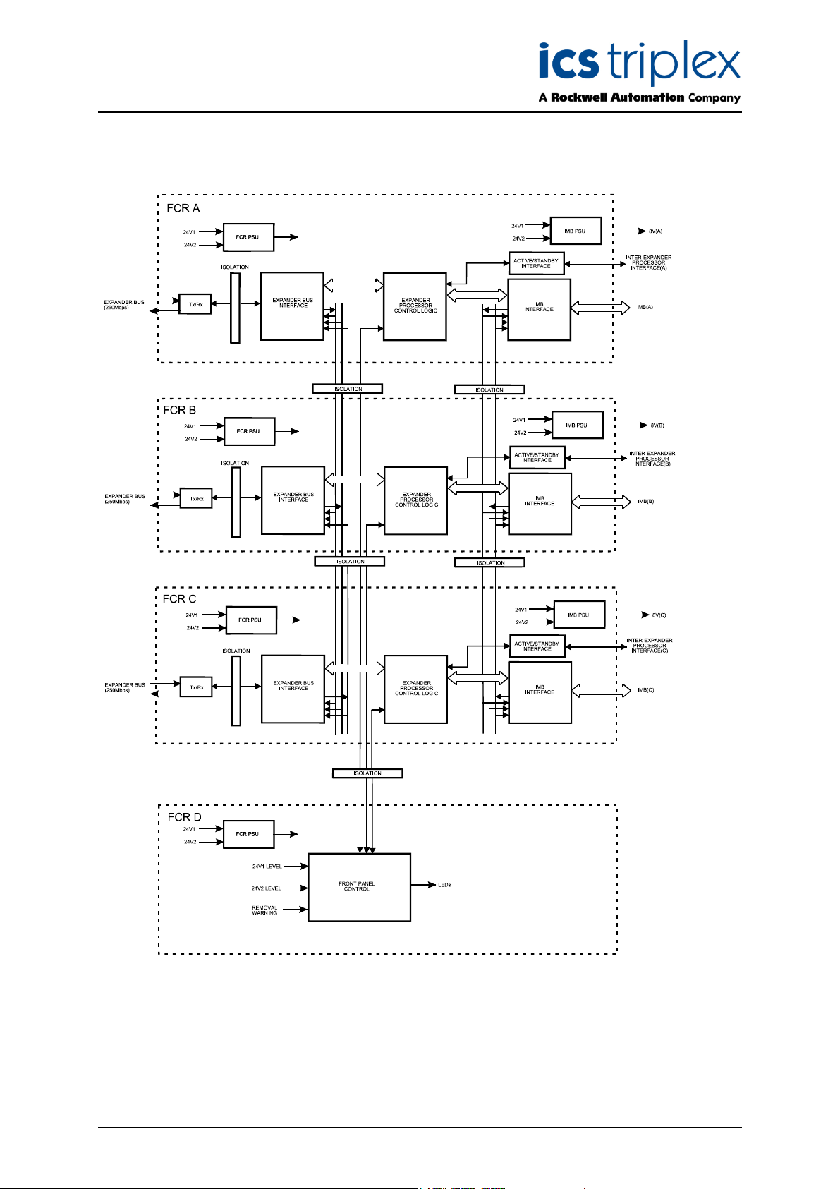
1. Description
Figure 1 Simplified Block Diagram
Issue 12 Dec 06 PD-T8310 8
Page 9

Trusted
TM
Module T8310
1.1. Overview
The TMR Expander Processor is a fault tolerant design based on TMR architecture arranged in a lockstep configuration. Figure 1 shows, in simplified terms, the basic structure of the TMR Expander
Processor.
he module has three main fault containment regions (FCR A, B and C). Each of the main FCRs
T
contains interfaces to the Expander Bus and Inter-Module Bus (IMB), an active/standby interface to the
other TMR Expander Processor in the chassis, control logic, communications transceivers and power
supplies.
Communication between the module and the TMR Processor is via the TMR Expander Interface
Module and the triplicated Expander Bus. The Expander Bus is triplicated, point-to-point architecture.
Each channel of the Expander Bus comprises separate command and response media. Voting is
provided at the Expander Bus Interface to ensure that cable faults are tolerated, and the remainder of
the Expander Processor operates in a fully triplicated mode, even in case of cable faults occurring.
Communication between the module and the I/O modules in the Expander Chassis is via the IMB on
the backplane of the Expander Chassis. The IMB is identical to that within the Controller Chassis,
providing the same fault tolerant, high bandwidth communications between the interface modules and
the TMR Processor. As with the Expander Bus Interface all transactions are voted, localising faults to
the IMB should they occur.
A fourth FCR (FCR D) provides the non-critical monitoring and display functions and is also part of the
inter-FCR Byzantine voting structure.
Isolation is provided between FCRs wherever interfaces are required, to ensure that faults can not
propagate between them.
1.2. Power Distribution
The TMR Expander Processor Module derives its internal voltages from dual redundant +24V dc
power supplied via the module connector from the Trusted
derives the required supplies independently.
TM
Expander Chassis backplane. Each FCR
Issue 12 Dec 06 PD-T8310 9
Page 10

Trusted
TM
Module T8310
2. Installation
The Expander Processor module always resides in one of the two processor (left most - PL1 and PL2)
slots within the Expander Chassis. The Expander Processor must NOT be installed in these other
module locations, as this may cause damage to the module.
Figure 2 Expander Processor Slots
The two processor slots must be interconnected using the Cable Hood Assembly shown below.
Figure 3 Expander Processor Cable
The Expander Processor Modules are connected to the Expander Interface modules by the Expander
Interface Hot Link Cable TC-301 via the Trusted
Remote Expander Processor Modules are connected to the Trusted
TM
Expander Interface Adaptor Unit T8312.
TM
Fibre Optic Tx/Rx Unit T8314 by
the Fibre Tx/Rx Unit to Expander Processor (Remote Expanders) Cable TC-303.
TM
The connection to the Trusted
Trusted
TM
Expander Interface Adaptor Unit using the Expander Interface Adaptor to Fibre Tx/Rx Unit
Fibre Optic Tx/Rx Unit from the Expander Interface Modules is via the
(Remote Expanders) Cable TC-302.
Issue 12 Dec 06 PD-T8310 10
Page 11

Trusted
TM
Module T8310
2.1. Module Insertion and Removal
CAUTION:
The module contains static sensitive parts. static handling precautions must be observed. Specifically
nsure that exposed connector pins ARE NOT TOUCHED. Under no circumstances should the
e
module housing BE REMOVED.
Before installation, visually inspect the module for damage. Ensure that the module housing appears
undamaged and inspect the I/O connector at the back of the module for bent pins. If the module
appears damaged or any pins are bent, do not install the module. Do not try to straighten bent pins.
Return the module for replacement.
Ensure that the module is of the correct type.
Record the module type, revision and serial number of the module before installation.
If the module is to reside in a new chassis, or the system is being configured for the first time, ensure
that the chassis address has been set correctly before installing the modules. See Expander Chassis
Product Description (PD-8300) for further details.
To install the module:
1. Ensure that the cable assembly is correctly located.
2. Release the ejector tabs on the module using the release key. Ensure that the ejector tabs
are fully open.
3. Holding the ejectors, carefully insert the module into the intended slot.
4. Push the module fully home by pressing on the top and bottom of the module fascia.
5. Close the module ejectors, ensuring that they click into their locked position.
2.2. Module Replacement
The replacement module must be inserted in to the vacant processor slot, ensuring that the module is
correctly located and the ejector tabs are closed (see Module Insertion ands Removal). The newly
installed module will perform its power-up sequence.
Ensure that the LED indicators on the newly installed module are as follows:
LED 1 Healthy A Steady Green
LED 2 Healthy B Steady Green
LED 3 Healthy C Steady Green
If the original module has reported faults, the TMR Processor may automatically initiate the
changeover to the newly installed module. Manual changeover may be initiated either using the ejector
tabs on the original module or using commands via the diagnostic interface. To initiate the changeover
using the ejector tabs use the following sequence:
1. Release both the top and bottom ejector tabs on the original module using the ejector release
tool. DO NOT remove the module.
2. Wait until the original module indicates that it is in the standby mode of operation and the
newly installed module is in the active mode.
3. Remove the original module.
Note: Under no circumstances remove a module that is indicating ACTIVE mode. Removal of an
active module may result in modules within the chassis adopting their default (shutdown) state,
and initiate shutdown states via the application program.
Issue 12 Dec 06 PD-T8310 11
Page 12

Trusted
In Hot-standby configurations, with both Expander Processor Modules installed, the faulted module
may be either the active or the standby module. In most cases the system will automatically switch to
the healthiest module, therefore only the standby module will require replacement. To replace the
active module follow the steps described above. To replace the standby module:
In Hot-standby configurations, the replacement module should then be installed in the position where
the previous module was removed. This module will become the standby module.
TM
Module T8310
1. Release both the top and bottom ejectors tabs on the standby module using the ejector
release tool.
2. Ensure that the other module is indicating the active mode of operation.
3. Remove the standby module.
2.3. Expander Bus Connection
Further details of the Expander Bus cable assembly are provided in the associated Product Description
PD-TC300.
2.3.1. Cable Assembly Replacement
It is not intended that the cable should need replacement, however this may be achieved by
replacement of the complete cable assembly that requires that the system be shutdown. To remove a
cable:
1. Ensure that the correct chassis and slot positions are selected.
2. Ensure the associated chassis slots are not occupied by modules.
3. Press in the hood release button and slide the hood downwards.
4. Remove the hood from the chassis slot by sliding down and rearward.
To insert a new or replacement cable:
1. Ensure that the correct chassis and slot positions are selected.
2. Ensure that the associated chassis slots are not occupied by modules.
3. Present the connector to the chassis backplate slot, taking care to align the lugs of the
connector with the cut-outs of the slot.
4. Push the connector hood in and upwards into the slot until the latch engages with the
backplate lip.
5. Ensure that the connector hood is secure in its position.
Where it is critical to maintain system operation additional chassis may be installed and on-line
operation maintained by transferred control to modules within that chassis using the I/O modules
SmartSlot capability.
Issue 12 Dec 06 PD-T8310 12
Page 13

Trusted
TM
Module T8310
2.4. Expander Chassis IMB Connector (SK1)
SK1 is a 185-way DIN41642 type connector.
CONNECTOR SK1 PINOUT
PIN E D C B A
2 CHASSIS_GND CHASSIS_GND CHASSIS_GND CHASSIS_GND CHASSIS_GND
3
4 IMB_+24V_RTN IMB_+24V_RTN IMB_+24V_RTN IMB_+24V_RTN IMB_+24V_RTN
5
6 IMB_+24V_1 IMB_+24V_1 IMB_+24V_1 IMB_+24V_1 IMB_+24V_1
7
8 IMB_+24V_2 IMB_+24V_2 IMB_+24V_2 IMB_+24V_2 IMB_+24V_2
9
10 IMBA_CHAS_ID_3 IMBA_CHAS_ID_2 IMBA_CHAS_ID_1 IMBA_CHAS_ID_0 IMBA_MN/IX_ID
11 IMBA_CMDN_RSP GND IMBA_XIM_SEL_OUTNIMBA_XIM_SEL_INN IMBA_IOM_SELN_1
12 IMBA_D0 GND IMBA_D1 IMBA_IOM_SELN_2 IMBA_IOM_SELN_3
13 IMBA_D2 GND IMBA_D3 IMBA_IOM_SELN_4 IMBA_IOM_SELN_5
14 IMBA_D4 GND IMBA_D5 IMBA_IOM_SELN_6 IMBA_IOM_SELN_7
15 IMBA_D6 GND IMBA_D7 IMBA_IOM_SELN_8 IMBA_IOM_SELN_9
16 IMBA_CK_OUT GND IMBA_XIM_CLK_IN IMBA_IOM_SELN_10IMBA_IOM_SELN_11
17 IMBA_IOM_CK1 GND IMBA_SFTY_WDOG IMBA_IOM_SELN_12
18 IMBA_IOM_CK2 GND IMBA_PWR_FAIL IMBA_+6.5V
19 IMBB_CHAS_ID_3 IMBB_CHAS_ID_2 IMBB_CHAS_ID_1 IMBB_CHAS_ID_0 IMBB_MN/IX_ID
20 IMBB_CMDN_RSP GND IMBB_XIM_SEL
OUTN
21 IMBB_D0 GND IMBB_D1 IMBB_IOM_SELN_2 IMBB_IOM_SELN_3
22 IMBB_D2 GND IMBB_D3 IMBB_IOM_SELN_4 IMBB_IOM_SELN_5
23 IMBB_D4 GND IMBB_D5 IMBB_IOM_SELN_6 IMBB_IOM_SELN_7
24 IMBB_D6 GND IMBB_D7 IMBB_IOM_SELN_8 IMBB_IOM_SELN_9
25 IMBB_CK_OUT GND IMBB_XIM_CLK_IN IMBB_IOM_SELN_10IMBB_IOM_SELN_11
26 IMBB_IOM_CK1 GND IMBB_SFTY_WDOG IMBB_IOM_SELN_12
27 IMBB_IOM_CK2 GND IMBB_PWR_FAIL IMBB_+6.5V
28 IMBC_CHAS_ID_3 IMBC_CHAS_ID_2 IMBC_CHAS_ID_1 IMBC_CHAS_ID_0 IMBC_MN/IX_ID
29 IMBC_CMDN_RSP GND IMBC_XIM_SEL_OU
TN
30 IMBC_D0 GND IMBC_D1 IMBC_XIM_SELN_2 IMBC_IOM_SELN_3
31 IMBC_D2 GND IMBC_D3 IMBC_XIM_SELN_4 IMBC_IOM_SELN_5
32 IMBC_D4 GND IMBC_D5 IMBC_XIM_SELN_6 IMBC_IOM_SELN_7
33 IMBC_D6 GND IMBC_D7 IMBC_XIM_SELN_8 IMBC_IOM_SELN_9
34 IMBC_CK_OUT GND IMBC_XIM_CLK_IN IMBC_XIM_SELN_10 IMBC_IOM_SELN_11
35 IMBC_IOM_CK1 GND IMBC_SFTY_WDOG IMBC_IOM_SELN_12
36 IMBC_IOM_CK2 GND IMBC_PWR_FAIL IMBC_+6.5V
37
38 CHASSIS_GND CHASSIS_GND CHASSIS_GND CHASSIS_GND CHASSIS_GND
IMBB_XIM_SEL_INN IMBB_IOM_SELN_1
IMBC_XIM_SEL_INN IMBC_IOM_SELN_1
Table 1 IMB SK1 Pinout Connections
Issue 12 Dec 06 PD-T8310 13
Page 14

Trusted
TM
Module T8310
2.5. Expander Chassis Bus Connector (PL4)
PL4 is a 96-way DIN41612, C-type connector.
Pin
10
11 GND GND GND
12 TXB+
13 TXB-
14
15
16 RXB1+ LB_B_ACTN/STB_OUT
17 RXB1- LB_B_ACTN/STB_IN
18
19
20
21
22
23 TXC+
24 TXC-
25
26
27 RXC1+ LB_C_ACTN/STB_OUT
28 RXC1- LB_C_ACTN/STB_IN
29
30
31
32
CONNECTOR PL4 PINOUT
A B C
1 TXA+
2 TXA-
3
4
5 RXA1+ LB_A_ACTN/STB_OUT
6 RXA1- LB_A_ACTN/STB_IN
7
8
9
Table 2 PL4 Pinout Connections
Issue 12 Dec 06 PD-T8310 14
Page 15

Trusted
TM
Module T8310
2.6. TrustedTM Module Polarisation/Keying
M
All Trusted
The polarisation comprises two parts. The module and the associated field cable.
ach module type has been keyed during manufacture. The organisation responsible for the
E
integration of the Trusted
so that they correspond with the bungs fitted to the associated module prior to fitting.
T
Modules have been Keyed to prevent insertion into the wrong position within a chassis.
TM
system must key the cable by removing the keying pieces from the cable
Cable Exit
1
Polarising/Keying
Pins.
(Remove using
side cutters
where identified
TrustedTM
Cable hood
below)
12
Release button
Figure 4 Module Polarisation
For Cables with Companion slot installations both keying strips must be polarised.
For This Module (T8310) remove keying pins 1,2,5.
Smart
Swap
Connect
or if
Fitted
Issue 12 Dec 06 PD-T8310 15
Page 16

Trusted
TM
Module T8310
3. Application
3.1. Message Forwarding
The primary function of the Expander is to provide a method of extending the IMB beyond a single
processor chassis. The active TMR Expander Interface Module receives messages from the
processor chassis IMB/backplane and forwards them to the Expander Bus when its slot position is
enabled. Similarly, the active TMR Expander Processor Module forwards all messages received from
the Expander Bus to the Expander Chassis IMB.
Messages addressed to the Expander Processor module itself, i.e. those command messages with
chassis and slot address fields matching those of the module, result in the message being handled
locally and the appropriate response message being generated. For other command messages the
response message received by the active Expander Processor from the addressed module is passed
to the Expander Bus and hence to the TMR Expander Interface Module. The active TMR Expander
Interface Module then passes the message to the Processor Chassis IMB, subject to the prevailing
IMB control signals.
The messages received from the controller chassis IMB at the TMR Expander Interface Module are
re-synchronised and majority voted before being passed to the triplicated Expander Bus. Similarly,
messages received by the TMR Expander Processor Module from the Expander Chassis IMB are
re-synchronised and majority voted before onward transmission.
Messages received from the Expander Bus at both the TMR Expander Interface Module and TMR
Expander Processor Module are re-synchronised and majority voted (Byzantine voted) before being
passed to the associated IMB.
Errors in messages are corrected, and therefore masked using this method. This, however, makes it
important that discrepancies in faults in these signals are detected and the information made available
for fault reporting purposes to avoid latent fault issues.
3.2. Control Signal Forwarding
The active TMR Expander Interface Module continually monitors and transmits the state of the
following signals:
• Power Failure Warning
• System Watchdog
• Command Response Control
All three signals are fully triplicated. These signals are distributed to all of the attached Expander
Busses. The TMR Expander Processor Modules forward the received state of these signals to the
Expander Chassis IMB. The direction of these signals is always from TMR Processor to TMR
Expander Interface to TMR Expander Processor to interface (I/O) module.
As with the message forwarding, these signals are re-synchronised and majority voted, i.e. Byzantine
voted at the TMR Expander Interface and TMR Expander Processor Modules. The signals are
synchronous within the Expander Chassis even in the case of a fault within the Processor Chassis.
3.3. Interface Module Selection
The active TMR Expander Processor Module monitors the received command messages and decodes
chassis and slot information where the message’s chassis number matches that set by the local
switches.
Issue 12 Dec 06 PD-T8310 16
Page 17

Trusted
Expander Bus link quality, including receive error counts for each communications link and link
TM
Module T8310
3.4. IMB Power Generation
The TMR Expander Processor Modules (both active and standby) generate three independent IMB
power supplies. These supplies are provided via a diode to the IMB/backplane. These supplies are
used to power the triplicated IMB interfaces within the interface modules within the Expander Chassis.
These supplies have a common return, commoned with the module’s internal 0V. Failure of any of
these supplies will not affect the remaining supplies. Similarly, overload conditions on a supply will not
affect the continued operation of the other supplies.
3.5. IMB Clock Generation
The active TMR Expander Processor Module provides synchronised IMB clock signals at the standard
IMB rate of 12.5M symbols/second. To minimise clock loading, the IMB connection provides
independent signals for odd and even module positions and for the other TMR Expander Processor
Module. All of these signals are driven synchronously.
3.6. 24V Supply Monitoring
The TMR Expander Processor Modules monitor each of the 24V supplies and generates status
information accessible by the TMR Processor.
3.7. Module Information
The following information is recorded by the TMR Expander Processor Module and made available to
the TMR Processor.
•
status.
• Received message error, on a per link/FCR basis, including frame error, checksum error and
discrepancy.
• HIFT Clock, master and slave clock status, and master/slave switching.
• FCR watchdog status.
• Current active/standby status.
• IMB status information.
• 24V supply levels
• Module type code and serial number.
• Module removed flap status
Issue 12 Dec 06 PD-T8310 17
Page 18

Trusted
TM
Module T8310
3.8. Communication Busses
3.8.1. Expander Bus
ach TMR Expander Processor Module contains a Bus Interface, isolation components and
E
transceivers to the Expander Bus. The triplicated Expander Bus provides communication
interconnection between the TMR Processor Chassis and the Expander Chassis at a data transfer rate
of 1.5Gbps via UTP cables.
3.8.2. Inter-Module Bus
Each TMR Expander Processor Module FCR contains a Bus Interface to the Inter-Module Bus. The
triplicated Inter-Module Bus provides communication interconnection between modules in the TMR
Expander Chassis, at a data transfer rate of up to 12.5Mbps.
The Inter-Module Bus handles the following triplicated signals:
Data
Control
System Watchdog
8-bit, bi-directional bus.
-
Bus clocks, module enables and bus direction control.
-
System Watchdog signal to the I/O modules.
-
System power fail warning to I/O modules.
Power Fail
Slot
Chassis ID
-
Indicating the left or right TrustedTM TMR Expander Processor slot
position to the Trusted
a 4-bit code indicating the chassis number or id.
-
TM
TMR Processor.
3.9. Module Configuration
The Expander Processor requires no configuration to the module itself. The module provides status
information that available to the application programmer. The IEC1131 TOOLSET provides the
interface to configure and use this status information.
Figure 5 Module Configuration
Issue 12 Dec 06 PD-T8310 18
Page 19

Trusted
TM
Module T8310
3.10. I/O Complex Equipment Definition T8310
M
Each module fitted in a Trusted
chassis and slot number. The I/O Complex Equipment Definition allows control of the module’s
functions, and provides information on its status. For information on editing the I/O Connection table,
refer to PD-8082B. The definition for this module is described below.
OEM PARAMETERS
OEM parameter Valid numbers Description
TICS_CHASSIS
TICS_SLOT
2 – 15
13 and 14 (Expander Chassis)
CONFIGURATION
PHYSICAL MODULE:
RACK 1: [XPM_0] 16 ANALOGUE
RACK 2: (INFO) 11 INTEGER inputs Channel 1:Chassis position of AM
inputs
T
system requires an entry in the I/O Connection table, specifying its
The TICS chassis & slot number where the T8310 module
is placed. Expander processor modules cannot be placed
in a processor chassis.
By definition, the primary module is placed in the left-hand
slot (13) and the secondary in the right-hand slot (14).
Channel 1: Not used
Channel 2: 24V dc Feed 1
Channel 3: 24V dc Feed 2
Channel 4: Not used
Channel 5: Not used
Channel 6: Not used
Channel 7: Slice A Rx error count
Channel 8: Slice B Rx error count
Channel 9: Slice C Rx error count
Channels 10 to 16 – Not used.
Channel 2:Slot position of AM
Channel 3:Indication of global health of AM
1 – No slice errors and module is responding
0 – Some error has been found
Channel 4:Current state of AM
Channel 5:Chassis position of SM
0 – No partner exists
Channel 6:Slot position of SM
0 – No partner exists
Channel 7:Indication of global health of SM
1 – No slice errors and module is responding
0 – Some error has been found
Channel 8:Current state of SM
Channel 9:Slice information of SM. See Note
Channel 10 Is AM the Primary Module
1 – Yes 0 – Not
Channel 11:Not used
Issue 12 Dec 06 PD-T8310 19
Page 20

Trusted
TM
Module T8310
APPENDIX :
Note:
Bit 1 AM slice B:
Bit 0 AM slice A:
1 - Slice is responding and there are no slice errors.
0 - Slice is either NOT responding or there is a slice error.
1 - Slice is responding and there are no slice errors.
0 - Slice is either NOT responding or there is a slice error.
Bit 2 AM slice C:
1 - Slice is responding and there are no slice errors.
0 - Slice is either NOT responding or there is a slice error.
Bit 3 AM ejectors open:
1 - AM ejectors open.
0 - AM ejectors closed.
Bit 4 SM slice A:
1 - Slice is responding and there are no slice errors.
0 - Slice is either NOT responding or there is a slice error.
Bit 5 SM slice B:
1 - Slice is responding and there are no slice errors.
0 - Slice is either NOT responding or there is a slice error.
Bit 6 SM slice C:
1 - Slice is responding and there are no slice errors.
0 - Slice is either NOT responding or there is a slice error.
Bit 7 SM ejectors open:
1 – SM ejectors open.
0 - SM ejectors closed.
3.10.1. Voltage Level Format
The voltage level is reported as an integer, with the units being 1/
scaled arithmetically or scaled using the conversion tables.
When used directly the value may be considered as a fixed-point binary value, i.e.:
Bit
15 14 13 12 11 10 9 8 7 6 5 4 3 2 1 0
Sign Integer ·Fractional
To scale the value arithmetically simply divide the returned ‘integer’ by 512 to return the voltage as
either a REAL or INTEGER as required.
The input conversion tables may be used to convert the input value to engineering units, in this case
voltage. This is the recommended method where the value is not to be used directly. The full-scale
range for this number format is decimal ±256, corresponding to physical range –32768 to +32767.
V. This may be used directly,
512
3.11. System Initialisation File
There is no System INI File entry for this module. The module’s existence is assumed for every
expander chassis defined in the System INI configuration.
Issue 12 Dec 06 PD-T8310 20
Page 21

Trusted
TM
Module T8310
4. Operation
4.1. Standby
Standby is the default mode of operation for the module, once internal supply levels are established. In
this mode the module may receive messages addressed to the module itself over the IMB or Expander
Bus. Response messages over the Expander Bus will only be transmitted following a transition to the
Active mode. The module does not provide the capability of passing messages to and from other
modules within the Expander Chassis in this mode.
4.2. Active
In the active mode, the module is responsible for the forwarding of messages from the Expander Bus
to the Expander Chassis IMB, and response messages from the Expander Chassis IMB to the
Expander Bus. The module also provides all of the functions available within the Standby mode of
operation.
4.3. Expander Processor Module Active/standby Control
The TMR Expander Processor Modules transition between active and standby (and vice-versa) is
controlled locally by negotiation between two TMR Expander Processor Modules. Interlocks are
incorporated within the TMR Expander Processor module to ensure that both modules within an
active/standby configuration can not assume active mode operation.
Where both modules are healthy, the active operation defaults to the left-most module.
Issue 12 Dec 06 PD-T8310 21
Page 22

Trusted
TM
Module T8310
4.4. Front Panel
Figure 6 Front Panel
Issue 12 Dec 06 PD-T8310 22
Page 23

Trusted
TM
Module T8310
4.5. Module Status LEDs
LED State Description
Healthy On Steady Green The Module is healthy.
Flashing Red Fault on the corresponding Chanel
Active Green Module is in the Active state.
Standby On Steady Green Module is in the Standby state.
Communications Activity Off
Green
Red Transmit activity.
Table 3 Module Status Indicators
When the module is in standby, no Transmit activity (Red LED) will be observed
No activity or failed
Receive activity`.
Issue 12 Dec 06 PD-T8310 23
Page 24

Trusted
TM
Module T8310
5. Fault Finding and Maintenance
5.1. Fault Reporting
Input module faults are reported to the user through visual indicators (LEDs) on the front panel of the
module. Faults are also reported via status variables which may be automatically monitored in the
application programs, and external system communications interfaces. There are generally two types
of faults that must be remedied by the user; external wiring and module faults. External wiring faults
require corrective action in the field to repair the fault condition. Module faults require replacement of
the module.
5.2. Companion Slot
The Expander Processor operates in a Companion Slot configuration. Two adjacent slots in a
Trusted
other a unique secondary (or spare) slot. The two slots are joined at the rear of the Trusted
with a double-width Interface Cable that connects both slots to common IMB connections. During
normal operations, the primary slot contains the active module as indicated by the Active indicator on
the front panel of the module. The secondary slot is available for a spare module that will normally be
the standby module as indicated by the Standby indicator on the front panel of the module.
Depending on the installation, a hot-spare module may already be installed, or a module blank will be
installed in the standby slot. If a hot-spare module is already installed, transfer to the standby module
occurs automatically if a module fault is detected in the active module. If a hot spare is not installed,
the system continues operating from the active module until a spare module is installed
TM
Chassis are configured for the same module function. One slot is the primary slot and the
TM
Chassis
Issue 12 Dec 06 PD-T8310 24
Page 25

Trusted
TM
Module T8310
5.3. Troubleshooting
Symptom Possible Cause Solution
All front
panel
indicators off
Single FCR
indicator
flashing RED
Multiple FCR
indicating
flashing RED
Flashing
standby
indicator
Both active
or standby
LEDs OFF
All Comms
activity LEDs
off
Lack of power If all other modules within the chassis also show no indicators, check
Front panel interface
(FCR D) failure
Single main FCR
failure.
Multiple failure. This condition may be indicated briefly during module power-up, but in
Software detected
fault
LED failure This condition may be indicated briefly during module power-up.
Expander Interface
Module failure or
missing
Expander Bus fault Check the Expander Bus cable assembly is correctly installed at both
TMR Processor fault If the module is indicating active mode, check that the module is
Front panel interface
(FCR D) failure
the power distribution and connection to the chassis.
Check if other modules within the chassis have LEDs illuminated.
Check if it is possible to communicate with other modules within the
chassis – using either the chassis board type (T8300) or the diagnostic
utility. If communications is possible and this is the only Expander
Processor installed, the failure is within FCRD and the module should
be replaced,
If another Expander Processor module is installed, check its status
indication. If the other module is indicating active mode, check if
communications with the potentially faulty module is possible (again
using either the Expander Chassis board or diagnostic utility). If
communications is possible, note the information returned as part of
the Expander Processor board and then initiate the module
replacement.
The module will continue to provide communications between the
expander bus and the modules within the chassis. However, the
module should be replaced as soon as practical.
other circumstances, this indicates a failure beyond the modules fault
tolerant capabilities.
If the failed module is not the active module, it should be removed
immediately. A replacement module should be installed as soon as
practical.
If the module was the active module, the system will attempt to switch
to the standby, if it is installed and if the failures do not occur
simultaneously.
This indicates that the TMR Processor has detected a fault within the
module and has switched to the previously standby module. The
faulted module should be removed as soon as possible and a
replacement installed as soon as practical.
If another Expander Processor module is installed within the same
chassis, use its indicators to verify the active/standby mode of this
module. To avoid confusion it is recommended that this module be
replaced at some convenient time, initiating the active/standby
changeover to the other module if necessary.
Check for the presence and healthy state of the Expander Interface
module within the controller chassis.
the expansion and controller chassis.
Check that there are no faults within the expander bus cabling, replace
any cables found to be defective.
Check that the Expander Processor Module is installed in the correct
slot.
reported as not installed/responding using the diagnostic utility. If
reported as not responding then replace the module immediately,
otherwise replace the module as soon as practical.
If the module is indicating standby mode of operation, replace the
module as soon as practical.
Verify that the module is continuing to respond using the chassis board
type or the diagnostic utility. Replace the module as soon as practical.
Issue 12 Dec 06 PD-T8310 25
Page 26

Trusted
TM
Module T8310
Symptom Possible Cause Solution
Single
activity LED
off
Comms Error
counters
incrementing
24V Supply
Level
All other
modules
within the
chassis
indicate
standby
mode.
Minor BIU
errors
counters
incrementing
Expander Interface
Module fault
Expander Bus Fault Check the Expander Bus cable assembly is correctly installed at both
Expander Processor
receiver fault
Front panel interface
(FCR D) failure
Poor cable condition Check the Expander Bus cabling for damage and replace as
Extreme levels of
interference (EMI)
Poor/missing supply The Expander Processor monitors and reports the 24V supply levels
Monitoring fault If the voltage reported by the module differs significantly from the
TMR Processor not
running (faulted, or
application not
started).
Expander Processor
Fault
Expander Bus Fault Verify that the fault is not the result of a failed Expander Processor
Expander Processor
not installed.
Interface Module Fault The error counters for a single module will be incrementing. Check the
Expander Processor
Fault
Verify that there is a fault within the Expander Interface Module (within
the controller chassis). Replace the faulted module as soon as
possible.
the expansion and controller chassis.
Check that there are no faults within the expander bus cabling, replace
any cables found to be defective.
Check the communications receive error counters reported as part of
the Expander Processor board. If these are rapidly increasing then
initiate the changeover to the standby module or replace the module as
soon as possible.
If the fault is within the standby module replace the module as soon as
convenient.
If the module is the current active module, install the spare module (if
not already installed) and initiate the changeover to the standby
module.
If the module is in standby mode, replace the module when convenient.
necessary.
Ensure that the maximum/minimum cable distances have been met.
If the condition is permanent then measures should be taken to reduce
the levels to which the expander bus is exposed. The design provides
high levels of immunity; this condition will only occur if the system has
not been installed within the defined environmental conditions.
provided at least one of the supplies is within tolerance. If the reported
level is below acceptable levels, verify the supply level to the chassis
(using either a DVM or by verifying the level reported by other
modules). Correct the supply if necessary.
measured voltage, or that reported by other modules, replace the
module when convenient.
Verify the condition of the TMR processor and start the application as
necessary.
Verify the Expander Processor is faulty by checking the reported
condition within the T8300 chassis board or the diagnostic utility. If the
module is shown not to be responding, replace the module
immediately.
(see above).
Check that the Expander Bus is connected correctly at both the
Processor and Expander Chassis.
Check that the Expander Processor(s) are installed in the correct
slot(s).
Ensure a healthy Expander Processor module is installed in the correct
slot.
values using the diagnostic utility. If the count exceeds a defined limit,
the system will attempt to indicate this fault by setting the
corresponding healthy LED on the module to red flashing.
Replace the faulty interface module.
The error counters for all the modules within the corresponding chassis
will be incrementing. Check the values using the diagnostic utility. If
the count exceeds a defined limit, the system will attempt to indicate
this fault by setting the corresponding healthy LED on the module to
red flashing.
Replace the faulty Expander Processor module as soon as possible.
Issue 12 Dec 06 PD-T8310 26
Page 27

Trusted
TM
Module T8310
6. Specifications
Voltage Range
Maximum Load
Heat Dissipation
Use with Chassis
Module Clocks
Expander Bus Data Rate
I/O Interface
Expander Comms Max Distance
Using TC-301 copper cable
Using fibre converters
Operating Temperature
Non-operating Temperature
Operating Humidity
Environmental Specifications
Dimensions
Height:
Width
Depth:
Weight
20 to 32V dc
40W
40W
T8300
50MHz
250Mbps
Expander Chassis backplane
30m
10km
-5°C to 60ºC (23°F to 140°F)
-25°C to 70ºC (-25°F to 158°F)
5 to 95% RH
Refer to Document 552517
266mm (10.5ins)
31mm (1.2ins)
303mm (12.0ins)
1.33kg (2.9lbs.)
Issue 12 Dec 06 PD-T8310 27
Page 28

 Loading...