

Page 1

Trusted
TM
PD-T82xx
TM
Trusted
High Integrity Power Supply
110-240V ac and 24V dc
Introduction
The power supply assembly converts redundant main line voltages of either 110V ac / 240V ac or
24V dc, to +15V dc or +24V dc output power for system and field power requirements.
Features
• Redundant power inputs
• 250W
• Hot replaceable
• Current sharing
• Power factor correction
• Front panel indicators for input, output voltage status and
output current level on each module
• External status signals
3V Certified IEC 61508 SIL 3
• T
Issue 9 Mar 06 PD-T82xx 1
Page 2
Trusted
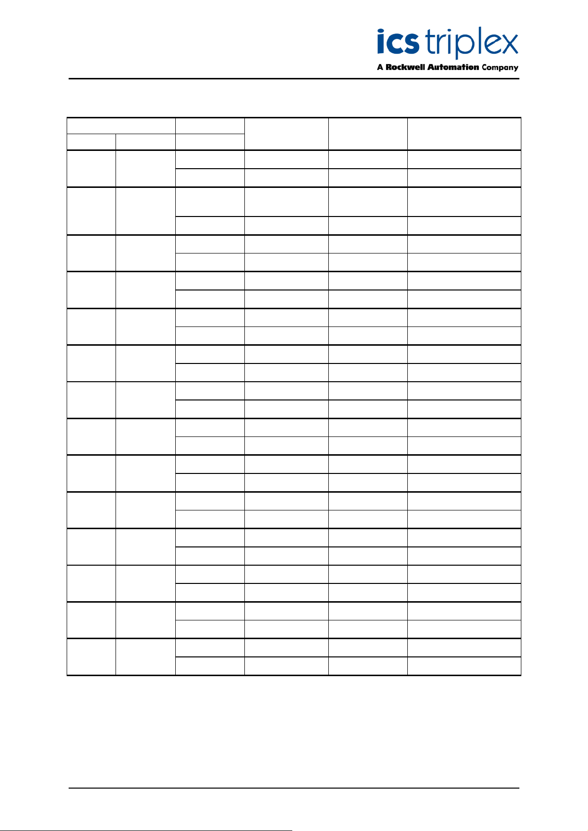
Issue Record
I
Number Date Revised by Technical Check Authorised by Modification
TM
Power Supply System T82xx
ssue
8 Sep 05 J W Clark Format
9 Mar 06 Pete Stock
Removed hidden
characters
Issue 9 Mar 06 PD-T82xx 2
Page 3

Trusted
TM
Power Supply System T82xx
This page is intentionally blank
Issue 9 Mar 06 PD-T82xx 3
Page 4

Trusted
TM
Power Supply System T82xx
Table of Contents
1. Description...................................................................................................................................7
1.1. Power Supply Chassis .................................................................................................................7
1.2. Power Supply Modules ................................................................................................................8
1.3. Input Power Regulation................................................................................................................9
1.4. Front Panel Indicators................................................................................................................11
1.4.1. Input Power Voltage Indicator....................................................................................................11
1.4.2. Output Power Display ................................................................................................................11
1.4.3. Output Power Indicator ..............................................................................................................11
2. Installation..................................................................................................................................12
2.1. Chassis Mounting ......................................................................................................................12
2.2. Backplane Versions and Module Keying ...................................................................................13
2.2.1. Input Power Terminals: TB1, TB2 (#8 screw terminals) ............................................................13
2.2.2. Output Power Terminals: TB3, TB4 (#6 screw terminals) .........................................................13
2.2.3. Status Connectors: J14, J15......................................................................................................14
2.2.4. Monitor Connector: J13..............................................................................................................14
3. Configuration..............................................................................................................................15
3.1. Current Sharing..........................................................................................................................15
3.2. REGENT Power Supply Load Units...........................................................................................15
3.3. Regent I/O Triplicated Power Distribution..................................................................................15
4. Maintenance ..............................................................................................................................16
5. Specifications.............................................................................................................................17
Figures
Figure 1 Power Supply Assembly.............................................................................................................7
Figure 2 Block Diagram of a dual ac I/O Power Supply Module...............................................................9
Figure 3 Block Diagram of a dual dc I/O Power Supply Module...............................................................9
Figure 4 Power Supply Chassis Front View............................................................................................12
Figure 5 Power Supply Chassis Rear View ............................................................................................12
Tabl es
Table 1 Chassis Types .............................................................................................................................7
Table 2 Module Types ..............................................................................................................................8
Table 3 Input Power Terminals...............................................................................................................13
Table 4 Output Power Terminals ............................................................................................................13
Table 5 Status Connectors .....................................................................................................................14
Issue 9 Mar 06 PD-T82xx 4
Page 5

Trusted
TM
Power Supply System T82xx
Notice
The content of this document is confidential to ICS Triplex Technology Ltd. companies and their
partners. It may not be given away, lent, resold, hired out or made available to a third party for any
urpose without the written consent of ICS Triplex Technology Ltd.
p
This document contains proprietary information that is protected by copyright. All rights are reserved.
Microsoft, Windows, Windows 95, Windows NT, Windows 2000, and Windows XP are registered
trademarks of Microsoft Corporation.
The information contained in this document is subject to change without notice. The reader should, in
all cases, consult ICS Triplex Technology Ltd. to determine whether any such changes have been
made. From time to time, amendments to this document will be made as necessary and will be
distributed by ICS Triplex Technology Ltd.
Information in this documentation set may be subject to change without notice and does not represent
a commitment on the part of ICS Triplex Technology Ltd.
The contents of this document, which may also include the loan of software tools, are subject to the
confidentiality and other clause(s) within the Integrator Agreement and Software License Agreement.
No part of this documentation may be reproduced or transmitted in any form or by any means,
electronic or mechanical, including photocopying and recording, for any purpose, without the express
written permission of ICS Triplex Technology Ltd.
Disclaimer
The illustrations, figures, charts, and layout examples in this manual are intended solely to illustrate the
text of this manual.
The user of, and those responsible for applying this equipment, must satisfy themselves as to the
acceptability of each application and use of this equipment.
This document is based on information available at the time of its publication. While efforts have been
made to be accurate, the information contained herein does not purport to cover all details or variations
in hardware or software, nor to provide for every possible contingency in connection with installation,
operation, or maintenance. Features may be described herein which are present in all hardware or
software systems. ICS Triplex Technology Ltd. assumes no obligation of notice to holders of this
document with respect to changes subsequently made.
ICS Triplex Technology Ltd. makes no representation or warranty, expressed, implied, or statutory with
respect to, and assumes no responsibility for the accuracy, completeness, sufficiency, or usefulness of
the information contained herein. No warranties of merchantability or fitness for purpose shall apply.
Issue 9 Mar 06 PD-T82xx 5
Page 6

Trusted
TM
Power Supply System T82xx
Revision and Updating Policy
All new and revised information pertinent to this document shall be issued by ICS Triplex Technology
Ltd. and shall be incorporated into this document in accordance with the enclosed instructions. The
change is to be recorded on the Amendment Record of this document.
Precautionary Information
WARNING
Warning notices call attention to the use of materials, processes, methods, procedures or limits which
must be followed precisely to avoid personal injury or death.
CAUTION
Caution notices call attention to methods and procedures which must be followed to avoid damage to
the equipment.
Notes:
Notes highlight procedures and contain information to assist the user in the understanding of the
information contained in this document
Warning
RADIO FREQUENCY INTERFERENCE
Most electronic equipment is influenced by Radio Frequency Interference (RFI). Caution should be
exercised with regard to the use of portable communications equipment around such equipment.
Signs should be posted in the vicinity of the equipment cautioning against the use of portable
communications equipment.
MAINTENANCE
Maintenance must be performed only by qualified personnel, otherwise personal injury or death, or
damage to the system may be caused.
Caution
HANDLING
Under no circumstances should the module housing be removed.
Associated Documents
Product Descriptions (PD) provide product specific information.
The Safety Manual contains the recommended safety requirements for the safety system design.
The PD8082B – Toolset Suite provides specific guidance on system configuration and application
generation.
The Operator and Maintenance Manual contains general guidelines on maintenance and diagnostic
procedures.
For technical support email: support@icstriplex.com
Issue 9 Mar 06 PD-T82xx 6
Page 7

Trusted
TM
Power Supply System T82xx
1. Description
The power supply assembly consists of a power supply chassis containing up to six power supply
modules. The chassis may be configured to distribute power in various combinations. For example, a
chassis containing six power supply modules may be set up with three modules providing triplicated
power for Regent+Plus I/O assemblies and three modules providing field power in a N+1 configuration.
Alternatively, the chassis may be set up to provide separate dual 24V dc supplies for both a Trusted
system and associated field devices.
TM
Figure 1 Power Supply Assembly
1.1. Power Supply Chassis
The power supply chassis houses a maximum of six power supply modules. It may be mounted in a
19-inch rack or flush mounted on a panel. Table 1 identifies the available types of chassis.
Catalogue
No.
T8200 I/O Power Supply Chassis 110-240V ac, 50/60 Hz Straight
T8201 I/O Power Supply Chassis 110-240V ac, 50/60 Hz Cross
T8202 I/O Power Supply Chassis 24V dc
Chassis Unit Input Power Voltage Configuratio
n
Bussed
Bussed
Table 1 Chassis Types
Issue 9 Mar 06 PD-T82xx 7
Page 8

Trusted
TM
Power Supply System T82xx
1.2. Power Supply Modules
The power supply assembly modules are single (if redundant inputs are not required) and dual input,
hot swap, user-replaceable ac and dc units. Table 2 identifies the available types of modules.
Catalogue
No.
T8220 Dual 110-240V ac 15V dc
T8222 Dual 24V dc 15V dc
T8223 Single 110-240V ac 24V dc
T8224 Single 110-240V ac 15 V dc
T8225 Dual 110-240V ac 24V dc
T8226 Dual 24V dc 24V dc
The dual inputs on the ac modules are galvanically isolated from each other. The inputs on the dc
modules are diode isolated and share a common return.
Input
Type
Input Power
Voltage
Table 2 Module Types
Output Power
Voltage
Issue 9 Mar 06 PD-T82xx 8
Page 9

Trusted
TM
Power Supply System T82xx
1.3. Input Power Regulation
A block diagram of a typical dual ac input I/O power supply module is shown in Figure 2. A block
diagram of a typical dual dc input I/O power supply module is shown in Figure 3.
H
igh Temp terature
I
Source
A
Source
B
I/P Filter & Protection
I/P Filter & Protection
Rectifier
Rectifier
PFC
PFC
Power Supply Module
/P A Fail
P
FC A Fai l
PFC A Of f
Status & Control
T1:b
T
1:c
Switching Regulator
P
FC B Off
P
FC B Fai l
I
/P B Fail
Status & Control
O
/P Current
R
emote Of f
F
ail
R
eset
PWM
T
1:a
DC
Output
Source
Source
Figure 2 Block Diagram of a dual ac I/O Power Supply Module
High Tempterature
I/P A Fail
Reset
Fail
Status & Control
DC
A
I/P Filter & Protection
T1:b
PWM
T1:a
Output
Switching Regulator
B
I/P Filter & Protection
O/P Current
Remote OffI/P B Fail
Status & Control
Power Supply Module
Figure 3 Block Diagram of a dual dc I/O Power Supply Module
Each primary power input is individually fused and filtered with both standard line filters and metal
oxide varistors (MOVs). The filters attenuate any high-frequency common mode and normal mode
noise present in the power distribution system. The MOVs clamp high-voltage transients.
Filter, rectifier, and power factor correction circuits convert primary ac input power to bulk dc voltage.
The switching regulator converts bulk dc power to regulated dc output voltage. Sensing, status, control
and timing circuits provide for the following:
Issue 9 Mar 06 PD-T82xx 9
Page 10

Trusted
TM
Power Supply System T82xx
•
Input power failure - Active low status output. Indicates when the input voltage is below
•
5
8
• Bulk power failure - Active high status output on ac input modules only. Indicates the dc bulk
voltage (PFC output) is outside the specified range. There is a separate signal for each input.
• High-temperature warning alarm - Both an active high and active low status output are
provided. Indicates the module temperature exceeds 75
the air inlet (bottom) of the module.
• High-temperature shutdown - Internal signal that will shut down the switching regulator if
module temperature is above 85
the module.
• Output over-voltage - Internal signal that will shut down the switching regulator if the output
voltage exceeds +18
voltage protection circuitry activation is a permanent error condition, requiring manual
intervention to return module to normal operation.
• dc output fail - Active high status output indicates the dc output voltage has gone out of
regulation. The dc output fail threshold is 13.75
21.75V dc (±0.25V dc) for the 24 volt module.
V ac
or 18
There is a separate signal for each input.
V dc.
°C. The temperature is sensed near the air inlet (bottom) of
V dc for the 15 volt module and +28V dc for the 24 volt module. Over-
°C. The temperature is sensed near
V dc (±0.25V dc) for the 15 volt module, and
• Output current limiting - Internal signal limits output current in excessive current demand
situations.
• POWER FAIL - Active high status signal that indicates impending loss of output power due to
one of the following:
• - Both inputs have indicated power failure
• - Remote off control signal activated
• - Thermal shutdown
• - Output-over voltage
• RESET - Active high status signal that is generated a minimum of 10 ms (ac input module) or
0.5ms (dc input module) after a POWER FAIL signal. RESET remains asserted for 200ms
(minimum) after module power-up.
• PFC off - Active low input that turns off the power factor correction of an individual input. This
signal provides the capability to test the input circuitry of a module by turning off each input
independently while monitoring the module fail signal
• Remote off - Active low input that turns off the output power of a module.
Note: Bulk Power Fail, PFC Off and Remote Off are accessed through the monitor module connector
on the chassis backplane. The monitor module connector allows for a future development of a
monitor card that would provide remote control and enhanced monitoring of the power supply
chassis.
Active low signals are not maintained while RESET is active. All status signals are open collector and
require external pull-up resistors.
RESET is used in the Regent I/O transceivers for power system interlocking within the I/O system. A
power failure (either input power or module fault) activates RESET and turns off the dc output front
panel indicator.
The POWER FAIL and RESET signals are required for proper operation of Regent I/O transceivers
and I/O modules during power up, power down, and loss of power. Refer to Assembly Installation in
the associated Regent Product Description for details of connecting these signals to a Regent I/O
chassis.
Issue 9 Mar 06 PD-T82xx 10
Page 11

Trusted
TM
Power Supply System T82xx
1.4. Front Panel Indicators
he front panel of each I/O power supply module supports three LED indicators detailed in the
T
following sub-paragraphs
1.4.1. Input Power Voltage Indicator
Each green INPUT POWER indicator is lit when the associated input (Input A, Input B) is above the
lower input voltage threshold.
1.4.2. Output Power Display
The 10-segment LED indicator bar displays the approximate output current level percentage (0% 100%)
1.4.3. Output Power Indicator
The DC Output indicator is lit when the I/O power supply module's dc output is within tolerance. Out-oftolerance conditions, loss of input power or brown-out, and module failures turn off this indicator.
Issue 9 Mar 06 PD-T82xx 11
Page 12

Trusted
TM
Power Supply System T82xx
2. Installation
2.1. Chassis Mounting
Figure 4 and Figure 5 show the front and rear views of the power supply chassis.
9"
1
TB3
J1 J2 J3 J4 J6J5
J15
TB1
Input
Crossover
J14
J13
J7 J8 J12J11J9J10
Patch
10.5"
Figure 4 Power Supply Chassis Front View
TB4
TB2
Figure 5 Power Supply Chassis Rear View
Issue 9 Mar 06 PD-T82xx 12
Page 13

Trusted
6E
6E
6E
6E
6E
Mounting flanges can be attached to either the rear or the front of the chassis. This allows flush
mounting the chassis to a panel or mounting in a 19-inch rack.
The input crossover patch is on the T8200 chassis only.
TM
Power Supply System T82xx
Input Crossover Patch configured for no crossover,
source 1 and source 2 are connected to input A and
input B respectively for all modules slots.
Input Crossover Patch configured to swap source 1 and
source 2 for modules slots 4 through 6.
Source 1 and source 2 are connected to input A and
input B respectively for slots 1-3.
Source 1 and source 2 are connected to input B and
input A respectively for slots 4-6.
6E5 6E6
6E7 6E8
6E3 6E4
6E1 6E2
6E5
6E1
2.2. Backplane Versions and Module Keying
Connector placement on ac input modules and backplanes differ from dc modules and backplanes.
This prohibits insertion of the wrong input module type into a backplane.
Module slots in a chassis can be individually keyed to only accept a module of an particular output
voltage.
2.2.1. Input Power Terminals: TB1, TB2 (#8 screw terminals)
Terminal No. T8200 T8202 Source
1 N DC- B
2 L DC+
3 N DC- A
4 L DC+
Table 3 Input Power Terminals
2.2.2. Output Power Terminals: TB3, TB4 (#6 screw terminals)
Terminal No. Module Slot T8200, T8202
12 6
11 5
10 4 + DC Output
9 3
8 2
7 1
6
5
4 1-6 DC Return
3 (terminals 1-6 are
2 Connected together on
1 Backplane)
Table 4 Output Power Terminals
Issue 9 Mar 06 PD-T82xx 13
Page 14

Trusted
TM
Power Supply System T82xx
2.2.3. Status Connectors: J14, J15
ype: 10 pin shrouded header, double row, 0.100 x 0.100 Centres
T
Manufacturer: AMP
Manufacturer Part No: 102618-3
Mating Connector: AMP 87631-5
Pin Out:
Pin J14 J15
Slot Signal Slot Signal
1
2 All Input ‘A’ Fail
3 All Input ‘B’ Fail
4 All Hi Temperature
5 1 Reset 4 Reset
6 1 Power Fail 6 Reset
7 2 Reset 4 Power Fail
8 3 Power Fail 6 Power Fail
9 2 Power Fail 5 Power Fail
10 3 Reset 5 Reset
Table 5 Status Connectors
2.2.4. Monitor Connector: J13
Type: 72 pin Edge Connector, 0.125” centreline
Manufacturer.: AMP
Manufacturer Part No: 1-530844-9
Pin Out: Not Configured
Issue 9 Mar 06 PD-T82xx 14
Page 15

Trusted
TM
Power Supply System T82xx
3. Configuration
3.1. Current Sharing
The modules are capable of current sharing by connecting their outputs together in parallel. This can
be done external to the chassis or by using a shorting bar that mounts directly to the output terminals
on the chassis backplane. This allows separate groups of modules from within a single chassis to have
their outputs configured as Single, Dual or N+1. The module uses a passive ‘droop’ method of current
sharing and will share to within 25% of the rated load.
3.2. REGENT Power Supply Load Units
When using the power supply system with Regent and Regent+Plus , power supply loading is based
on the number of I/O modules in the I/O chassis and the load imposed by each I/O module. Load units
for each I/O module are shown in that module’s product description and specification sheet under the
Safetybus Power heading. A set of three power supply modules will provide the following load units:
Available Load Units (for a set of three power supplies)
Number of I/O Units
(Chassis):
Load Unit Capacity:
Calculating the number of load units in the system helps determine the number of I/O power supplies
required by the system. For economic power distribution, and to avoid overloading individual power
supply units, calculate power supply loading when configuring systems.
1
82
2
78
3
74
4
70
3.3. Regent I/O Triplicated Power Distribution
A chassis can contain two sets of triple-redundant power supplies for Regent I/O. Each of the tripleredundant I/O power supply modules within the I/O power supply chassis provides power for one leg of
the three redundant legs of the I/O Safetybus transceivers, and provides power to all the I/O modules
within its associated I/O chassis. Each I/O module contains a diode OR power-sharing circuit that
receives power from all three I/O power supply modules.
Should any I/O power supply module fail, only one leg of the transceiver modules loses power: the two
remaining legs maintain proper Regent operation. In addition, all the I/O modules continue to operate
properly by drawing their current from the two remaining power supplies within the I/O power supply
assembly.
I/O transceivers and I/O modules require power fail and reset status signals for proper operation.
Issue 9 Mar 06 PD-T82xx 15
Page 16

Trusted
TM
Power Supply System T82xx
4. Maintenance
No periodic maintenance or calibration is required for I/O power supply modules. There are no userreplaceable parts.
A failed I/O power supply module can be hot-replaced without disrupting system operations. Main
power wiring and I/O power cables (connected to the chassis) are not disturbed during module
replacement.
Issue 9 Mar 06 PD-T82xx 16
Page 17

Trusted
TM
Power Supply System T82xx
5. Specifications
Voltage Range
T8220, T8223, T8224, T8225
T8222, T8226
Frequency Range
T8220, T8223, T8224, T8225
Inrush Current (120/260V ac)
T8220, T8223, T8224, T8225
85V ac to 264V ac
20V dc to 32V dc
47Hz to 63Hz
20/40A (peak) Cold, 35/65A
(peak) Hot
Power Factor 0.95 min.
Efficiency 70%
Use with Chassis:
T8220, T8223, T8224, T8225
T8222, T8226
Fusing (Internal to module)
T8220, T8223, T8224, T8225
T8222, T8226
Output Voltage
T8220, T8222, T8224,
T8223, T8225, T8226
T8200
T8202
6A, 250V, 3AG Slow Blow
20 A, 250V, 3AB Slow Blow
+15V dc
+24V dc
Output Power 250W, per module
Power Hold-up Time
T8220, T8223, T8224, T8225
T8222, T8226
Operating Temperature –5
Non-operating Temperature -25
Operating Humidity
Environmental Specifications Refer to Document 552517
Module Dimensions
Height:
Width:
Depth:
Chassis Dimensions
Height:
Width:
Depth:
20ms, minimum
1ms, minimum
0
C to 600C (230to 1400F)
0
to 700C (-250to 1580F)
5 to 95% RH
266mm (10.47in)
61mm (2.38in)
318mm (2.5in)
266mm (10.47in)
483mm (19in)
343mm (13.5in)
Module Weight 3.25kg (7.2lbs)
Chassis Weight 7kg (15.4lbs)
Issue 9 Mar 06 PD-T82xx 17
Page 18

 Loading...