

Page 1
SDS-8293
TM
Trusted
Industrial Control System
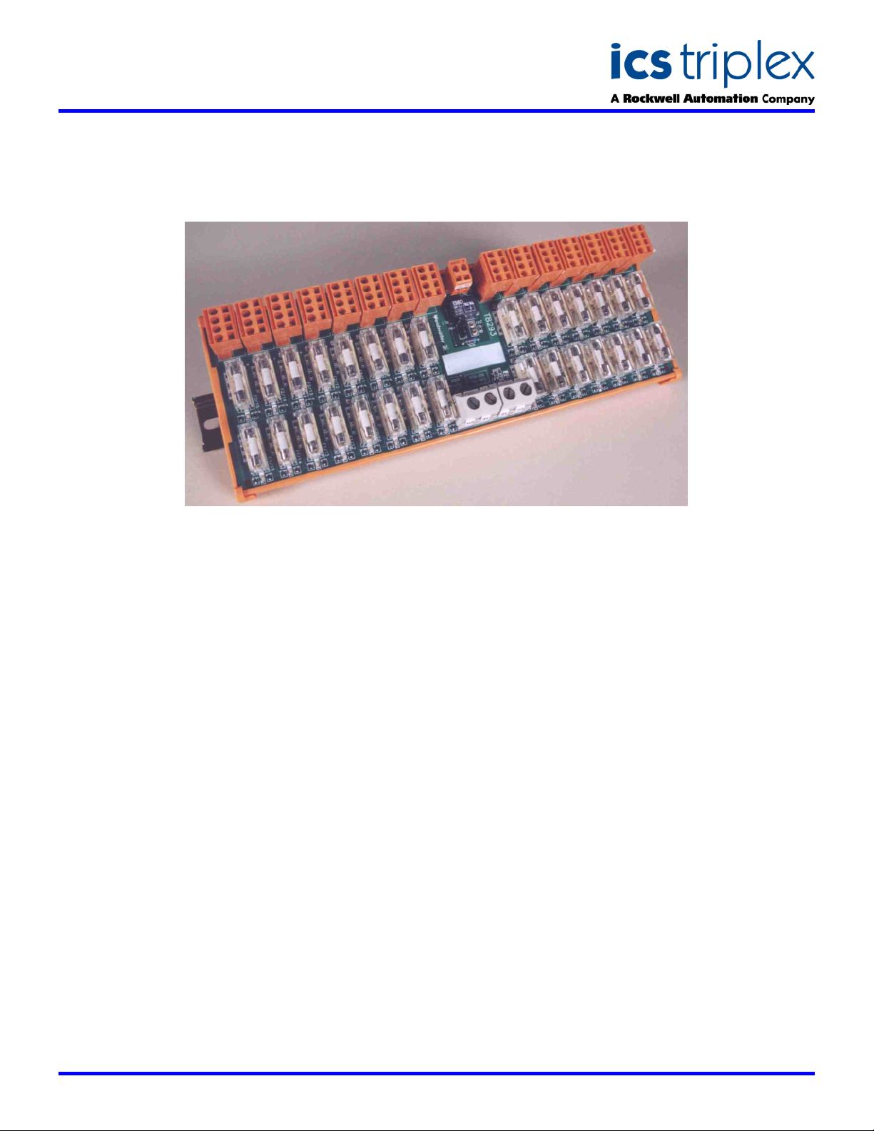
TrustedTM Power Distribution Unit 15-Way Fused-T8293
GENERAL ASSEMBLY
DESCRIPTION
The Trusted
Unit 15-way Fused provides 15
dual redundant fused power
outputs from dual redundant 24V
dc or 48V dc incoming power
feeders. The Unit is designed to
be mounted on a DIN rail.
On-board monitoring circuits
provide local LED indication of
individual fuse failure (red LED).
A common fuse failure alarm
signal is provided by the Unit via
a volt-free relay contact output.
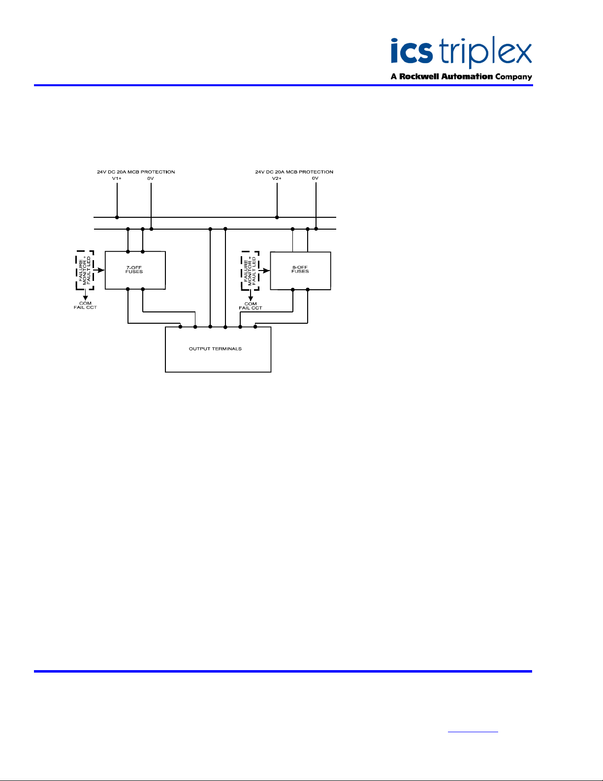
Two 24V dc or 48V dc (link
selectable) supplies, are
distributed through 30 fuses,
arranged in two banks of 15
fuses. The outputs are fed via 15
terminal blocks labelled T1 to T7,
and T11 to T18.
TM
Power Distribution
Each supply shares a common
0V reference.
A volt-free relay contact provides
the fuse failure common alarm
signal (contact open for fuse
failure) for connection to external
alarm monitoring circuits.
FEATURES
Fifteen ‘dual’ 24V dc or 48V
dc, 3A fuse protected
outputs – suitable for direct
connection to Trusted
Field Termination
Assemblies (FTAs), or other
equipment
TM
Visual indications of input
power supply status
Visual indication of
individual fuse status
Common alarm of fuse
status via volt-free contact
Link-selectable supply
voltage options
Issue 5 Jan 2006
Page 2
SDS-8293
Trusted
TM
Industrial Control System
TrustedTM Power Distribution Unit 15-Way Fused-T8293
BLOCK DIAGRAM
ELECTRICAL SPECIFICATION
Voltage Range
Supply Current
Supply Connection
Supply Conductor Clamping
Range - solid
stranded
AWG Conductors
Input Power Supply Indication
Output Indication
Fused Outputs
Fuse Type
Leakage Current (failed fuse)
Output Connector
Output Conductor Clamping
Range
Common Alarm Output
Maximum Switching Voltage
Minimum Load
22-30V dc or 43-60V dc (link selectable)
23A maximum
LU10.16 screw clamp terminal
0.5 to 16mm
0.5 to 10mm
2
2
No. 22…8
2-off green LEDs
30-off red LEDs indicating individual
failed fuses
30 arranged in two banks of 15
3A 5x20mm cartridge
0.6mA @ 30V dc or 1.2mA @ 60V dc
maximum
BLZ 2-part terminal
0.5 to 2.5mm
2
AWG Conductors 28...14
Volt-free contact – powered, closed in
healthy state
60V dc or 125V ac @ 0.5A
5V @ 1mA
MECHANICAL
SPECIFICATION
Dimensions (HxWxD):
79mm x 285mm x 109mm
(3.1ins x 11.2ins x 4.3ins)
Weight:
576g
(1.3lbs)
ENVIRONMENTAL
Operating Temperature:
-5°C to 60°C
(23°F to 140°F)
Operating Humidity:
5 to 95%, non-condensing
Vibration:
10 to 57Hz ±0.075mm
57 to 150Hz 1.0g
Shock:
15g, ½ sine wave, 11ms
EMI (IEC 801):
ESD
Air discharge to 15kV
Contact discharge to 8kV
Radiated Fields
10V/m, 27MHz to
500MHz
Transients and Bursts
2kV, 2.5kHz for
t=60 seconds
ICS Triplex
Technical data sheets are intended for
information and guidance. The Company
has a policy of continual product
development and improvement.
Specifications are subject to change
without notice. For latest information, visit
our Websi te:- www.icstri plex.com
 Loading...