

Page 1
SDS-8292
TM
Trusted
Industrial Control System
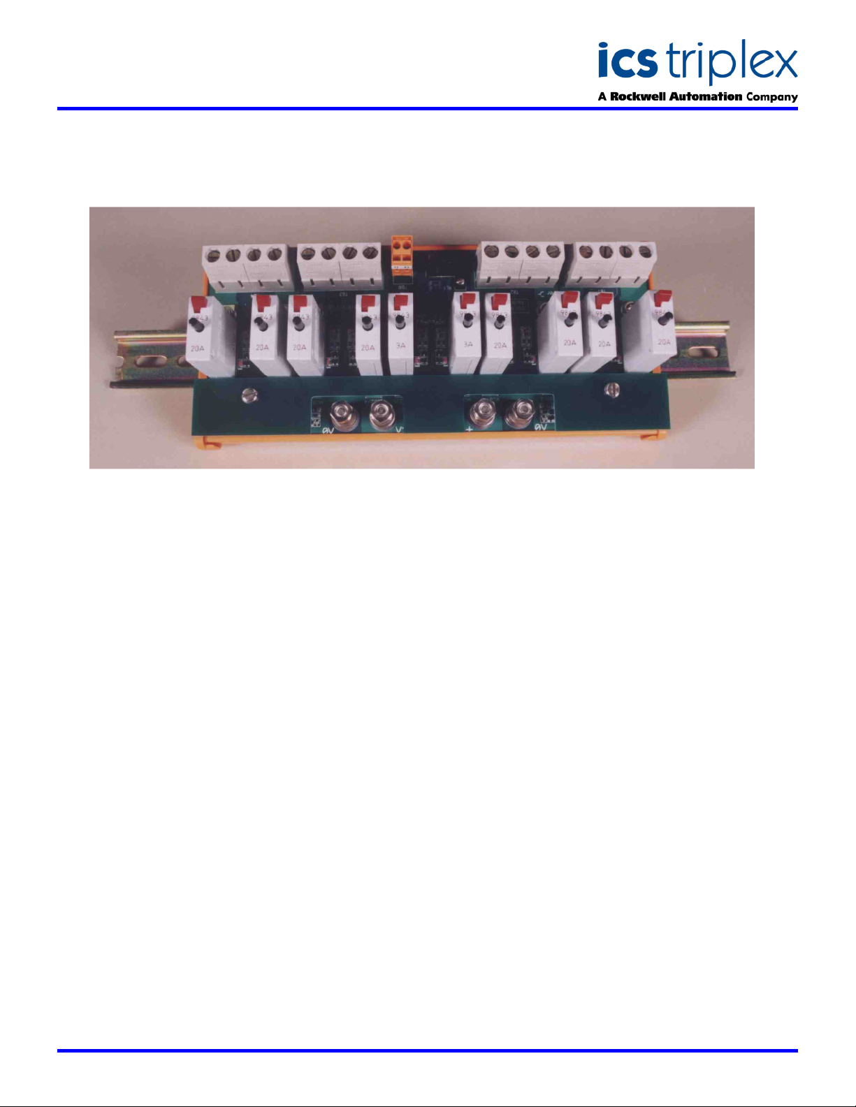
TrustedTM Power Distribution Unit MCB 24V-T8292
GENERAL ASSEMBLY
DESCRIPTION
The dual 5-channel Trusted
MCB 24V is designed for N+1 or 100% redundant 24V
dc power distribution applications. The unit is designed
to be mounted on a standard DIN rail. Monitoring
circuits provide local LED indication of individual MCB
‘trip’ status and a relay contact provides a common
alarm signal output.
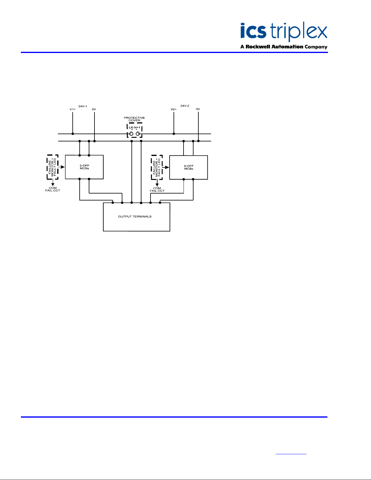
Power fed to the Trusted
MCB 24V is sub-distributed via the dual MCBs either
as an N+1 or 100% redundant configuration, via the
fitting (for N+1) or removal of the board mounted link,
LK-N+1.
The standard factory-fitted configuration is N+1.
Each MCB is monitored for open circuit condition and
provides a local on-board LED indication of individual
‘trip’ status (red LED displayed for tripped).
A volt-free relay contact provides the common alarm
output signal (contact open for tripped) for connection
to external alarm monitoring circuits.
TM
Power Distribution Unit
TM
Power Distribution Unit
FEATURES
Four ‘dual’ 24V dc 20A MCB protected outputs
– suitable for direct connection to a Trusted
Controller/Expander Chassis or upstream
protection for the Trusted 15-way Fused
Distribution Unit T8293
TM
One ‘dual’ 24V dc 3A MCB protected output –
suitable for direct connection to Trusted Fan
Trays or other low power devices
Visual indication of MCB status
Common alarm output of MCB status via a volt-
free contact
Option link for N+1 or 100% redundant
distribution
Issue 5 Jan 2006
Page 2
SDS-8292
Trusted
TM
Industrial Control System
TrustedTM Power Distribution Unit MCB 24V-T8292
BLOCK DIAGRAM
ELECTRICAL SPECIFICATION
Voltage Range
Supply Current
Input Supply Indication
MCB Operation Indication
MCB Outputs
Leakage Current (open MCB)
Common Alarm Output
Maximum Switching Voltage
Maximum Switching Current
Minimum Load
22-28V dc
60A maximum
2-off green LEDs – one per feeder
10-off red LEDs – one per MCB
8-off 24V dc @ 20A
2-off 24V dc @ 3A
0.6mA @ 28V dc maximum
1-off N/O contact
60V dc or 125V ac
0.5A
5V dc @ 1mA
MECHANICAL
SPECIFICATION
Dimensions (HxWxD):
108mm x 240mm x 109mm
(4.2ins x 9.4ins x 4.3ins)
Weight:
823g
(1.8lbs)
ENVIRONMENTAL
Operating Temperature:
Forced Cooled
-5°C to 60°C
(23°F to 140°F)
Operating Humidity:
5 to 95%, non-condensing
Vibration:
10 to 57Hz ±0.075mm
57 to 500Hz 1.0g
Shock:
15g, ½ sine wave, 11ms
EMI (IEC 801):
ESD
Air discharge to 15kV
Contact discharge to 8kV
Radiated Fields
10V/m, 27MHz to
500MHz
Transients and Bursts
2kV, 2.5kHz for
t=60 seconds
ICS Triplex
Technical data sheets are intended for
information and guidance. The Company
has a policy of continual product
development and improvement.
Specifications are subject to change
without notice. For latest information, visit
our Websi te:- www.icstr iple x.com
 Loading...