

Page 1
TrustedTM
PD-T8173
Introduction
Trusted
TM
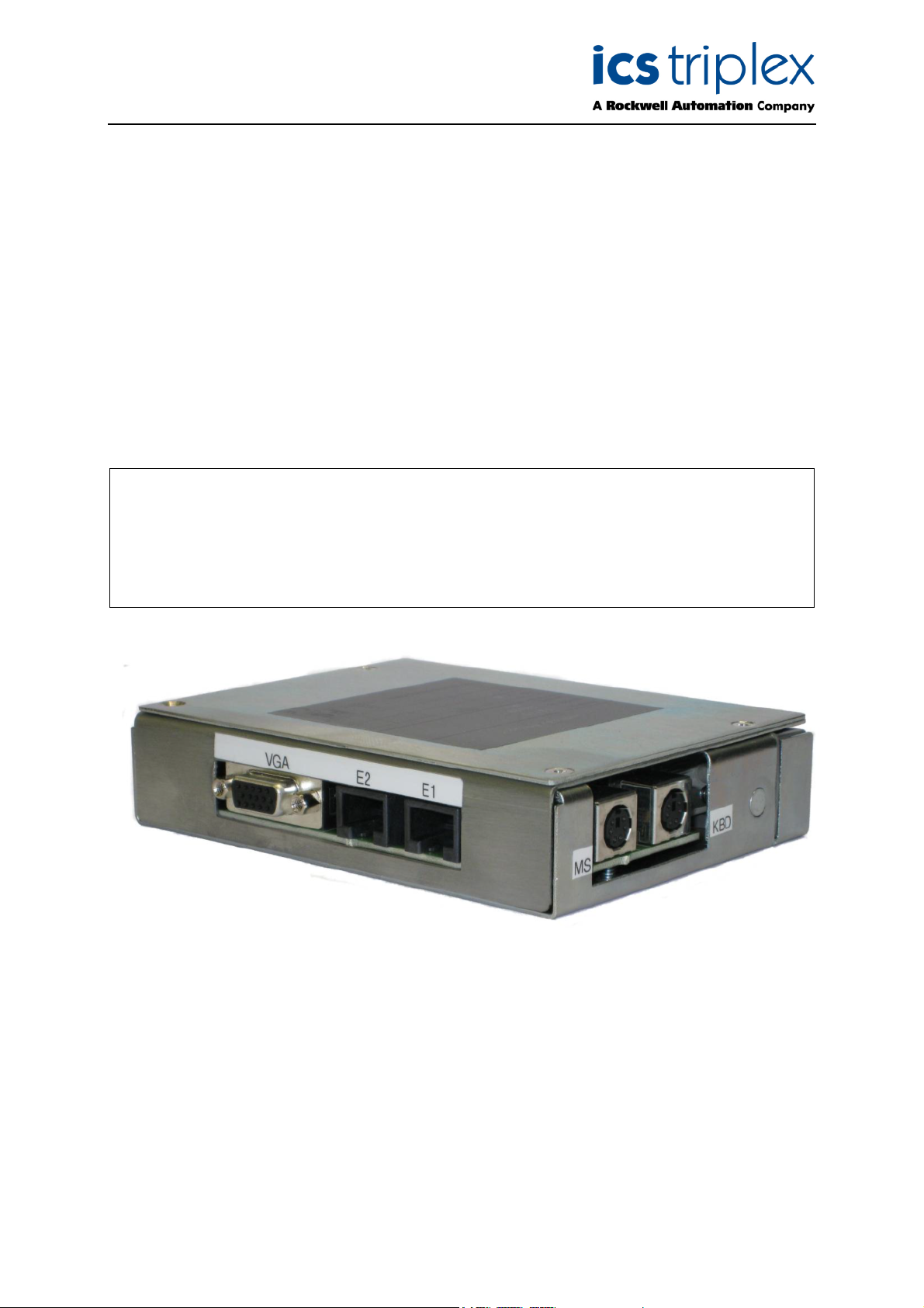
Gateway Adaptor
This document contains general information about the TrustedTM Gateway Adaptor T8173. The
adaptor provides direct access to the Ethernet, video, mouse and keyboard ports of the Trusted
Gateway Module T8170 and interfaces them to external connections. This access can be used for
local maintenance and for external communication.
The adaptor will also work with the T8151B communications interface, connecting its Ethernet ports to
external connections. Note, it does not connect serial ports.
Features
TM
• Provides easy access for external systems to communicate with a Trusted
TM
• Simple installation; connects directly to the rear of the Trusted
• Provides connections for PS/2 Keyboard, PS/2 Mouse and VGA monitor.
Gateway Module.
System.
TM
Figure 1 T8173 Gateway Adaptor
Page 2
Trusted
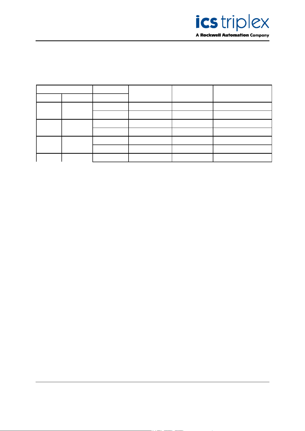
Issue Record
Issue
Number Date Revised by Technical CheckAuthorised by Modification
01 Feb 10 N Owens A Holgate P Stock Initial Issue
TM
Gateway Adaptor T8173
Issue 01 Feb 10 PD-T8173 2
Page 3

Trusted
TM
Gateway Adaptor T8173
Table of Contents
1.1. Associated Equipment....................................................................................................................6
2. Description...........................................................................................................................................6
2.1. Ethernet Ports Connections ...........................................................................................................7
2.2. Keyboard and Mouse Port Connections.........................................................................................7
2.3. Monitor VGA port............................................................................................................................7
3. Installation............................................................................................................................................7
3.1. Gateway Module Connections........................................................................................................8
3.1.1. Connector (SK1)........................................................................................................................8
3.1.2. RJ45 Ethernet Connectors for 10/100BaseT Networks ............................................................9
3.1.3. Connectors for Keyboard and Mouse........................................................................................9
3.1.4. Monitor Connector.....................................................................................................................9
4. Specifications ....................................................................................................................................10
Figures
Figure 1 T8173 Gateway Adaptor.............................................................................................................1
Figure 2 T8173 Internal Layout................................................................................................................6
Tables
Table 1 Associated Equipment ...............................................................................................................6
Table 2 SK1 Connector pin-out ................................................................................................................8
Table 3 Ethernet RJ45 Connectors Pin-out ..............................................................................................9
Table 4 PS/2 Connectors Pin-out .............................................................................................................9
Table 5 VGA Connector Pin-out ...............................................................................................................9
Issue 01 Feb 10 PD-T8173 3
Page 4

Trusted
TM
Gateway Adaptor T8173
Notice
The content of this document is confidential to ICS Triplex Technology Ltd. companies and their
partners. It may not be given away, lent, resold, hired out or made available to a third party for any
purpose without the written consent of ICS Triplex Technology Ltd.
This document contains proprietary information that is protected by copyright. All rights are reserved.
Microsoft, Windows, Windows 95, Windows NT, Windows 2000, and Windows XP are registered
trademarks of Microsoft Corporation.
The information contained in this document is subject to change without notice. The reader should, in
all cases, consult ICS Triplex Technology Ltd. to determine whether any such changes have been
made. From time to time, amendments to this document will be made as necessary and will be
distributed by ICS Triplex Technology Ltd.
Information in this documentation set may be subject to change without notice and does not represent
a commitment on the part of ICS Triplex Technology Ltd..
The contents of this document, which may also include the loan of software tools, are subject to the
confidentiality and other clause(s) within the Integrator Agreement and Software License Agreement.
No part of this documentation may be reproduced or transmitted in any form or by any means,
electronic or mechanical, including photocopying and recording, for any purpose, without the express
written permission of ICS Triplex Technology Ltd.
Disclaimer
The illustrations, figures, charts, and layout examples in this manual are intended solely to illustrate the
text of this manual.
The user of, and those responsible for applying this equipment, must satisfy themselves as to the
acceptability of each application and use of this equipment.
This document is based on information available at the time of its publication. While efforts have been
made to be accurate, the information contained herein does not purport to cover all details or variations
in hardware or software, nor to provide for every possible contingency in connection with installation,
operation, or maintenance. Features may be described herein which are present in all hardware or
software systems. ICS Triplex Technology Ltd. assumes no obligation of notice to holders of this
document with respect to changes subsequently made.
ICS Triplex Technology Ltd. makes no representation or warranty, expressed, implied, or statutory with
respect to, and assumes no responsibility for the accuracy, completeness, sufficiency, or usefulness of
the information contained herein. No warranties of merchantability or fitness for purpose shall apply.
Revision and Updating Policy
All new and revised information pertinent to this document shall be issued by ICS Triplex Technology
Ltd. and shall be incorporated into this document in accordance with the enclosed instructions. The
change is to be recorded on the Amendment Record of this document.
Issue 01 Feb 10 PD-T8173 4
Page 5

Trusted
TM
Gateway Adaptor T8173
Precautionary Information
WARNING
Warning notices call attention to the use of materials, processes, methods, procedures or limits which
must be followed precisely to avoid personal injury or death.
CAUTION
Caution notices call attention to methods and procedures which must be followed to avoid damage to
the equipment.
Notes:
Notes highlight procedures and contain information to assist the user in the understanding of the
information contained in this document
Warning
RADIO FREQUENCY INTERFERENCE
Most electronic equipment is influenced by Radio Frequency Interference (RFI). Caution should be
exercised with regard to the use of portable communications equipment around such equipment.
Signs should be posted in the vicinity of the equipment cautioning against the use of portable
communications equipment.
MAINTENANCE
Maintenance must be performed only by qualified personnel, otherwise personal injury or death, or
damage to the system may be caused.
Caution
HANDLING
Under no circumstances should the module housing be removed.
Associated Documents
Product Descriptions (PD) provide product specific information.
The Safety Manual contains the recommended safety requirements for the safety system design.
The PD8082B – Toolset Suite provides specific guidance on system configuration and application
generation.
The Operator and Maintenance Manual contains general guidelines on maintenance and diagnostic
procedures.
For technical support email: support@icstriplex.com
Issue 01 Feb 10 PD-T8173 5
Page 6

Trusted
TM
Gateway Adaptor T8173
1.1. Associated Equipment
Part Number Product Name Description
T8170 Gateway Module Single board module, primarily supporting OPC server
Communications
T8151B
Interface Multiple communications links to external systems
Table 1 Associated Equipment
2. Description
The TrustedTM Gateway Adaptor T8173 is designed to be connected directly to the rear of a Gateway
module in a Controller Chassis T8100. The adaptor provides two Ethernet communications
connections to remote systems and local connection (keyboard, video and mouse) for the Gateway
module maintenance. Connection between the adaptor and the Gateway module is by a 78 × 2-way
Inverse DIN41612 M-type connector (SK1). Figure 2 shows the physical layout of the adaptor with a
side plate removed.
Figure 2 T8173 Internal Layout
Issue 01 Feb 10 PD-T8173 6
Page 7

Trusted
The adaptor comprises a printed circuit board (PCB) on which the communications ports and socket
SK1 are mounted. The adaptor is contained within a metal enclosure and SK1 connects to a T8170
connector at the rear of the controller chassis. This connector is held in position by clips and a release
button is provided to enable the adaptor to be disconnected.
The communications ports available for external connectors on the adaptor are Ethernet (10BaseT and
100BaseT), P/S2 keyboard, P/S2 mouse and VGA video.
TM
Gateway Adaptor T8173
2.1. Ethernet Ports Connections
Ethernet ports 1 and 2 connect to 10/100BaseT networks by two RJ45 connectors.
2.2. Keyboard and Mouse Port Connections
CAUTION
These are P/S2 ports. Unlike USB keyboards and mice, the ports will only work if the device is plugged
into the port when starting the module. Plugging a keyboard or mouse into a running Gateway module
may damage the module’s port or the device.
To use the, monitor, keyboard and mouse ports, first remove the Gateway module, then install the
adaptor and attach the devices to the appropriate ports on the adaptor (including the monitor), and reinsert the Gateway module. The port marked KB nearest to the chassis is the keyboard port and the
port marked MS nearest to the Ethernet sockets is the mouse port (see Figure 1Error! Reference
source not found.).
2.3. Monitor VGA port
The VGA port is compatible with 15-pin three-row connectors found on monitors. The Gateway module
runs Windows XP and defaults to 1024x768, 32-bit colour graphics, which will be visible on all new and
nearly all old monitors. The VGA port should ideally be connected at the same time as the keyboard
and mouse are with the Gateway module disconnected, although this is not critical.
3. Installation
Remove communications interface or Gateway module and connect socket SK1 at the rear of the
chassis. Slide it up until it clicks into place.
Issue 01 Feb 10 PD-T8173 7
Page 8

Trusted
TM
Gateway Adaptor T8173
3.1. Gateway Module Connections
3.1.1. Connector (SK1)
SK1 is a 78 ×2-way DIN41612, Inverse M-type connector.
CONNECTOR SK1 PINOUT
Pin
29 LINK
28
27
26
25
24
23
22 Monitor R Monitor G Monitor B
21 Monitor VSync Monitor HSync Monitor VCC
20 Monitor Data Monitor Clock Monitor 0V
19
18 Keyboard Clock Keyboard Data
17 Mouse Clock Mouse Data 0V
16
15
14
13
12 Ethernet 1 TD+ Ethernet 1TD-
11 Ethernet 1RD+ Ethernet 1RD-
10 Ethernet 1 GND
9
8 Ethernet 2 TD+ Ethernet 2 TD-
7 Ethernet 2 RD+ Ethernet 2 RD-
6 Ethernet 2 GND
5
4 LINK
A B C
Table 2 SK1 Connector pin-out
Issue 01 Feb 10 PD-T8173 8
Page 9

Trusted
TM
Gateway Adaptor T8173
3.1.2. RJ45 Ethernet Connectors for 10/100BaseT Networks
Pin Service
1 TD+
2 TD-
3 RD+
4
5
6 RD-
Table 3 Ethernet RJ45 Connectors Pin-out
3.1.3. Connectors for Keyboard and Mouse
These are PS/2 connectors.
Pin Service
5 Clock
1 Data
4 VCC
3 0V
Table 4 PS/2 Connectors Pin-out
3.1.4. Monitor Connector
This is a 15-pin VGA connector.
Pin Service
1 Red Video
2 Green Video
3 Blue Video
15 Clock
12 Data
14 Vertical Synch
13 Horizontal Synch
9 VCC
5,6,7,8,10 0V
Female socket as
on motherboard
Male plug as on
keyboard/mouse
Table 5 VGA Connector Pin-out
Issue 01 Feb 10 PD-T8173 9
Page 10

Trusted
TM
Gateway Adaptor T8173
Notes: An earth point is provided on the PCB of the assembly so that the chassis earth of the
Trusted
TM
communications interface is connected to both the enclosure and module rack earth.
4. Specifications
Ports
PS/2
Video
Ethernet
Operating Temperature
Non-operating Temperature
Operating Humidity
Environmental Specifications
Dimensions
Height:
Width:
Depth: (including mounting rail)
Weight
Keyboard and Mouse
VGA
2 × (10BaseT or 100BaseT)
0
C to 600C (230F to 1400F)
–5
0
–25
C to 700C (–130F to 1580F)
5 to 95% RH
Refer to Document 552517
150mm (5.9in.)
28mm (1.1in.)
106mm (4.2in.)
418g (0.92lbs.)
Issue 01 Feb 10 PD-T8173 10
 Loading...