

Page 1

TrustedTM
PD-T8141
TM
Trusted
Demonstration Unit
Introduction
The TrustedTM Demonstration Unit T8141 provides a portable Simulation system utilising the TrustedTM
Chassis, TMR Processor and Modules available from the standard product range together with a
purpose built panel for the supply of field simulation input and output signals.
The unit offers the ability to run any Trusted
types configured for Companion slot. The unit is suitable for sales demonstrations, product
familiarisation for engineers, training courses and to simulate IEC1131 Trusted
including development of application programs.
For shipping worldwide to customer locations, the unit is fitted within a wheeled flight case allowing
easy transit and set up on arrival. It does not require assembly other than fitting the power lead and
TC-304-01 Comms link to a suitable PC installed with the Trusted
TM
software configuration and simulate a selection of I/O
TM
Toolset programs
TM
Toolset T8082B.
Once powered and connected to the PC either a demo program is loaded to utilise the field simulation
I/O or the unit can be used as a tool to run a “real” application.
Typical configuration for training and demonstration purposes is a TMR Processor, Communications
Interface Module, Digital Input and Output Modules, Analogue Input Modules, with at least two of a
similar type to demonstrate “Hot Swap” capability.
Companion slot hoods may be removed from the chassis to allow connection of any cable or Interface
Adaptor type and associated modules.
Features
TM
• Full Trusted
• 100-240Vac Input
• Portable wheeled flight case
• Simulation of 60 Field Signals
• Pre wired Dual Ethernet (point to point and hub)
• Serial Comms wired to terminals
• Configured for Companion Slot DI, AI and DO modules
• Fully Compliant with All Trusted
Controller Capability
TM
Software Packages
• Field Faults Simulated
Issue 1 Feb 06 PD-T8141 1
Page 2

Trusted
Issue Record
Issue
Number Date Revised by Technical CheckAuthorised by Modification
1 Feb 06 N Owens Initial Issue
TM
Demonstration Unit T8141
Issue 1 Feb 06 PD-T8141 2
Page 3
Trusted
TM
Demonstration Unit T8141
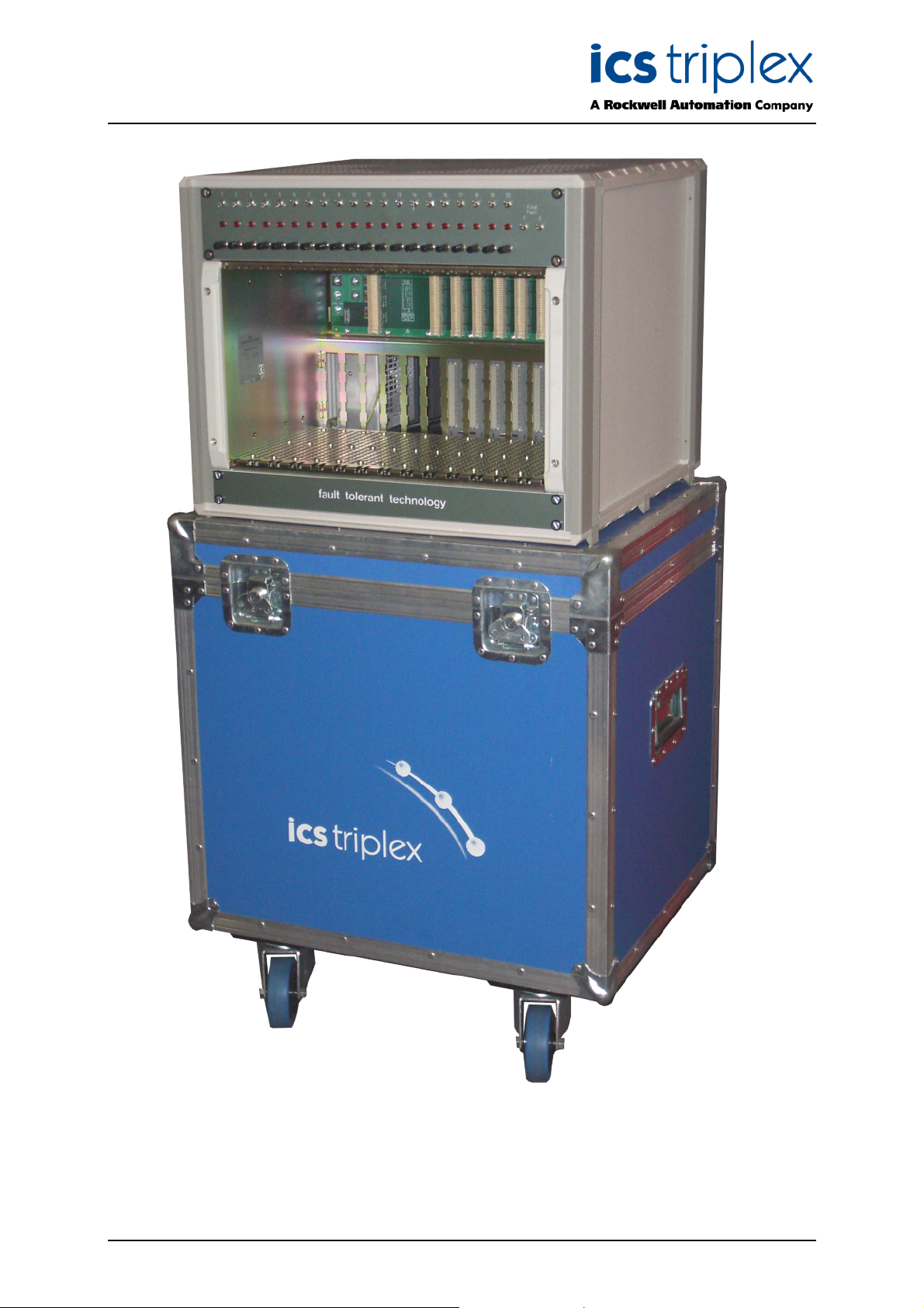
Figure 1 Photo of Demonstration Unit
Issue 1 Feb 06 PD-T8141 3
Page 4

Trusted
TM
Demonstration Unit T8141
Table of Contents
1. Description......................................................................................................................................7
1.1. Communications Ports ...................................................................................................................8
2. Installation ......................................................................................................................................9
3. Operation......................................................................................................................................10
4. Communications Connections......................................................................................................11
4.1. Ethernet Ports...............................................................................................................................11
4.1.1. Ethernet Port 0 .............................................................................................................................12
4.1.2. Ethernet Port 1 .............................................................................................................................12
4.2. Serial Ports ...................................................................................................................................13
5. Specifications ...............................................................................................................................14
Figures
Figure 1 Photo of Demonstration Unit ......................................................................................................3
Figure 2 Front Panel with pre-configured slot locations............................................................................7
Figure 3 Rear View - Internal Layout ........................................................................................................8
Figure 4 Analogue Input Connection ......................................................................................................10
Figure 5 Ethernet Connections 0 (HUB) and 1 (PC) ..............................................................................11
Figure 6 RJ45 Connections ....................................................................................................................11
Tabl es
Table 1 Ethernet Port 0 (HUB)................................................................................................................12
Table 2 Ethernet Port 1 (PC) ..................................................................................................................12
Table 3 Serial Port Terminations ............................................................................................................13
Issue 1 Feb 06 PD-T8141 4
Page 5

Trusted
TM
Demonstration Unit T8141
Notice
The content of this document is confidential to ICS Triplex Technology Ltd. companies and their
partners. It may not be given away, lent, resold, hired out or made available to a third party for any
purpose without the written consent of ICS Triplex Technology Ltd.
This document contains proprietary information that is protected by copyright. All rights are reserved.
icrosoft, Windows, Windows 95, Windows NT, Windows 2000, and Windows XP are registered
M
trademarks of Microsoft Corporation.
The information contained in this document is subject to change without notice. The reader should, in
all cases, consult ICS Triplex Technology Ltd. to determine whether any such changes have been
made. From time to time, amendments to this document will be made as necessary and will be
distributed by ICS Triplex Technology Ltd.
Information in this documentation set may be subject to change without notice and does not represent
a commitment on the part of ICS Triplex Technology Ltd.
The contents of this document, which may also include the loan of software tools, are subject to the
confidentiality and other clause(s) within the Integrator Agreement and Software License Agreement.
No part of this documentation may be reproduced or transmitted in any form or by any means,
electronic or mechanical, including photocopying and recording, for any purpose, without the express
written permission of ICS Triplex Technology Ltd.
Disclaimer
The illustrations, figures, charts, and layout examples in this manual are intended solely to illustrate the
text of this manual.
The user of, and those responsible for applying this equipment, must satisfy themselves as to the
acceptability of each application and use of this equipment.
This document is based on information available at the time of its publication. While efforts have been
made to be accurate, the information contained herein does not purport to cover all details or variations
in hardware or software, nor to provide for every possible contingency in connection with installation,
operation, or maintenance. Features may be described herein which are present in all hardware or
software systems. ICS Triplex Technology Ltd. assumes no obligation of notice to holders of this
document with respect to changes subsequently made.
ICS Triplex Technology Ltd. makes no representation or warranty, expressed, implied, or statutory with
respect to, and assumes no responsibility for the accuracy, completeness, sufficiency, or usefulness of
the information contained herein. No warranties of merchantability or fitness for purpose shall apply.
Issue 1 Feb 06 PD-T8141 5
Page 6

Trusted
TM
Demonstration Unit T8141
Revision and Updating Policy
All new and revised information pertinent to this document shall be issued by ICS Triplex Technology
Ltd. and shall be incorporated into this document in accordance with the enclosed instructions. The
change is to be recorded on the Amendment Record of this document.
Precautionary Information
WARNING
Warning notices call attention to the use of materials, processes, methods, procedures or limits which
must be followed precisely to avoid personal injury or death.
CAUTION
Caution notices call attention to methods and procedures which must be followed to avoid damage to
the equipment.
Notes:
Notes highlight procedures and contain information to assist the user in the understanding of the
information contained in this document
Warning
RADIO FREQUENCY INTERFERENCE
Most electronic equipment is influenced by Radio Frequency Interference (RFI). Caution should be
exercised with regard to the use of portable communications equipment around such equipment.
Signs should be posted in the vicinity of the equipment cautioning against the use of portable
communications equipment.
MAINTENANCE
Maintenance must be performed only by qualified personnel, otherwise personal injury or death, or
damage to the system may be caused.
Caution
HANDLING
Under no circumstances should the module housing be removed.
Associated Documents
Product Descriptions (PD) provide product specific information.
The Safety Manual contains the recommended safety requirements for the safety system design.
The PD8082B – Toolset Suite provides specific guidance on system configuration and application
generation.
The Operator and Maintenance Manual contains general guidelines on maintenance and diagnostic
procedures.
PD-8100 gives details of the chassis design, which is the heart of the Demonstration Unit.
For technical support email: support@icstriplex.com
Issue 1 Feb 06 PD-T8141 6
Page 7

Trusted
TM
Demonstration Unit T8141
1. Description
Figure 2 Front Panel with pre-configured slot locations
This simulation panel is designed to assist with demonstrating simple systems for sales or training. It is
possible to fit any I/O module into the eight I/O slots as required, if the field cable connectors are
moved or removed.
TM
The Trusted
• 20 switches for driving Digital Inputs (connected to slots 1 and 2 by default)
• 20 lamps for displaying Digital Outputs (connected to slots 5 and 6 by default)
• 2 switches for simulating short circuits on output channels 19 and 20
• 20 potentiometer knobs for driving Analogue Inputs (connected to slots 3 and 4 by default)
The processor slots and the three wired simulation slots are designed to allow module hot swaps,
using double width hoods for the field connections. A single slot field cable is provided for the
Communications Module, which is wired to terminals in the rear of the panel. This provides two
Ethernet ports on RJ45 connectors (one has a crossover for direct PC connection), two RS232 ports
on terminals and two RS422/RS485 full duplex ports on terminals.
Note that a Maintenance communications cable TC-304-01 is provided, but that Trusted
not provided with the Demonstration Unit.
Issue 1 Feb 06 PD-T8141 7
Demonstration Unit is equipped with the following simulation devices:
TM
modules are
Page 8

Trusted
TM
Demonstration Unit T8141
Figure 3 Rear View - Internal Layout
1.1. Communications Ports
The following ports on the Communications Module are connected at the rear of the unit:
• Ethernet port 0 via RJ45 (wired for connection to a Hub)
• Ethernet port 1 via RJ45 (wired for connection directly to a PC)
• Serial port 1 via terminals (RS232)
• Serial port 2 via terminals (RS232)
• Serial port 3 via terminals (RS422/485 full duplex)
• Serial port 4 via terminals (RS422/485 full duplex)
Issue 1 Feb 06 PD-T8141 8
Page 9

Trusted
TM
Demonstration Unit T8141
2. Installation
The Demonstration Unit is provided with a British three-pin mains lead to fit the IEEE mains socket on
he rear of the chassis. This must be replaced as appropriate for the local mains connections. A 13A
t
mains lead is recommended, because the mains input circuit breaker is rated at 10A. The unit will
require much less power in operation.
The module field connectors are connected to the chassis in the slots shown in Figure 2. To remove
these connectors, first remove the modules. Press the button on the bottom of the connector and slide
it downwards. To fit a connector, again remove the modules. Insert the connector into the slots slightly
below its final position, and slide it up until it clicks.
To use the Ethernet ports, connect an Ethernet patch lead to the rear port and to the PC or hub. Note
that port 0 is wired for connection via a hub and port 1 is wired for direct connection to a PC.
The operation and configuration of the modules is described in Product Descriptions PD-8082B, PD8110B, PD-8151B and the appropriate I/O module PD. The basic steps are as follows:
1. Insert a Processor T8110B into the left slot.
2. Insert the I/O modules as required.
3. Insert a T8151B Communications Module if required.
4. Power the Unit.
5. Prepare a System.INI configuration specifying the selected modules. This should include
Ethernet IP addresses for the Communications Module if these are required.
6. Download the System.INI configuration to the Processor using the TC-304-01 maintenance
lead.
7. Design a project in the Toolset, specifying the selected modules and application.
8. Compile the project with the Motorola compiler option.
9. Download the application to the Unit. This may be performed using the TC-304-01
maintenance lead or via the Ethernet port configured in step 5 above.
10. Turn the Unit off and on to load the System.INI file to the I/O modules.
Issue 1 Feb 06 PD-T8141 9
Page 10

Trusted
TM
Demonstration Unit T8141
3. Operation
The Digital Input switches operate inputs 1 to 20 as marked. Pushing the switch down connects the
nput to 24V (logic 1) and pushing the switch up will allow the input to return to 0V (logic 0).
i
The Digital Output lamps indicate channels 1 to 20 as marked. They are designed for 24V operation
and are each fitted with 390R 2.5W resistors in parallel to increase the load above the line monitor
open-circuit threshold. For lamps 19 and 20, Field Fault switches 1 and 2 respectively will connect a
short circuit across the lamp if pressed down, for demonstration of line fault conditions.
The Analogue Input potentiometer knobs control channels 1 to 20 as marked. They are connected to
provide a potential divider to the analogue input. Each has a 27K 0.25W resistor connected from the
24V supply, in series with the 10K track of the potentiometer, to zero volts. The analogue input voltage
may be adjusted between the zero volt rail and approximately 6.5 volts, to simulate the full range of 022mA inputs with over-range excess.
24V
27K
10K Input
Figure 4 Analogue Input Connection
Two terminals (11 and 12) at the bottom of the 24Vdc fuse distribution block provide a 1A 24V dc
auxiliary power supply, for supplying interface equipment or other low current devices. Terminal 11 is
24V dc and terminal 12 is 0V dc.
Issue 1 Feb 06 PD-T8141 10
Page 11

Trusted
TM
Demonstration Unit T8141
4. Communications Connections
4.1. Ethernet Ports
Figure 5 Ethernet Connections 0 (HUB) and 1 (PC)
Figure 6 RJ45 Connections
Issue 1 Feb 06 PD-T8141 11
Page 12

Trusted
TM
Demonstration Unit T8141
4.1.1. Ethernet Port 0
This port is wired for connection via a hub.
RJ45 Pin
1 TD+
2 TD-
3 RD+
6 RD-
Table 1 Ethernet Port 0 (HUB)
4.1.2. Ethernet Port 1
This port is wired for direct connection to a PC.
RJ45 Pin
1 RD+
2 RD-
3 TD+
6 TD-
Table 2 Ethernet Port 1 (PC)
Function
Function
Issue 1 Feb 06 PD-T8141 12
Page 13

Trusted
TM
Demonstration Unit T8141
4.2. Serial Ports
COMMS Terminal Block Pin Port Function
1 Tx
2 Rx
3
4 Tx
5 Rx
6
7 Rx/TxB
8 Rx/TxA
9 TxB
10 TxA
11
12 Rx/TxB
13 Rx/TxA
14 TxB
15 TxA
16
Table 3 Serial Port Terminations
1 (RS232)
GND
2 (RS232)
GND
3 (RS422/485)
GND
4 (RS422/485)
GND
Issue 1 Feb 06 PD-T8141 13
Page 14

Trusted
TM
Demonstration Unit T8141
5. Specifications
Supply Range
Current Protection
Incoming Circuit Breaker 10A double pole
24V Distribution Circuit Breaker 16A single pole
Chassis Supply Fuses (F1,F2) 16A 380V (Weidmuller SAKS4)
Fan Tray (F3), DI (F4),AI (F5) Fuses 1A 70V (WSI6 25mm)
DO (F6) Fuse 2A 70V (WSI6 25mm)
Auxilliary Supply (F10) Fuse 1A 70V (WSI6 25mm)
Operating Temperature
Non-operating Temperature
Operating Humidity
Environmental Specifications
Dimensions (without flight case)
Height
Width
Depth
Weight (with flight case, typical modules)
100V to 240V ac
-5°C to 60°C (23°F to 140°F)
-25°C to 70ºC (-13°F to 158°F)
5 to 95% RH
Refer to Document 552517
534 mm (21ins)
430 mm (16.9ins)
500 mm (19.7ins)
65 kg (140lbs.) nominal
Issue 1 Feb 06 PD-T8141 14
Page 15

Trusted
TM
Demonstration Unit T8141
This page is intentionally blank
Issue 1 Feb 06 PD-T8141 15
Page 16

 Loading...