

Page 1

TrustedTM
PD-T813X
Trusted
Introduction
TM
Processor Interface Adaptor
This document provides general information for the TrustedTM Processor Interface Adaptor T813x.
The Adaptor provides easy access to the communications ports of the Trusted
(T8110B) in the Controller Chassis for DCS and other links. The unit is also used to enable a number
of extended facilities available on the Trusted
IRIG B time synchronisation signals, enabling the use of Dual (‘enhanced’) Peer to Peer and enabling
the Trusted
Features
TM
system to become Modbus Master.
• Allows easy access for external systems to communicate with a Trusted
Processor.
• Easy installation (connects directly to the rear of the Controller Chassis).
• Two RS422/485 configurable 2 or 4 wire connections.
• One RS422/485 2 wire connection.
• Fault/fail connections for Active and Standby Processors.
• Processor diagnostics connection.
• PSU shutdown monitor connections.
• Enables IRIG B122 and IRIG B002 time synchronisation signals.
• Enables Modbus Master on the Trusted
• Enables ICS2000 to Trusted
TM
TM
TMR Processor including facilities for the reception of
TM
Interface
Communications Interface.
M
T
TMR Processor
TM
TMR
Issue 4 Sep 07 PD-T813X 1
Page 2

Trusted
Issue Record
Issue
Number Date Revised by Technical CheckAuthorised by Modification
2 Sep 05 J W Clark Format
3 Aug 06 N Owens I Vince P Stock Dual Peer to Peer
4 Sep 07 N Owens I Vince P Stock Port purposes
TM
Interface Adapter T813X
Issue 3 Aug 06 PD-T813X 2
Page 3

Trusted
TM
Interface Adapter T813X
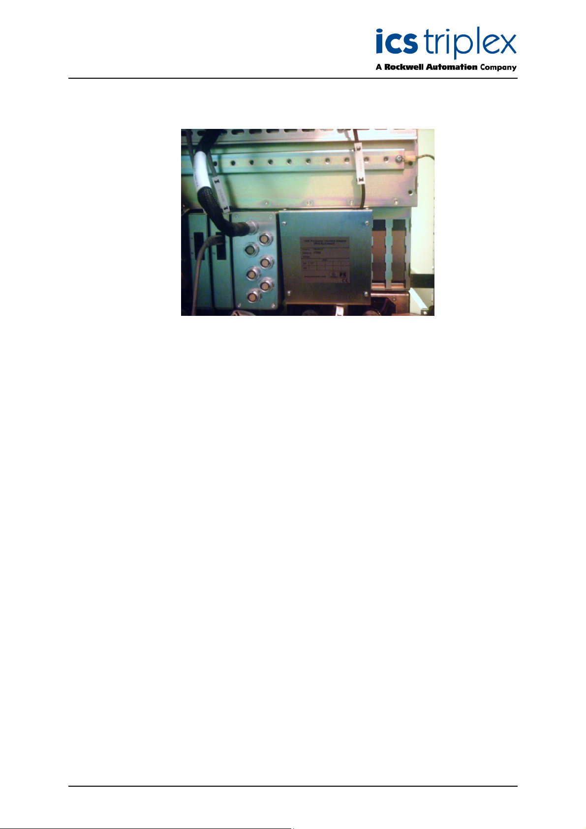
Figure 1 Photo T813X
Issue 3 Aug 06 PD-T813X 3
Page 4

Trusted
TM
Interface Adapter T813X
Table of Contents
1. Description......................................................................................................................................7
1.1. Processor Interface Connector (SK1)..........................................................................................8
1.2. Fault/Fail Connectors (J2 & J3) ...................................................................................................9
1.3. Diagnostic Connector (J4) ...........................................................................................................9
1.4. PSU Shutdown Monitor Connector (J6).......................................................................................9
1.5. Serial Port 1 (Diagnostic) Connectors (J7 and J12) ..................................................................10
1.6. Serial Ports 2 and 3 Connectors (J8 to J11) ..............................................................................10
1.7. IRIG B Connector (J5) ...............................................................................................................10
1.8. Mating Connectors.....................................................................................................................11
2. Installation ....................................................................................................................................12
3. Input Configuration .......................................................................................................................13
3.1. Serial Ports ................................................................................................................................13
3.2. IRIG-B Ports...............................................................................................................................13
4. Available Options..........................................................................................................................14
5. Specifications ...............................................................................................................................15
Figures
Figure 1 Photo T813X............................................................................................................................. 3
Figure 2 Adaptor Layout ......................................................................................................................... 7
Figure 3 Correct Installation Position.................................................................................................... 12
Tab l es
Table 1 Connector SK1 Pinout ............................................................................................................... 8
Table 2 Fault/Fail Connectors................................................................................................................. 9
Table 3 Diagnostic Connector ................................................................................................................ 9
Table 4 PSU S/D Monitor Connectors .................................................................................................... 9
Table 5 Serial Port 1 Diagnostic Connectors........................................................................................ 10
Table 6 Serial Ports 2 & 3 Connectors ................................................................................................. 10
Table 7 IRIG B Connector .................................................................................................................... 10
Table 8 Mating Connectors................................................................................................................... 11
Table 9 Available Options..................................................................................................................... 14
Issue 3 Aug 06 PD-T813X 4
Page 5

Trusted
TM
Interface Adapter T813X
Notice
The content of this document is confidential to ICS Triplex Technology Ltd. companies and their
partners. It may not be given away, lent, resold, hired out or made available to a third party for any
purpose without the written consent of ICS Triplex Technology Ltd.
This document contains proprietary information that is protected by copyright. All rights are reserved.
icrosoft, Windows, Windows 95, Windows NT, Windows 2000, and Windows XP are registered
M
trademarks of Microsoft Corporation.
The information contained in this document is subject to change without notice. The reader should, in
all cases, consult ICS Triplex Technology Ltd. to determine whether any such changes have been
made. From time to time, amendments to this document will be made as necessary and will be
distributed by ICS Triplex Technology Ltd.
Information in this documentation set may be subject to change without notice and does not represent
a commitment on the part of ICS Triplex Technology Ltd.
The contents of this document, which may also include the loan of software tools, are subject to the
confidentiality and other clause(s) within the Integrator Agreement and Software License Agreement.
No part of this documentation may be reproduced or transmitted in any form or by any means,
electronic or mechanical, including photocopying and recording, for any purpose, without the express
written permission of ICS Triplex Technology Ltd.
Disclaimer
The illustrations, figures, charts, and layout examples in this manual are intended solely to illustrate the
text of this manual.
The user of, and those responsible for applying this equipment, must satisfy themselves as to the
acceptability of each application and use of this equipment.
This document is based on information available at the time of its publication. While efforts have been
made to be accurate, the information contained herein does not purport to cover all details or variations
in hardware or software, nor to provide for every possible contingency in connection with installation,
operation, or maintenance. Features may be described herein which are present in all hardware or
software systems. ICS Triplex Technology Ltd. assumes no obligation of notice to holders of this
document with respect to changes subsequently made.
ICS Triplex Technology Ltd. makes no representation or warranty, expressed, implied, or statutory with
respect to, and assumes no responsibility for the accuracy, completeness, sufficiency, or usefulness of
the information contained herein. No warranties of merchantability or fitness for purpose shall apply.
Issue 3 Aug 06 PD-T813X 5
Page 6

Trusted
TM
Interface Adapter T813X
Revision and Updating Policy
All new and revised information pertinent to this document shall be issued by ICS Triplex Technology
Ltd. and shall be incorporated into this document in accordance with the enclosed instructions. The
change is to be recorded on the Amendment Record of this document.
Precautionary Information
WARNING
Warning notices call attention to the use of materials, processes, methods, procedures or limits which
must be followed precisely to avoid personal injury or death.
CAUTION
Caution notices call attention to methods and procedures which must be followed to avoid damage to
the equipment.
Notes:
Notes highlight procedures and contain information to assist the user in the understanding of the
information contained in this document
Warning
RADIO FREQUENCY INTERFERENCE
Most electronic equipment is influenced by Radio Frequency Interference (RFI). Caution should be
exercised with regard to the use of portable communications equipment around such equipment.
Signs should be posted in the vicinity of the equipment cautioning against the use of portable
communications equipment.
MAINTENANCE
Maintenance must be performed only by qualified personnel, otherwise personal injury or death, or
damage to the system may be caused.
Caution
HANDLING
Under no circumstances should the module housing be removed.
Associated Documents
Product Descriptions (PD) provide product specific information.
The Safety Manual contains the recommended safety requirements for the safety system design.
The PD8082B – Toolset Suite provides specific guidance on system configuration and application
generation.
The Operator and Maintenance Manual contains general guidelines on maintenance and diagnostic
procedures.
For technical support email: support@icstriplex.com
Issue 3 Aug 06 PD-T813X 6
Page 7

Trusted
TM
Interface Adapter T813X
1. Description
The TrustedTM Processor Interface Adaptor T813x is designed to be connected directly to the rear of a
rusted
T
communications connection interface between the Trusted
The Adaptor also provides the option of connecting IRIG B time synchronisation signals to the
Processor. Connection between the Adaptor and the Trusted
M
T
MR Processor position in a Trusted
T
M
T
ontroller Chassis T8100. The Adaptor provides a
C
M
T
TMR Processor and remote systems.
M
T
TMR Processor is via two 48-way
DIN41612 E-type connectors (SK1), one each for connection to the Active and Standby Processors.
Figure 2 shows the physical layout of serial port, diagnostics and IRIG B connectors on the Adaptor
pcb.
Figure 2 Adaptor Layout
The Adaptor comprises a printed circuit board (pcb) on which the communications ports, IRIG B
connectors and both SK1 sockets (connectors to the Active/Standby Trusted
TM
TMR Processors) are
mounted. The Adaptor is contained within a metal enclosure and is designed to be clipped onto the
appropriate connector at the rear of the Controller Chassis. Release buttons are provided to enable
the Adaptor to be disconnected.
The communications port available at the Adaptor are RS422/RS485 2 wire on Port 1, and
RS422/RS485 2 or 4 wire on Ports 2 and 3.
An earth point is provided on the pcb so that the Chassis earth of the Processor will be connected to
the shell of the Adaptor and module rack earth. It is an important safety and ESD requirement that the
equipotential bonding is connected and maintained.
Issue 3 Aug 06 PD-T813X 7
Page 8

Trusted
TM
Interface Adapter T813X
1.1. Processor Interface Connector (SK1)
SK1 is a 48-way DIN41612, E-type connector.
Pin
10 5V_D Serial Port 1 A IRIG B122+
12 DATA_OUT 0V Port 2 IRIG B122-
14 ENABLE Serial Port 2 B TX Reserved
16 DATA_IN Serial Port 2 A TX Reserved
18 CLK Serial Port 2 B RX/TX IRIG B002-
20 0V Serial Port 2 A RX/TX IRIG B002+
22 Chassis GND 0V Port 3 Chassis GND
24 Chassis GND Serial Port 3 B TX Chassis GND
26 Chassis GND Serial Port 3 A TX Chassis GND
28 24V PSU 1 LV
30 24V PSU 2 LV
32 24V Return 24V Return 24V Return
CONNECTOR SK1 PINOUT
A B C
2 Fault Relay (NC) DIAG_RTN Failed Relay (NC)
4 Fault Relay
(Common)
6 Fault Relay (NO) 0V Port 1 Failed Relay (NO)
8 N.C. Serial Port 1 B N.C.
Warning
Warning
DIAG_IN_1 Failed Relay
(Common)
Serial Port 3 B RX/TX 24V PSU 1 Shutdown
Serial Port 3 A RX/TX 24V PSU 2 Shutdown
Table 1 Connector SK1 Pinout
Issue 3 Aug 06 PD-T813X 8
Page 9

Trusted
TM
Interface Adapter T813X
1.2. Fault/Fail Connectors (J2 & J3)
J2 and J16 are Phoenix contact 2.5mm pitch connectors.
Pin Service
1 FAULT_n_NC
2 FAULT_n_COMMON
3 FAULT_n_NO
4 FAIL_n_NC
5 FAIL_n_COMMON
6 FAIL_n_NO
Table 2 Fault/Fail Connectors
Note: n=1 for connector J2 and 2 for connector J3 providing fault and fail connections for the Active
and Standby processors respectively. FAULT opens on any system fault which sets the
Processor Healthy LED red. FAIL opens on shutdown of the Processor.
1.3. Diagnostic Connector (J4)
J4 is a Phoenix contact 2.5mm pitch connector. This port is not for operational use.
Pin Service
1 DIAG_RTN
2 DIAG_IN_1
Table 3 Diagnostic Connector
1.4. PSU Shutdown Monitor Connector (J6)
J6 is Phoenix contact 2.5mm pitch connector. These two system inputs are made available to the
application on the Processor’s complex I/O equipment definition. The inputs expect volt-free contacts
to the RTN pin.
Pin Service
1 24V_PSU1_SHUTDOWN
2 24V_PSU2_SHUTDOWN
3 24V_RTN
Table 4 PSU S/D Monitor Connectors
Issue 3 Aug 06 PD-T813X 9
Page 10

Trusted
TM
Interface Adapter T813X
1.5. Serial Port 1 (Diagnostic) Connectors (J7 and J12)
J7 and J12 are Phoenix 2.5mm pitch connectors.
Pin Service
1 0V
2 SERIAL_1_B
3 SERIAL_1_A
Table 5 Serial Port 1 Diagnostic Connectors
1.6. Serial Ports 2 and 3 Connectors (J8 to J11)
These are Phoenix 2.5mm pitch connectors.
Pin Service
1 0V
2 SERIAL_TX_B
3 SERIAL_TX_A
4 SERIAL_RX/TX_B
5 SERIAL_RX/TX_A
Table 6 Serial Ports 2 & 3 Connectors
1.7. IRIG B Connector (J5)
J5 is a Phoenix 2.5mm pitch connector.
Pin Service
1 IRIG B122+
2 IRIG B122-
3 IRIG B002-
4 IRIG B002+
Table 7 IRIG B Connector
Issue 3 Aug 06 PD-T813X 10
Page 11
Trusted
TM
Interface Adapter T813X
1.8. Mating Connectors
The following table lists the connectors required to mate with the Trusted
Adaptor.
Connector Phoenix Contact Part No ICS Part No No of Ways
J2,J3 18 81 36 7 3JX072 6
J4 18 81 32 5 3JX073 2
J5 18 81 34 1 3JX074 4
J6,J7,J12 18 81 33 8 3JX075 3
J8,J9,J10,J11 18 81 35 4 3JX076 5
Table 8 Mating Connectors
M
T
Processor Interface
Issue 3 Aug 06 PD-T813X 11
Page 12
Trusted
TM
Interface Adapter T813X
2. Installation
Figure 3 Correct Installation Position
The adapter should be fitted on the rear of the chassis behind the processor slots, as shown above.
The two connectors should fit into the third and sixth slots from the right, where the processor
connectors will fit. In the correct position, two empty slots will be visible on the right. Insert the adapter
into position about 5mm lower than its final position, and ensure it is slotted in on both sides. Raise the
adapter upwards until the retaining clips click into place.
Issue 3 Aug 06 PD-T813X 12
Page 13

Trusted
TM
Interface Adapter T813X
3. Input Configuration
3.1. Serial Ports
The serial ports connectors are arranged so that multi-drop RS422/485 connections can be easily
configured. J7, J8 and J10 together with LK1, LK2 and LK3 form the basic terminations for ports 1, 2
and 3 respectively.
For a single point connection the termination would be made to the relevant connector and its
corresponding link would be fitted. For a multi-drop connection the ‘incoming’ connections would be
made to the connections listed above and the ‘outgoing’ to J12, J9 or J11 for ports 1 to 3 respectively.
This time however, the link will be removed as only the last connection on a multipdrop chain should be
terminated.
The provision of the two connectors for each serial port will enable quicker configuration of serial
cabling as there is now no need to terminate two cables onto the same connector. The links LK1 to
LK3 provide the serial ports with an easy way to add 120 ohm AC termination onto the receivers
extremely close to the receiving devices.
The 4 wire serial ports 2 and 3 have connectors that are pin compatible with those used on the
Trusted
Serial connections should use screened twisted pair cable with the A-B signals connected as a pair.
The screen should be connected to chassis ground at one end only. Some equipment may require a
common 0V connection in order to operate correctly, the 0V on the connector should be connected to
0V on the other equipment to facilitate this.
Further information on serial port configuration can be found in the standards listed below:
EIA/TIA-422-B
EIA-485
CCITT V.11
TM
Communications Interface Termination Unit (T8153).
3.2. IRIG-B Ports
The IRIG-B002 input is a pulse width modulated signal ant 100bits/s and uses RS422 voltage levels.
Connection to this port should be by twisted pair cable. A 120 ohm termination (R13) is permanently
provided on the module. For multi-drop IRIG configurations, the resistor must be removed on all but
the last interface adaptor.
The IRIG-B122 input is a 1KHz amplitude modulated signal where the modulating signal has the same
format as IRIG-B002. The peak amplitude (mark) of the input signal is nominally 1V to 6V into 600R.
The Trusted
B122 is normally provide via co-axial cable although any suitable medium would be acceptable.
TM
TMR Processor is able to receive signal in the range 0.25V PK-PK to 10V PK-PK. IRIG-
Further information on IRIG configuration can be found in the standards listed below:
Range Commanders Council IRIG STANDARD 200-98
IEEE Std 1344-1995 Annex F.2
Issue 3 Aug 06 PD-T813X 13
Page 14

Trusted
TM
Interface Adapter T813X
4. Available Options
The following table lists the variants of the TrustedTM Processor Adaptor Unit and the TrustedTM TMR
rocessor options that can be made available by using them. All the variants below will enable the use
P
of Dual (‘enhanced’) Peer to Peer with other Trusted
its associated data transfer I/O definitions. The Interface Adapter will not enable Dual Peer to Peer
communication with Plantguard systems.
Variant Options Enabled
T8131
ICS 2000 IRIG-B and Modbus Master
Enables ICS2000, IRIG-B time signal decode and Modbus Master operation.
Table 9 Available Options
M
T
systems, using the dxpnc40 I/O definition and
Issue 3 Aug 06 PD-T813X 14
Page 15

Trusted
TM
Interface Adapter T813X
5. Specifications
Ports
Port 1
Ports 2 and 3
IRIG B
Operating Temperature
Non-operating Temperature
Operating Humidity
Environmental Specifications
Dimensions
Height:
Width:
Depth:
Weight
RS422/485
RS422/485
IRIG B122 and IRIG B002 on a single
connector
0
C to 600C (230F to 1400F)
-5
0
C to 700C (-130F to 1580F)
-25
5 to 95% RH
Refer to Document 552517
138mm (5.43ins)
120mm (4.72ins)
108mm (4.25ins)
877gms (1.93lbs.)
Issue 3 Aug 06 PD-T813X 15
Page 16

 Loading...