

Page 1
SDS-T812X
TM
Trusted
Industrial Control System
Trusted
TM
Processor Interface Adaptor Module - T812X
DESCRIPTION
The Trusted
the communications ports of the Trusted
Controller Chassis for Peer to Peer communications, DCS and other links,
networked PCs etc. The Adaptor also supports fault/fail and diagnostics
connections to the Processor, and connection facilities for IRIG B time
Synchronisation facilities, as well as enabling the user of Modbus Master
facilities on the T8151 Communication Interface Card.
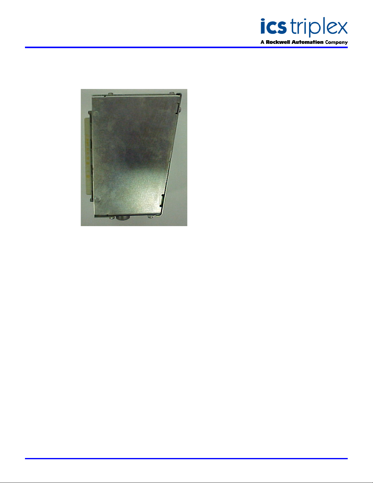
The Adaptor comprises a printed circuit board (PCB) on which the
communications ports are mounted. The PCB also supports two 48-way
DIN41612 E-type connectors which enables the Adaptor to be plugged into
the Trusted
and Standby) at the rear of the Trusted
communications ports available from the Adaptor are RS485 (Port 1) and
RS422/485 (Ports 2 and 3). The Ports are accessed via Phoenix contact
2.5mm pitch connectors.
Fault/fail, diagnostic and PSU shutdown monitor, and IRIG B time
Synchronisation signals are also available via Phoenix connectors.
A complete set of connectors mentioned above are allocated to both the
Active and Standby processors.
Termination resistors for RS422/485 communications are selectable via
links. These are mounted on the PCB and are the only configurable items
which require setting up before using the Adaptor.
TM
Processor Interface Adaptor T812X provides easy access to
TM
TMR Processor Module input/output (I/O) connectors (Active
TM
TMR Processor in the TrustedTM
TM
Controller Chassis. The
When the Adaptor is plugged into
the I/O connector on the rear of
the Trusted
it is mechanically latched in
position. Release buttons are
provided to enable the user to
unplug the Adaptor as required.
M
T
Controller Chassis,
FEATURES
Allows easy access for
external systems to
communicate with a
Trusted
TM
System
Easy installation (connects
directly onto the I/O
connector at the rear of the
processor)
Two RS422/485
connections
One RS485 connection
Fault/fail connections for
Active and Standby
Processors
Processor diagnostics
connection
PSU shutdown monitor
connections
Connection facilities for
IRIG B122 and IRIG B002
time Synchronisation
signals
Modbus Master enabling of
the T8151B Communication
Interface Card
Issue 5 Jan 2006
Page 2
SDS-T812X
Trusted
TM
Industrial Control System
Trusted
TM
Processor Interface Adaptor - T812X
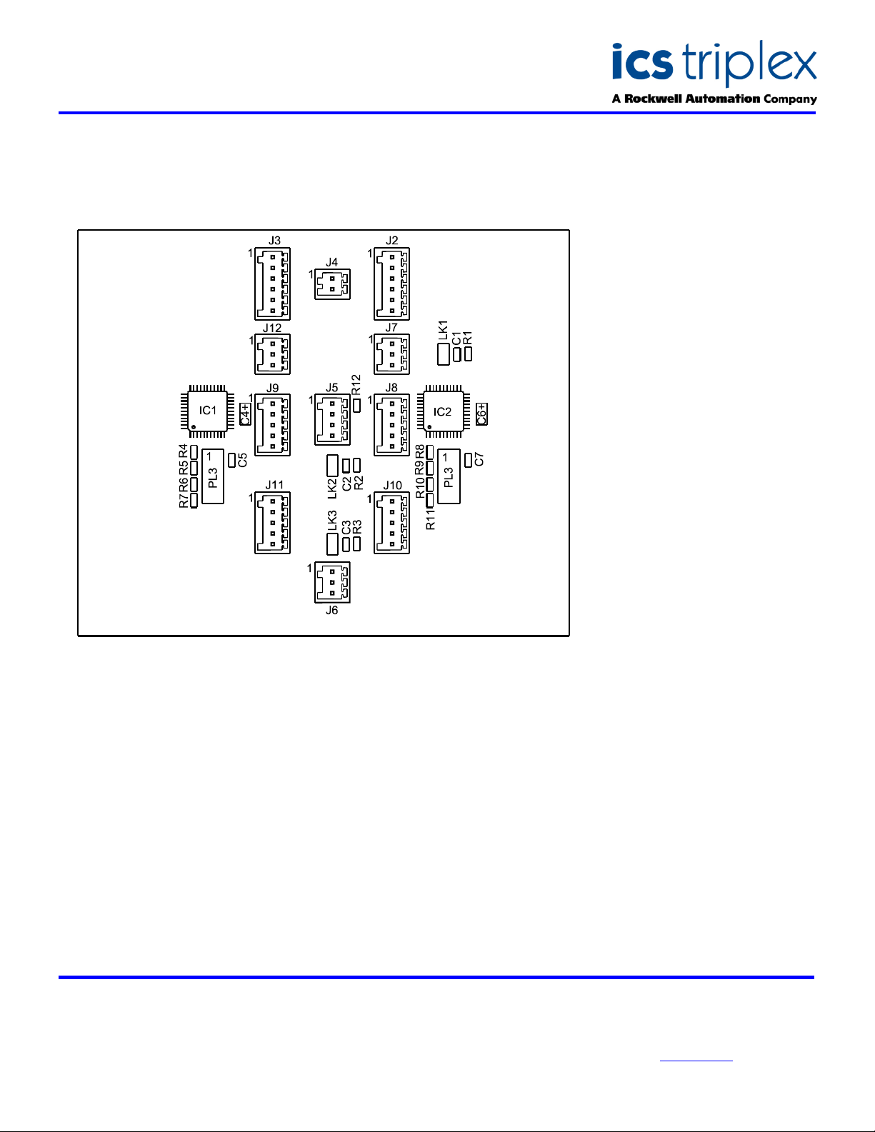
ASSEMBLY LAYOUT
ELECTRICAL SPECIFICATION
Serial Ports
Active and Standby
Connections
Active and Standby
AVAILABLE OPTIONS
T8120
T8121
T8122
T8123
1-off RS485
2-off RS422/485
1-off fault/fail
1-off diagnostic
1-off PSU shutdown monitor
1-off IRIG B (122 and 002 on the same
connector)
Basic Module
IRIG-B
Modbus Master
IRIG-B and Modbus Master
MECHANICAL
SPECIFICATION
Dimensions (HxWxD):
138mm x 120mm x
108mm
(5.43ins x 4.72ins x
4.25ins)
Weight:
877gms
(1.93lbs)
ENVIROMENTAL
Operating Temperature:
-5°C to 60°C
(23°F to 140°F)
Operating Humidity:
5 to 95%, noncondensing
Vibration:
10 to 57Hz ±0.075mm
57 to 150Hz 1.0g
Shock:
15g, ½ sine wave, 11ms
EMI (IEC 801):
ESD
Air discharge to 15kV
Contact discharge to 8kV
Radiated Fields
10V/m, 27MHz to
500MHz
Transients and Bursts
2kV, 2.5kHz for
t=60 seconds
ICS Triplex
Technical data sheets are intended for
information and guidance. The Company
has a policy of continual product
development an improvement.
Specifications are subject to change
without notice. For latest information, visit
our Websi te:- www.icstriplex. com
 Loading...