

Page 1

8000 SERIES TMR SYSTEM
SAFETY MANUAL
T8094
ISSUE 27 – JUNE 2013
Page 2

SAFETY MANUAL
Copyright © Rockwell Automation 1998-2013
Printed in England
Doc Number T809 4
Issue 27 – J u n e 2013 Page ii
Page 3

SAFETY MANUAL
This page intentionally blank
Doc Number T809 4
Issue 27 – J u n e 2013 Page iii
Page 4

SAFETY MANUAL
Issue Record and Record of Amendments
Issue Changes
Number Date
Issue 1 Sep 99
Issue 2 Sep 01
Issue 3 Nov 01
Issue 4 Mar-02
Issue 5 Mar-02
Issue 6 May-02
Issue 7 Jan-03
Issue 8 Jan-03
Issue 9 May-03
Issue 10 May-03
Issue 11 May-03
Issue 12
Issue 13
Issue 14
Issue 15 Mar-04
Issue 16 Nov 04
Issue 17 Nov 05
Issue 18 July 06
Issue 19
Initial Issue
Updated to reflect re-certification as of September, 2001
Updated to reflect 3.0 certification.
Updated to add new logo
Updated to correct table and figure numbering.
Updated to reflect 3.1 certification.
Updated to reflect 3.2 certification.
Updated to reflect EN 60204 stop categories. Reworded 3.5.1.2
Added IEC 61508, EN54, NFPA 85 and HFPA 86 requirements
Updated to reflect TUV comments
System release 3.3
Not released
Updated Section 3.12.11 For Intelligent Update
Added 3.7.1.6 & updated 3.22; System Release 3.4
Added Appendix B – Triguard (SC300e) support ; Added Application and
System Configuration archive to 3.12.1 and 3.12.2.; Added 8472 Output
Module to Table 5; Reworded 2.2.1.10.3 & 3.2.4; Removed item 4 from
section 3.13.3; Corrected reference in 3.11.3 to specify section 5; Added
“Grey Channel” to glossary; Corrected 3.6.2 paragraph 2 to refer to the
correct section.; 3.7.2 added ‘companion slot’ to a. and removed ‘pair’
from b.
Updated to incorporate TUV comments to release 3.41; Record of
amendments for issue 15 had incorrect table reference for 8472 Output
module; Previously unlabelled figures and tables given references in
issue 15 and hence figure and table numbering changed.; Some points in
checklist 4.2.1 were changed in error and have been corrected in issue
16
Added T8442 Module (Table 6). Added T8424 Module (Table 4). Added
Enhanced Peer to Peer (Table 3 & section 3.10).; Updated Table 10,
forced air temperatures.; Changed suggested Global Protection to level 8
in table 8.; Corrected reference to NFPA86 & EN54 in 3.2.7 & 3.2.8
Modified table 3 regarding peer to peer
Not released
Doc Number T809 4
Issue 27 – J u n e 2013 P a g e i v
Page 5

SAFETY MANUAL
Issue Changes
Number Date
Issue 20 Feb 09
Issue 21 Oct 09
Issue 22 Nov 12
Issue 23 Nov 12
Issue 24 Jan 13
Issue 25 May 13
Issue 26
Issue 27 June 13
Company logo; master\slave replaced by active\standby; Section 3.7.2
corrected Companion Slot configuration; Added section 6 SYSTEM
SECURITY
Relevant sections revised due to updated standards; NFPA 72:2007,
NFPA 85:2007, NFPA 86:2007.; ICS Triplex Technology replaced with
ICST Triplex
Update for certification of release 3.5.3.
Obsolete – withdrawn.
Details of CS300 migration added in Appendix C.
Instructions for use of autotest management function blocks added in
Appendix C.
Additions and corrections to Appendix C for certification.
Not released.
Draft A – 21 May 2013
Draft B – 23 May 2013
Update for TUV certification of CS300 migration (Appendix C and
section 3.13)
Change of company name in text to Rockwell Automation
Note:
The latest issue of the Safety Manual is available by either:
- contacting icstsupport@ra.rockwell.com
- visiting the TUV website at www.tuv-fs.com/plcics.htm
Doc Number T809 4
Issue 27 – J u n e 2013 P a g e v
Page 6

SAFETY MANUAL
NOTICE
The content of this document is confidential to Rockwell Automation companies and their
partners. It may not be given away, lent, resold, hired out or made available to a third party for
any purpose without the written consent of Rockwell Automation.
This document contains proprietary information that is protected by copyright. All rights are
reserved.
Microsoft, Windows, Windows 95, Windows NT, Windows 2000, and Windows XP are
registered trademarks of Microsoft Corporation.
The information contained in this document is subject to change without notice. The reader
should, in all cases, consult Rockwell Automation to determine whether any such changes have
been made. From time to time, amendments to this document will be made as necessary and
will be distributed by Rockwell Automation.
Information in this documentation set may be subject to change without notice and does not
represent a commitment on the part of Rockwell Automation.
The contents of this document, which may also include the loan of software tools, are subject to
the confidentiality and other clause(s) within the Integrator Agreement and Software License
Agreement.
No part of this documentation may be reproduced or transmitted in any form or by any means,
electronic or mechanical, including photocopying and recording, for any purpose, without the
express written permission of Rockwell Automation.
DISCLAIMER
The illustrations, figures, charts, and layout examples in this manual are intended solely to
illustrate the text of this manual.
The user of, and those responsible for applying this equipment, must satisfy themselves as to
the acceptability of each application and use of this equipment.
This document is based on information available at the time of its publication. While efforts have
been made to be accurate, the information contained herein does not purport to cover all details
or variations in hardware or software, nor to provide for every possible contingency in connection
with installation, operation, or maintenance. Features may be described herein which are
present in all hardware or software systems. Rockwell Automation assumes no obligation of
notice to holders of this document with respect to changes subsequently made.
Rockwell Automation makes no representation or warranty, expressed, implied, or statutory with
respect to, and assumes no responsibility for the accuracy, completeness, sufficiency, or
usefulness of the information contained herein. No warranties of merchantability or fitness for
purpose shall apply.
Doc Number T809 4
Issue 27 – J u n e 2013 P a g e v i
Page 7

SAFETY MANUAL
PREFACE
This Manual contains the recommended Safety Requirements a System Integrator must
consider and implement when designing and building a Safety System using the 8000 series
range of products.
The contents of this Manual have been reviewed by TÜV and all recommendations and
comments made by TÜV have been incorporated.
REVISION AND UPDATING POLICY
All new and revised information pertinent to this document shall be issued by Rockwell
Automation and shall be incorporated into this document in accordance with the enclosed
instructions. The change is to be recorded on the Amendment Record of this document.
PRECAUTIONARY INFORMATION
WARNING
Warning notices call attention to the use of materials, processes, methods, procedures or limits
which must be followed precisely to avoid personal injury or death.
CAUTION
Caution notices call attention to methods and procedures which must be followed to avoid
damage to the equipment.
Notes:
Notes highlight procedures and contain information to assist the user in the understanding of the
information contained in this document
Doc Number T809 4
Issue 27 – J u n e 2013 Page vii
Page 8

MAINTENANCE MUST BE PERFORMED ONLY BY QUALIFIED PERSONNEL.
SAFETY MANUAL
RADIO FREQUENCY INTERFERENCE
MOST ELECTRONIC EQUIPMENT IS INFLUENCED BY RADIO FREQUENCY
INTERFERENCE (RFI). CAUTION SHOULD BE EXERCISED WITH REGARD
TO THE USE OF PORTABLE COMMUNICATIONS EQUIPMENT AROUND
SUCH EQUIPMENT. SIGNS SHOULD BE POSTED IN THE VICINITY OF THE
EQUIPMENT CAUTIONING AGAINST THE USE OF PORTABLE
COMMUNICATIONS EQUIPMENT.
MAINTENANCE
OTHERWISE PERSONAL INJURY OR DEATH, OR DAMAGE TO THE
SYSTEM MAY BE CAUSED.
WARNING
CAUTION
STATIC SENSITIVE DEVICES
MODULES IN THE TMR SYSTEM MAY CONTAIN STATIC SENSITIVE
DEVICES WHICH CAN BE DAMAGED BY INCORRECT HANDLING OF THE
MODULE. THE PROCEDURE FOR MODULE REMOVAL IS DETAILED IN
RELEVANT PRODUCT DESCRIPTIONS AND MUST BE FOLLOWED. ALL
TMR SYSTEMS MUST HAVE LABELS FITTED TO THE EXTERIOR SURFACE
OF ALL CABINET DOORS CAUTIONING PERSONNEL TO OBSERVE ANTISTATIC PRECAUTIONS WHEN TOUCHING MODULES. THESE
PRECAUTIONS ARE DETAILED IN CHAPTER 3 OF THIS PACKAGE.
Doc Number T809 4
Issue 27 – J u n e 2013 Page viii
Page 9

SAFETY MANUAL
1-oo-2 One-out-of-two
1-oo-2D One-out-of-two with diagnostics
2-oo-2 Two-out-of-two
2-oo-3 Two-out-of-three
API Application Program Interface
DIN Deutsche Industrie-Norm (German Industrial Standard)
DIU Diagnostic Interface Utility
EMC Electromagnetic Compatibility
EMI Electromagnetic Interference
EUC Equipment Under Control
FB Function Block
FCR Fault Containment Region
HIFT Hardware Implemented Fault Tolerance
IL Instruction List
I/O Input/Output
IMB Inter-module Bus
LD Ladder Diagram
MMU Memory Management Unit
MTR Mean Time to Repair
PC Personal Computer
PST Process Safety Times
PSU Power Supply Unit
SFC Sequential Function Chart
SFOC Second Fault Occurrence Time
SIL Safety Integrity Levels
ST Structured Text
TMR Triple Modular Redundant
TÜV Technischer Überwachungs-Verein
UPS Uninterruptable Power Supply
ABBREVIATIONS
Doc Number T809 4
Issue 27 – J u n e 2013 P a ge ix
Page 10

h carry related data.
SAFETY MANUAL
Actuators Devices which cause an action (electrical,
Architecture Organisational structure of a computing system
ASCII The American Standard Code for Information
Availability The probability that a system will be able to
Asynchronous A data communications term describing the
Backplane A printed circuit board which supports bussed
Buffer A type of memory in which information is stored
Bus A group of conductors whic
CIE Control Indicating Equipment
Companion Slot Spare (standby) slot position adjacent (to the
Controller A Controller is the heart of any Rockwell
GLOSSARY
mechanical, pneumatic, etc.) to occur when
required within a plant component.
which describes the functional relationship
between board level, device level and system
level components.
Interchange. Uses seven bits to represent 128
characters. Both upper and lower case letters,
numbers, special symbols and a wide range of
control codes are included.
perform its designated function when required
for use – normally expressed as a percentage.
method by which signals between computers
are timed. Although the number of characters
to be sent per second is undefined, the rate at
which a character’s bits are sent is predetermined. Each character is preceded by a
start bit and terminated by a stop bit.
functions to connectors mounted on a printed
circuit board. Plug-in components and modules
are then able to connect to the bus pins.
temporarily during transfer from one device to
another, or one process to another. Normally
used to accommodate the difference in the rate
or time at which the devices can handle the
data.
Micro-based systems have an Address Bus,
Data Bus and a Control Bus.
right) to the slot occupied by the ‘active’
module. The slots are inter-connected to enable
the ‘active’ module to be ‘hot’ replaced as
necessary.
Automation microprocessor based system. It
performs central processing of user application
logic and controls the actions of input and
output hardware, as well as peripheral hardware
such as printers and Visual Display Units.
Doc Number T809 4
Issue 27 – J u n e 2013 Page x
Page 11

SAFETY MANUAL
Discrepancy A discrepancy exists if one or more of the
DRAM Dynamic Random Access Memory. A type of
Element A set of input conditioning, application
Engineering
Workstation
EPROM Erasable Programmable Read Only Memory. A
EUC Equipment Under Control. Equipment,
Fail Safe The capability to go to a pre-determined safe
Fault Tolerance Built-in capability of a system to provide
Field Devices Equipment connected to the field side of the I/O
Firmware Special purpose memory units containing
Fixed Frame An empty fixed metal surround, designed to
FBD Functional Block Diagram. A graphical IEC1131
Grey Channel A non-safety critical communication line
GUI Graphical User Interface
elements disagree.
volatile read/write memory where the data is
stored as a short-life capacitive charge. Though
high density and low cost are a feature of
DRAMs, they require each row address and
hence all data to be refreshed frequently.
processing and output conditioning.
Comprising rugged PC platform fitted with
IEC1131 TOOLSET.
non-volatile storage medium which is
electronically programmed. The EPROM device
may be erased by strong ultra-violet light.
machinery, apparatus or plant used for
manufacturing, process, transportation, medical
or other activities.
state in the event of a specific malfunction.
continued correct execution of its assigned
function in the presence of a limited number of
hardware and software faults.
terminals. Such equipment includes field
wiring, sensors, final control elements and
those operator interface devices hard-wired to
I/O terminals.
software embedded in protected memory
required for the operation of programmable
electronics.
contain 483mm (19”) standard equipment.
language for building complex procedures by
taking existing Functional Blocks from the
IEC1131 library and wiring them together on the
screen.
between two modules that are regarded as
safety critical. Communications sent across a
“grey channel” are viewed as subject to errors
induced by that channel which must be detected
and compensated be the safety related receiver.
Doc Number T809 4
Issue 27 – J u n e 2013 P a ge xi
Page 12

SAFETY MANUAL
Hot Swap Alternative term for Companion Slot
IEC 1131 TOOLSET Software used to configure and program the
8000 series TMR system.
IEC 61508 IEC61508 is an international standard that
covers functional safety, encompassing
electrical, electronic and programmable
electronic systems; hardware and software
aspects.
IEC 61511 IEC61511 is an international standard that
covers functional safety and Safety
Instrumented Systems for the process
industry, encompassing electrical, electronic
and programmable electronic systems,
hardware and software aspects.
EPROM A non-volatile storage medium which is
electronically programmed. The EPROM
device may be erased by strong ultra-violet
light.
IL Instruction List. A low level IEC1131 language,
similar to the simple textual PLC’s language.
Industrial Processor High performance processor for use in non
safety-related applications which can be used
in a simplex or dual-redundant configuration.
Input Module Interface that converts input signals from
external devices into signals that the control
system can utilise.
I/O Input/Output conditioning circuits (as distinct
from the central processing).
I/O Driver Essential software to allow the IEC1131
TOOLSET to configure and program unique
types of TMR system I/O interfaces.
LD Ladder Diagram. An IEC1131 language
composed of contact symbols representing
logical equations and simple actions. The
main function of the ladder diagram is to
control outputs based on input conditions.
MMI Man Machine Interface. The operator’s
window to monitoring and keys, knobs,
switches, Graphical User Interface of the
Operator Workstation, etc. for making
adjustments in the process.
Modbus An industry standard communications
protocol developed by Modicon. Used to
communicate with external devices such as
distributed control systems (DCSs) or operator
interfaces.
M-oo-N m-out-of-n. See Voting System
Module An electronic (generally pluggable) sub-
system.
Doc Number T809 4
Issue 27 – J u n e 2013 Page xii
Page 13

battery backed) form of read/write memory.
SAFETY MANUAL
MORSE Method for Object Reuse in Safety-critical
Output Module Interface that converts output signals from the
Peer-to-Peer
Communications
PCM PCI Mezzanine Card
Protocol A set of rules governing data flow in a
PSU Power Supply Unit.
RAM Random Access Memory. A volatile (unless
Environments. Programming and
configuration software tool for the Fastflex
range of Remote I/O.
control system into signals that can actuate
external devices.
Allows two or more TMR Controllers to
communicate with each other.
communication system. The protocol governs
such matters as the way a message is
addressed and routed, how often it is sent,
how to recover from transmission errors and
how much information is to be sent.
The time to access different locations is the
same. It may be static (SRAM - data held in a
flip- flop) or dynamic (DRAM – data held as a
capacitive charge).
Real Time A method of data processing in which the data
is acted upon immediately instead of being
accumulated and processed in batches.
Redundancy The employment of two or more devices, each
performing the same function, in order to
improve reliability.
RISC Reduced Instruction Set Computer
RS-232C,
RS-422,
RS-485
Standard interfaces introduced by the Energy
Industries Association covering the electrical
connection between data communication
equipment. RS-232C is the most commonly
used interface,. However, RS-422 allows for
high transmission rates over greatly increased
distances.
RTU Remote Telemetry Unit
Safety Where TÜV certification is a requirement, the
Safety Chapter prescribes how to use the TMR
system in a safety-related application.
SFC Sequential Function Chart. A IEC1131
language that divides the process cycle into a
number of well-defined steps separated by
transitions.
Doc Number T809 4
Issue 27 – J u n e 2013 Page xiii
Page 14

Software specific to the user application.
SAFETY MANUAL
SIL Safety Integrity Level. One of four possible
Slot A slot is the term given to the physical
SmartSlot Spare module slot position wired, and
SOE Sequence of Events
Software (Application
Software)
ST Structured Text. A high level IEC1131
Swingframe An empty hinged metal surround, designed to
Synchronous A data-communication term describing the
System Engineering
Toolset
TMR Triple Modular Redundancy.
TMR Interface An interface between the TMR Controller and 6U
8000 Series Certified family of products for use in a wide
discrete levels for specifying the safety integrity
requirements of the safety functions to be
allocated to the safety-related systems. SIL4
has the highest level of safety integrity; SIL1 has
the lowest.
allocation of a module within a 483mm (19 inch)
frame.
configured to enable any one of a number of
modules of the same type to be ‘hot’ replaced as
necessary.
Generally, it contains logic sequences,
permissives, limits, expressions, etc. that
control the appropriate input, output,
calculations and decisions necessary to meet
system safety functional requirements.
structured language with a syntax similar to
Pascal. Used mainly to implement complex
procedures that cannot be expressed easily
with graphical languages.
contain 483mm (19 inch) standard equipment.
method by which signals between computers
are timed. In synchronous communications, a
pre-arranged number of bits is expected to be
sent across a line per second. To synchronise
the sending and receiving machines, a clocking
signal is sent on the same line by the
transmitting computer. There are no start or
stop bits in synchronous communications.
Sophisticated software package which can be
used to reduce the time to perform applications
engineering, manufacturing, validation and
support of the TMR system
format TMR I/O Modules (Low Density I/O)
range of controls applications including safety,
continuous process, supervisory control/data
acquisition, and integrated control and safety.
Doc Number T809 4
Issue 27 – J u n e 2013 Page xiv
Page 15

SAFETY MANUAL
Communications
Interface
An intelligent communications module which
interfaces between a TMR Controller and an
Engineering Workstation, third party equipment
or other TMR Controllers.
TMR Processor A processor for use in safety-related
applications of the 8000 series system. Handles
application program execution, diagnostics and
reporting functions. The TMR Processor uses
three high performance RISC processors based
on patented TMR architecture arranged in a
lock-step configuration.
TÜV Certification Independent third party certification against a
defined range of International standards.
U Units of electronic module size (1-¾ inches).
Voting System Redundant system (e.g. m out of n, 1-oo-2, 2-oo-
3 etc.) which requires at least m of the n
channels to be in agreement before the system
can take action.
Watchdog Watchdog circuitry provides dynamic and/or
static monitoring of processor operation and is
used to annunciate processor or processor
related failures.
Doc Number T809 4
Issue 27 – J u n e 2013 P a ge xv
Page 16

SAFETY MANUAL
Paragraph Page
1. INTRODUCTION ............................................................................................ 1
1.1 PURPOSE OF SAFETY ............................................................................ 1
1.2 ASSOCIATED DOCUMENTS ................................................................... 2
1.3 TERMINOLOGY ........................................................................................ 2
1.3.1 Safety and Functional Safety ........................................................... 3
1.3.2 Safety Integrity and Risk Class Levels ............................................ 3
1.3.3 Process Safety Time (PST) ............................................................. 4
1.4 THE 8000 SERIES OVERVIEW ................................................................ 7
2. SAFETY PRINCIPLES .................................................................................... 8
2.1 INTRODUCTION ....................................................................................... 8
2.2 SAFETY MANAGEMENT .......................................................................... 8
2.2.1 Safety Lifecycle ................................................................................ 9
2.3 FUNCTIONAL SAFETY ASSESSMENT ................................................. 16
2.3.1 Competency................................................................................... 17
3. SYSTEM RECOMMENDATIONS ................................................................. 18
3.1 INTRODUCTION ..................................................................................... 18
3.2 I/O ARCHITECTURES ............................................................................ 18
3.2.1 Safety-Related Configurations ....................................................... 19
3.2.2 High-Density I/O ............................................................................ 23
3.2.3 Analog Input Safety Accuracy ........................................................ 25
3.2.4 Energise to Action Configurations ................................................. 25
3.2.5 EN 60204 Category 0 & 1 Configurations ...................................... 26
3.2.6 NFPA 72 Requirements ................................................................. 26
3.2.7 NFPA 85 Requirements ................................................................. 26
3.2.8 NFPA 86 Requirements ................................................................. 27
3.2.9 EN54 Requirements ...................................................................... 28
3.3 SENSOR CONFIGURATIONS ................................................................ 30
3.4 ACTUATOR CONFIGURATIONS ........................................................... 31
3.5 PFD CALCULATIONS ............................................................................. 31
3.6 PROCESSOR CONFIGURATION ........................................................... 32
3.6.1 Timing ............................................................................................ 32
3.6.2 Diagnostic Access ......................................................................... 33
3.6.3 Configuration File Verification ........................................................ 33
3.7 HIGH DENSITY I/O MODULE CONFIGURATION .................................. 33
3.7.1 Module Characteristics .................................................................. 33
3.7.2 Module Replacement Configuration .............................................. 35
3.8 INPUT AND OUTPUT FORCING ............................................................ 36
3.9 MAINTENANCE OVERRIDES................................................................. 37
3.10 PEER COMMUNICATIONS CONFIGURATION ..................................... 38
3.11 APPLICATION PROGRAM DEVELOPMENT ......................................... 38
3.11.1 IEC1131 Workbench Configuration ............................................... 40
3.11.2 Language Selection ....................................................................... 41
3.11.3 Testing of New or Previously Untested Functions ......................... 42
3.11.4 Application Development ............................................................... 44
TABLE OF CONTENTS
Doc Number T809 4
Issue 27 – J u n e 2013 Page xvi
Page 17

SAFETY MANUAL
3.11.5 Communications Interaction .......................................................... 45
3.11.6 Program Testing ............................................................................ 46
3.12 ON-LINE MODIFICATION ....................................................................... 47
3.12.1 Application Program ...................................................................... 47
3.12.2 System Configuration .................................................................... 48
3.13 ENVIRONMENTAL REQUIREMENTS .................................................... 48
3.13.1 Climatic Conditions ........................................................................ 48
3.13.2 Electromagnetic Compatibility (EMC) ............................................ 50
3.13.3 Physical Installation Design ........................................................... 50
3.13.4 System Power Requirements ........................................................ 51
3.14 ELECTROSTATIC HANDLING PRECAUTIONS .................................... 52
4. CHECKLISTS ............................................................................................... 53
4.1 PRE-ENGINEERING CHECKLISTS ....................................................... 53
4.1.1 Scope Definition Checklist ............................................................. 53
4.1.2 Functional Requirements Checklist ............................................... 54
4.1.3 Safety Requirements Checklist ..................................................... 55
4.2 ENGINEERING CHECKLISTS ................................................................ 56
4.2.1 I/O Architecture Checklist .............................................................. 56
4.2.2 Language Selection Checklist ....................................................... 57
4.2.3 Override Requirements Checklist .................................................. 58
4.2.4 High Density Module Configuration Checklist................................ 59
4.2.5 Processor and Other Configuration ............................................... 59
4.2.6 Testing ........................................................................................... 60
5. PREVIOUSLY ASSESSED FUNCTIONS ..................................................... 61
6. SYSTEM SECURITY .................................................................................... 63
APPENDIX A ...................................................................................................... 64
7. LOW-DENSITY I/O ....................................................................................... 64
7.1.1 Effect of Input Architectures .......................................................... 64
7.1.2 Effect of Output Architectures ....................................................... 64
7.1.3 TX and DX Low Density module types in Safety applications. ...... 67
APPENDIX B ...................................................................................................... 69
8. TRIGUARD I/O ............................................................................................. 69
8.1 AFFECT OF THE INPUT AND OUTPUT STATES ................................. 69
8.1.1 Effect of Input States ..................................................................... 69
8.1.2 Effect of Output States .................................................................. 69
8.2 SAFETY RELATED INPUTS AND OUTPUTS ........................................ 72
8.2.1 Inputs ............................................................................................. 72
8.2.2 Outputs .......................................................................................... 74
APPENDIX C ..................................................................................................... 76
9. MIGRATING A CS300 CONTROLLER ........................................................ 76
9.1 OVERVIEW ............................................................................................. 76
9.2 GLOSSARY ............................................................................................. 77
9.3 ASSOCIATED DOCUMENTS ................................................................. 77
9.3.1 Specifications ................................................................................ 77
9.3.2 TUV Certification ........................................................................... 77
9.4 LIST OF MODULES FOR SAFETY-RELATED APPLICATIONS ............ 77
9.5 REQUIREMENTS FOR THE TRUSTEDTM SYSTEM .............................. 78
9.6 SYSTEM ARCHITECTURE FEATURES ................................................. 79
Doc Number T809 4
Issue 27 – J u n e 2013 Page xvii
Page 18

SAFETY MANUAL
9.6.1 T8162 CS300 Bridge Module ........................................................ 80
9.6.2 CS300 Equipment Power Supplies................................................ 81
9.6.3 PI-616/PI-716 Digital Input Board .................................................. 81
9.6.4 PI-632/PI-732 Analogue Input Board ............................................. 81
9.6.5 PI-626/PI-726 Digital Output Board ............................................... 82
9.6.6 PI-627/727 Digital Output Board .................................................... 82
9.6.7 TM118-TWD Watchdog Module .................................................... 82
9.7 SITE PLANNING AND INSTALLATION DESIGN ................................... 83
9.7.1 Operational Environment ............................................................... 83
9.7.2 Installation Design ......................................................................... 83
9.8 PLANNING THE MIGRATION ................................................................. 83
9.9 REPLICATING THE APPLICATION ........................................................ 83
9.9.1 Prerequisites .................................................................................. 83
9.9.2 Choosing Application Logic ........................................................... 84
9.9.3 Detecting and Handling Faults....................................................... 84
9.10 USING THE AUTOTEST MANAGEMENT FUNCTION BLOCKS ........... 84
9.10.1 Function Block Library ................................................................... 84
9.10.2 Hardware Arrangements ............................................................... 85
9.10.3 Quick Reference Guide ................................................................. 85
9.10.4 Choosing and Using Function Blocks ............................................ 86
9.10.5 Function Block Specifications ........................................................ 92
9.10.6 Parameter Specifications ............................................................... 94
9.10.7 Connecting F&G and ESD Systems .............................................. 98
9.10.8 Retaining the CD901 Diagnostic Panel ......................................... 98
9.10.9 TM117-DMX Matrix Driver Interface Module ................................. 98
9.10.10 Making Printouts of Alarm and Diagnostic Data ............................ 99
9.11 PREPARING FOR ENTRY INTO SERVICE ........................................... 99
9.12 MAINTAINING THE MIGRATED SYSTEM ............................................. 99
9.12.1 Maintenance Schedule .................................................................. 99
9.13 COMPLETION ......................................................................................... 99
Doc Number T809 4
Issue 27 – J u n e 2013 Page xviii
Page 19

SAFETY MANUAL
Figure 1 - Simple Triplicated System ................................................................... 5
Figure 2 – TMR Architecture ................................................................................ 6
Figure 3 - Single High Density TMR I/O Module Architecture ............................ 23
Figure 4 - SmartSlot or Adjacent Slot TMR Module Configuration .................... 24
Figure 5 – 2-oo-3 voting logic with discrepancy reporting .................................. 67
Figure 6 – Discrepancy error bit latch and manual reset logic ........................... 68
Figure 7 - Current to Voltage Conversion .......................................................... 73
Figure 8 – System Architecture Features using T8162 Bridge Module ............. 79
Figure 9 - Wiring for CS300 digital inputs using a simplex digital input module100
Figure 10 - Wiring for CS300 digital inputs using duplex digital input modules 101
Figure 11 - Wiring for CS300 analogue inputs ................................................. 102
Figure 12 - Wiring for CS300 digital outputs .................................................... 103
ILLUSTRATIONS
TABLES
Table 1 - Referenced documents ......................................................................... 2
Table 2 - Central Modules .................................................................................. 19
Table 3 - Input Modules High Density I/O .......................................................... 20
Table 4 - Output Modules High Density I/O ....................................................... 20
Table 5 - Multi-purpose Modules, High Density I/O ........................................... 21
Table 6 - Auxiliary Modules ................................................................................ 22
Table 7 - IEC1131 Workbench Recommended Access Levels ......................... 40
Table 8 - Safety Related Programming Language ............................................. 41
Table 9 - Climatic Condition Requirements ....................................................... 49
Table 10 - Electromagnetic Compatibility ........................................................... 50
Table 11 - Input Module, Low Density I/O .......................................................... 65
Table 12 - Output Modules, Low Density I/O ..................................................... 66
Table 13 - Central Modules ................................................................................ 70
Table 14- Input Module, Triguard I/O ................................................................. 70
Table 15- Output Modules, Triguard I/O ............................................................ 71
Table 16 – Triguard Multi-purpose Modules ...................................................... 71
Table 17 – Auxiliary Chassis and PSUs ............................................................. 71
Table 18 - List of CS300 Modules Suitable for Safety-Related Applications ..... 77
Table 19 - TrustedTM Items Needed for the Migration ........................................ 79
Table 20 - Summary of Function Blocks ............................................................ 85
Table 21 - Summary of Function Block Parameters .......................................... 85
Doc Number T809 4
Issue 27 – J u n e 2013 Page xix
Page 20

SAFETY MANUAL
Doc Number T809 4
Issue 27 – J u n e 2013 Page xx
Page 21

SAFETY MANUAL
This page intentionally blank
Doc Number T809 4
Issue 27 – J u n e 2013 Page xxi
Page 22

SAFETY MANUAL
SAFETY MANUAL
1. INTRODUCTION
1.1 PURPOSE OF SAFETY
The 8000 series TMR system has been designed and certified for use in safety related
applications. To ensure that systems build upon these foundations, it is necessary to
impose requirements on the way such systems are designed, built, tested, installed
and commissioned, operated, maintained and de-commissioned. This Manual sets
out the requirements to be met during the lifecycle stages of safety-related systems to
ensure that the safety objectives of the safety system are achieved
This Manual is intended primarily for system integrators. It is assumed that the reader
has a thorough understanding of the intended application and can translate readily
between the generic terms used within this Manual and the terminology specific to the
integrator’s or project’s application area.
The TMR system has been independently certified by the German certification
authority Technischer Überwachungs-Verein (TÜV) to meet the requirements of IEC
61508 SIL 3.
The content of this Manual has been reviewed by TÜV and it represents the
requirements that shall be fulfilled to achieve certifiable safety-related systems up to
SIL 3. Conditions and configurations that shall be adhered to if the system is to remain
in compliance with the requirements of SIL 3 are clearly marked.
The information contained in this Manual is intended for use by engineers and system
integrators and is not intended to be a substitute for expertise or experience in safetyrelated systems. Requirements for quality systems, documentation and competence
are included within this document; these are requirements, and NOT replacements, for
an operating company’s or integrator's quality systems, procedures and practices. The
system integrator remains responsible for the generation of procedures and practices
applicable to its business, and shall ensure that these are in accordance with the
requirements defined herein. The application of such procedures and practices is also
the responsibility of the system integrator, however, these shall be considered
mandatory for systems for SIL 3 applications.
Doc Number T809 4
Issue 27 – J u n e 2013 Page 1 of 1 0 3
Page 23

SAFETY MANUAL
1.2 ASSOCIATED DOCUMENTS
The following documents are associated with the safety requirements applicable to the
TMR system or provide supporting information via TUV web Site.
Document Title
"Maintenance Override" by TÜV
Süddeutschland / TÜV Product Service
GmbH and TÜV Rheinland
IEC61508 Functional Safety of Programmable
Electronic Systems
IEC61511 Functional safety: Safety Instrumented
Systems for the process industry sector
EN54-2 Fire Detection and Fire Alarm Systems
NFPA 72:2007 National Fire Alarm Code
NFPA 85:2007 Boiler and Combustion Systems Hazards
Code
NFPA 86:2007 Standard for Ovens and Furnaces
An understanding of basic safety and functional safety principles and the content of
these standards in particular are highly recommended. The principles of these
standards should be thoroughly understood before generating procedures and
practises to meet the requirements of this Safety Manual.
1.3 TERMINOLOGY
The terms ‘certification’ and ‘certified’ are used widely within this Manual. Within the
context of this Manual, these terms refer to the functional safety certification of the
product to IEC 61508 SIL 3. The 8000 series as a product is certified to a wider range
of standards that are outside the scope of this Safety Manual.
This Manual contains rules and recommendations:
Rules are mandatory and must be followed if the resulting system is to be a SIL 3
compliant application. These are identified by terms such as ‘shall’.
Recommendations are not mandatory, but if they are not followed, extra safety
precautions must be taken in order to certify the system. Recommendations are
identified by terms such as `it is strongly recommended’.
Table 1 - Referenced documents
Doc Number T809 4
Issue 27 – J u n e 2013 Page 2 of 1 0 3
Page 24

SAFETY MANUAL
1.3.1 Safety and Functional Safety
Safety: The expectation that a system will not lead to risk to human life or health.
Safety is traditionally associated with the characteristics or hazards resulting from the
system itself; including fire hazards, electrical safety, etc. The requirements to be
satisfied by the integrator here include wiring, protective covers, selection of materials,
etc.
Functional Safety: The ability of a system to carry out the actions necessary to
achieve or to maintain a safe state for the process and its associated equipment.
Functional safety is considered the ability of the system to perform its required safety
function. The requirements on the integrator here are to take the steps necessary to
ensure that system is free from faults, errors, and correctly implements the required
safety functions.
This Manual concentrates on functional safety; it is assumed that the reader is familiar
with the methods of achieving basic safety.
1.3.2 Safety Integrity and Risk Class Levels
The TMR system is certified for use for applications to SIL 3 for subsections of the
system using low density I/O.
A Safety Integrity Level (SIL) is defined in IEC61508/IEC61511 as one of four possible
discrete levels for specifying the safety integrity requirements of the safety functions to
be allocated to the safety-related system. SIL 4 has the highest level of safety
integrity; SIL 1 has the lowest.
However, IEC61508 requires that the complete installation meet these requirements in
order to achieve an overall SIL. The system covered by this technical manual forms
only a part of such requirements.
Doc Number T809 4
Issue 27 – J u n e 2013 Page 3 of 1 0 3
Page 25

SAFETY MANUAL
1.3.3 Process Safety Time (PST)
Every process has a safety time that is the period that the process can be controlled by
a faulty control-output signal without entering a dangerous condition. This is a function
of the process dynamic and the level of safety built into the process plant. The
Process Safety Time1 (PST) can range from seconds to hours, depending on the
process. In instances where the process has a high demand rate and/or highly
dynamic process the PST will be short, for example, turbine control applications may
dictate process safety times down to around 100ms
The PST dictates the response time for the combination of the sensor, actuators and
each realised control or safety function. For demand or event-driven elements of the
system, the response time of the system shall be considerably less than:
(PST- Sensor and actuator delay)
For convenience within this document, we will refer to the element of the PST relevant
to the system’s response time as PSTE, effective PST.
For cyclic elements of the system, the system’s scan time shall be considerably
less than of the effective PST, i.e.:
½ (PST- Sensor and actuator delay), or
The response time in the context of the process safety time must consider the
system’s ability to respond, i.e. its probability of failure on demand (including its ability
to fulfil the required function within the required time). The probability of failure on
demand is a function of the system’s architecture, its self-test interval and its β-factor2.
If the system architecture provided no fault tolerance, it would be necessary to ensure
that the sum of the response times (including sensors and actuators) and the fault
detection time does not exceed the process safety time.
In practice, many of a system’s self-test intervals vary from seconds to hours
depending on the element of the system under test. For higher requirements, the
system architecture shall provide sufficient fault tolerance, or faults shall result in failsafe actions, i.e. there shall be no potential covert failures for those safety-related
elements of the system. Degraded Operation
Non-fault tolerant (simplex) systems, by definition, do not have the ability to continue
their operation in the presence of fault conditions. If we consider a digital point, the
state may be 0, 1, or undefined (X). In the case of a fault within a non-fault tolerant
system we would normally assume that the state becomes undefined in the presence
of faults. For safety applications, however, it is necessary to be able to define how the
system will respond in the presence of faults and as faults accumulate, this is the
system’s defined degraded operation. Traditionally, 0 is considered the fail-safe state,
and 1 considered the operable condition. A standard non-fault tolerant system would
therefore be 1 channel operating (or 1-out of-1), degrading to undefined (X) in the case
of a fault. Obviously, this would be undesirable for safety applications, where we
require a fail-safe reaction in the case of a fault, a system providing this operation
would be 1-oo-1 fail-safe, or 1→0.
The additional element in the degradation path is that the fault may occur but may be
hidden, or covert. The fault could be such that it prevents the system from responding
when required to do so. Obviously, this would also be unacceptable for safety
½ (PSTE)
1
The only source of information about the PST is the designer’s Loss Prevention Engineer. This data is not
normally supplied at bid or at the manufacturing stage, so a direct request for information should be made.
This data must form part of the safety considerations for the system and design reviews must be a
fundamental part of safety engineering.
2
The β-factor is a measure of common cause failure and is dependent on the equipment’s original design,
which is assessed and certified independently, and the implementation of the guidance providing within
this Safety Chapter. The compact nature of the TMR system provides a β-factor of better than 1%.
Doc Number T809 4
Issue 27 – J u n e 2013 Page 4 of 1 0 3
Page 26
SAFETY MANUAL
applications. To detect the presence of these covert faults, it is necessary to perform
tests, or diagnostics on the system. Detection of the covert fault is then used to force
the system to its fail-safe condition. For a non-fault tolerant (simplex) system with
diagnostics, this is referred to as 1-oo-1D.
Fault tolerant systems have redundant elements that allow the system to continue
operation or to ensure that the system fails safety in the presence of faults. For
example, a dual system may be 1-oo-2 (also known as 2v2), with either channel able
to initiate the fail-safe reaction, or 2-oo-2 (1v2) requiring both channels to initiate the
fail-safe reaction. The 1-oo-2 system provides a greater period between potential
failure to respond to a hazard, but a higher probability of spurious responses. The 2oo-2 system providing a greater period between spurious responses, but a higher
chance of not responding when required. It is also possible to have dual systems with
diagnostics to address covert failures and help redress the balance between failure to
respond and spurious response. A dual system could therefore be 2-oo-2D reverting
to 1-oo-1D reverting to fail-safe, or 2→1→0.
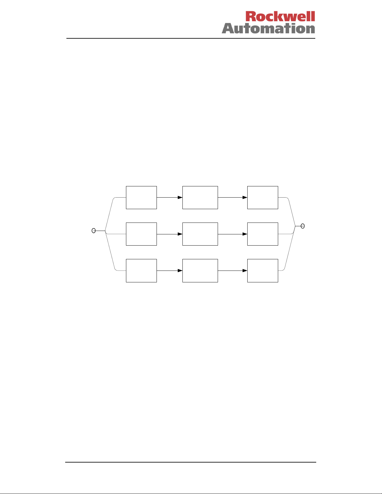
Consider a simple triplicated system, as shown in Figure 1. The input and output
devices are assumed to be simply wired to the input and output channels to provide
the requisite distribution and voting. We have assumed that the output vote is a simple
majority vote for this purpose. Note with non-8000 series systems there may be a
need for a common output-voting element.
INPUT
(Ch. A)
1
INPUT
(Ch. B)
1
INPUT
(Ch. C)
1
PROCESSOR
(Ch. A)
1
PROCESSOR
(Ch. B)
1
PROCESSOR
(Ch. C)
1
Figure 1 - Simple Triplicated System
OUTPUT
(Ch. A)
1
OUTPUT
(Ch. B)
1
OUTPUT
(Ch. C)
1
Doc Number T809 4
Issue 27 – J u n e 2013 Page 5 of 1 0 3
Page 27
SAFETY MANUAL
A failure in any element of each channel, e.g. Ch. A Input, will result in that complete
channel’s failure. If this failure is fail-safe, only 1 of the remaining channels needs to
respond to a demand condition to generate the safe reaction. If a second channel fails
safe then the overall system will fail-safe. This is therefore a 3-2-0 architecture.
Typically diagnostics are used to ensure that the fail-safe state can be assured, the
operation is therefore 2-oo-3D, reverting to 1-oo-2D, reverting to fail-safe.
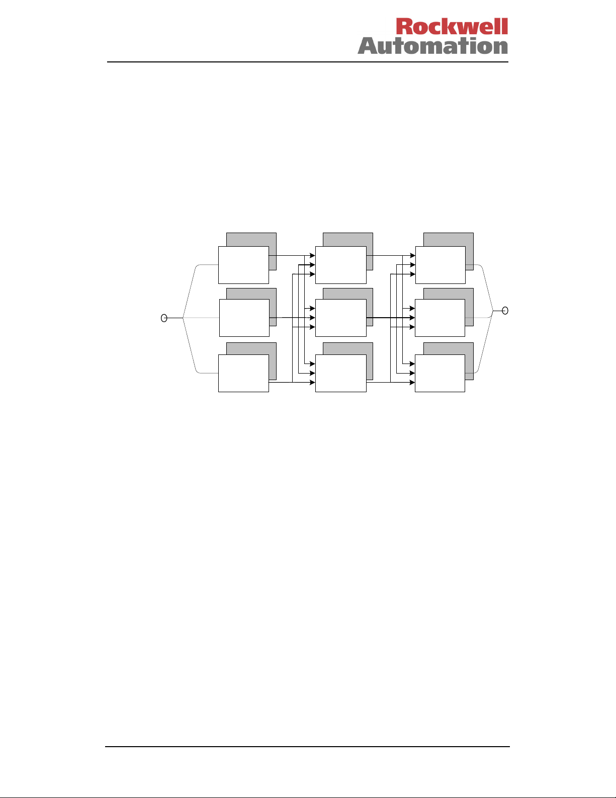
The 8000 series is a TMR system; this means that each stage of the system is
triplicated, with the results from each preceding stage majority voted to provide both
fault tolerance and fault detection. Diagnostics are also used to ensure that covert
failures are detected and result in the correct fail-safe reaction. For example, a fault
within Input Ch. A will be localised to that input, and unlike the standard triplicated
system, will allow Processor Ch. A and Output Ch. A to continue operation, i.e. the
input is now operating 1-oo-2D whilst the remainder of the system continues to operate
2-oo-3.
Diagnostics
INPUT
(Ch. A)
1
Diagnostics
INPUT
(Ch. B)
1
INPUT
(Ch. C)
1
Diagnostics
PROCESSOR
(Ch. A)
1
Diagnostics
PROCESSOR
(Ch. B)
1
DiagnosticsDiagnostics
PROCESSOR
(Ch. C)
1
Diagnostics
OUTPUT
(Ch. A)
1
Diagnostics
OUTPUT
(Ch. B)
1
Diagnostics
OUTPUT
(Ch. C)
1
Figure 2 – TMR Architecture
The 8000 Series utilises this Triple Modular Redundant architecture with diagnostics,
supporting a 2-oo-3D reverting to 1-oo-2D reverting to fail-safe, or 3-2-0 operation.
The 1-oo-2D operation is a transient mode of operation where active and standby
modules are installed; in this case, the degradation is 3-2-3-2-0.
The architecture, and hence degradation modes for low density I/O may be selected as
required, see para. 3.2 in this Manual for further details.
Doc Number T809 4
Issue 27 – J u n e 2013 Page 6 of 1 0 3
Page 28

SAFETY MANUAL
1.4 THE 8000 SERIES OVERVIEW
The TMR system is based on a triplicated microprocessor with internal redundancy of
all critical circuits. The system controls complex and often critical processes in real
time - executing programs that accept external sensor signals, solving logic equations,
performing calculations for continuous process control and generating external control
signals. These user-defined application programs monitor and control real-world
processes in the oil and gas, refining, rail transit, power generation and related
industries across a wide range of control and safety applications. The TMR system is
certified for use in safety-related applications such as fire and gas detection, and
emergency shutdown up to requirements of IEC 61508 SIL 3.
Application programs for the TMR system are written and monitored using the
IEC1131 TOOLSET , a Microsoft® Windows NT™, Windows 2000™, or Windows
XP™, based software suite running on a personal computer.
The TMR architecture provides a flexibility that allows each system to be easily
adapted to the different needs of any installation. This flexibility permits the user to
choose from different levels of I/O fault protection and provides a variety of I/O
interfacing and communications methods, thereby allowing the system to communicate
with other equipment and field devices.
Those elements of the system that are to be used in safety-related operations are
certified to IEC 61508 SIL 3. The remaining elements of the system are certified for
non-interfering operation.
This manual covers the release as specified in the certified module list.
Doc Number T809 4
Issue 27 – J u n e 2013 Page 7 of 1 0 3
Page 29

SAFETY MANUAL
2. SAFETY PRINCIPLES
2.1 INTRODUCTION
This paragraph provides an overview of generic safety principles with emphasis on the
system integration process. These principles are applicable to all safety-related
systems, including, but not limited to, the 8000 series system.
2.2 SAFETY MANAGEMENT
A prerequisite for the achievement of functional safety is the implementation of
procedural measures applicable to the safety lifecycle; these are collectively referred to
as a Safety Management System. The Safety Management System defines the
generic management and technical activities necessary for functional safety. In many
cases, the Safety Management and Quality systems will be integrated within a single
set of procedures. It is highly recommended that the integrator have a quality
management system in accordance with ISO9000.
The safety management system shall include:
• A statement of the policy and strategy to achieving functional safety.
• A Safety Planning Procedure. This shall result in the definition of the safety
lifecycle stages to be applied, the measures and techniques to be applied at
each stage, and responsibilities for completing these activities.
• Definitions of the records to be produced and methods of managing these
records, including change control. The change control procedures shall
include records of modification requests, the impact analysis of proposed
modifications and the approval of modifications. The baseline for change
control shall be defined clearly.
• Configuration items shall be uniquely identified and include version
information, e.g. system and safety requirements, system design
documentation and drawings, application software source code, test plans,
test procedures and results.
• Methods of ensuring that persons are competent to undertake their activities
and fulfil their responsibilities.
Expansion of these requirements is included within the following sub-paragraphs.
Doc Number T809 4
Issue 27 – J u n e 2013 Page 8 of 1 0 3
Page 30

SAFETY MANUAL
2.2.1 Safety Lifecycle
The Safety Lifecycle is designed to structure a system’s production into defined stages
and activities, and should include the following elements:
• Scope definition
• Functional requirements specification
• System safety requirements specification
• System engineering
• Application programming
• System production
• System integration
• System safety validation
• System installation and commissioning
• System operation and maintenance procedures
• System modification
• Decommissioning
The definition of each lifecycle stage shall include its inputs, outputs and verification
activities. It is not necessary to have stages within the lifecycle addressing each of
these elements independently; it is important that all of these stages be covered within
the lifecycle. Specific items that need to be considered for each of these lifecycle
elements are described in the following sub-paragraphs.
2.2.1.1 Scope Definition
The initial step in the system lifecycle should establish the bounds of the safety-related
system and a clear definition of its interfaces with the process and all third party
equipment. This stage should also establish the requirements resulting from the
intended installation environment, including climatic conditions, power sources, etc.
In most cases, the client will provide this information. It is necessary to review this
information and establish a thorough understanding of the intended application, the
bounds of the system to be provided and its intended operating conditions. An
example checklist for the review of the scope definition is given in para. 4.1.1.
2.2.1.2 Functional Requirements
This stage is to establish the complete set of functions to be implemented by the
system. The timing requirements for each of the functions are also to be established.
Where possible, the functions should be allocated to defined modes of operation of the
process.
For each function, it is necessary to identify the process interfaces involved in each of
the functions. Similarly, where the function involves data interchanged with third party
equipment, the data and interface are to be clearly identified. Where non-standard
field devices, communications interfaces or communications protocols are required, it
is important that the detailed requirements for these interfaces be established and
recorded at this stage. In general, the client will provide the functional requirements. It
is, however, necessary to collate these requirements into a document, or document
set, including any clarification of the functional requirements. In cases where the client
provides the functional requirements in an ambiguous form it will be necessary to
clarify, document and establish agreement on the requirements with the client. It is
recommended that logic diagrams be used to represent the required functionality. An
example checklist for the review of the functional requirements is given in para. 4.1.2.
Doc Number T809 4
Issue 27 – J u n e 2013 Page 9 of 1 0 3
Page 31

SAFETY MANUAL
2.2.1.3 Safety Requirements
The functional requirements shall be analysed to determine their safety relevance.
Where necessary, additional requirements shall be established to ensure that the plant
will fail-safe in the case of failures within the plant, the safety-related system, external
equipment and communications or the safety-related system’s environment.
For each safety-related function the required safety requirements class and safetyrelated timing requirements shall be defined. The client should supply this information.
Where this information is not supplied it shall be established and agreed with the client
as part of this phase. It is highly recommended that the client approve the resulting
safety requirements. An example checklist for the review of the safety requirements is
given in para. 4.1.3.
2.2.1.4 Systems Engineering
This stage realises the safety-related system design. It is recommended that the
engineering comprise two stages, the first defining the overall system architecture, and
the second detailing the engineering of the architectural blocks.
The overall system architecture shall identify the individual systems. The architecture
for these systems and for their sub-systems shall include any diverse or other
technology elements.
The architectural definition shall include the required safety requirements class for
each architectural element and identify the safety functions allocated to that element.
Additional safety functions resulting from the selected system architecture shall be
defined at this stage. The detailed engineering shall refine the architectural elements
and culminate in detailed information for system build. The detailed design shall be in
a form that is readable, readily understood and allows for simple inspection/review.
Tools used within the system engineering process are to be carefully selected, with
due consideration of the potential of introduction of error and the required safety
requirements class. Where there remains the possibility of error, procedural methods
of detecting such errors shall be included within the process.
2.2.1.4.1 Safety Requirements Allocations
The overall system architecture shall define the individual system. The architecture for
these systems, and for their sub-systems, shall include any diverse or other technology
elements. The architectural definition shall also define the required safety
requirements class for each architectural element and identify the safety functions
allocated to that element. Additional safety functions resulting from the selected
system architecture will be defined at this stage.
The detailed engineering shall refine the architectural elements and culminate in
detailed information for system build. The detailed design shall be in a form that is
readable, readily understood and allows for simple inspection/review.
Tools used within the system engineering process are to be carefully selected, with
due consideration of the potential for the possibility of introduction of error and the
required safety requirements class. Where there remains the possibility of error,
procedural methods of detecting such errors shall be included within the process.
Doc Number T809 4
Issue 27 – J u n e 2013 Page 10 of 1 0 3
Page 32

SAFETY MANUAL
2.2.1.5 Application Programming
An overall Application Program software architecture is to be defined. This
architecture will identify the software blocks and their allotted functions.
The application architectural design shall be used to define the additional requirements
resulting from the system hardware design. Specifically, methods for addressing
system specific testing, diagnostics and fault reporting are to be included.
It is highly recommended that simulation testing be performed on each software block.
This simulation testing should be used to show that each block performs its intended
functions and does not perform unintended functions.
It is also highly recommended that software integration testing be performed within the
simulation environment before hardware-software integration. The software
integration testing will show that all software blocks interact correctly to perform their
intended functions and do not perform unintended functions.
The development of the application software shall follow a structured development
cycle; the minimum requirements of which are:
• Architectural definition. The application program shall be divided into
largely self-contained ‘blocks’ to simplify the implementation and testing.
Safety and non-safety functions should be separated as far as possible at
this stage.
• Detailed design and coding. This stage details the design, and implements
each of the blocks identified during the architectural definition.
• Testing. This stage verifies the operation of the application; it is
recommended that the application blocks first be tested individually and then
integrated and tested as a whole. This should be initially undertaken within
the simulation environment.
The resultant Application Programs shall be integrated with the system hardware and
integration testing performed.
2.2.1.6 System Production
The system production stage implements the detailed system design. The production
techniques, tools and equipment used within the production testing of the system shall
be commensurate with the required safety requirements class.
2.2.1.7 System Integration
This stage shall integrate the Application Programs with the target systems. Where
multiple systems are used to meet the overall requirement, it is suggested that each
system undergoes individual application program and target system integration before
overall system integration is performed. To meet the requirements of the intended
safety requirements class, the system integration shall ensure the compatibility of the
software and hardware.
Doc Number T809 4
Issue 27 – J u n e 2013 Page 11 of 1 0 3
Page 33

SAFETY MANUAL
2.2.1.8 Installation and Commissioning
The system installation stage shall define the steps to be undertaken to ensure that the
system is installed correctly and commissioned on the plant. These steps shall include
the physical and electrical installation of the system.
The installation environment is a potential source of common cause failure. Therefore,
it is vital that compatibility of the equipment is established. The `environment` for
these purposes includes the climatic, hazardous area, power, earthing and EMC
conditions. In many cases, there may not be a single installation environment.
Elements of the system may be installed in differing location, i.e. central control room,
equipment rooms and field installations. In these cases, it is important to establish the
equipment and environment compatibility for each site.
The first step in the installation sequence is typically the physical installation of the
system. Where the system comprises a number of physically separate units, it is
important that the sequence of installation be established. This may include the
installation of termination facilities before the remaining elements of the system. In
these cases, it is important to establish that independent installation and testing
facilities are available.
Each installation shall be designed to ensure that the control equipment is not
operated in environments that are beyond its design tolerances. Therefore,
consideration should be given to the proper control of temperature, humidity, vibration
and shock, as well as adequate shielding and earthing to ensure that exposure to
electromagnetic interference and electrostatic discharge sources are minimised.
The commissioning stage is to establish the system hook-up and verify its correct ‘endto-end’ functionality, including the connection between the TMR system and the
required sensors and final elements. It is likely that groups of functions are
commissioned rather than the system as a whole, i.e. accommodation area functions
before production functions. In these cases, it is important to establish the
commissioning sequence and the measures to be taken to ensure safe operation
during periods of partial commissioning. These measures shall be system specific and
shall be defined clearly before commissioning. It is important to establish that any
temporary measures implemented for test purposes or to allow partial commissioning
are removed before the system, as a whole, becomes live.
Records shall be maintained throughout the commissioning process. These records
shall include records of the tests completed, problem reports and resolution of these
problems.
Doc Number T809 4
Issue 27 – J u n e 2013 Page 12 of 1 0 3
Page 34

SAFETY MANUAL
2.2.1.9 Safety System Validation
Safety system validation shall test the integrated system to ensure compliance with the
requirements specification at the intended safety requirements class. The validation
activities should include those necessary to establish that the required safety functions
have been implemented under normal start-up, shutdown and abnormal fault modes.
The validation shall ensure that each functional safety requirement has been
implemented at the required safety integrity level, and that the realisation of the
function achieves its performance criteria, specifically that the process safety time
requirements have been met. The validation shall also consider the potential external
common cause failures, i.e. power sources, environmental conditions, and ensure that
the system will provide fail-safe operation in the event of conditions exceeding its
capabilities.
2.2.1.10 Operation and Maintenance Plan
This Operation and Maintenance requirement ensures that functional safety continues
beyond the design, production, installation and commissioning of the system. The inservice operation and maintenance is normally beyond the system integrator
responsibility. However, guidance and procedures shall be provided to ensure that the
persons or organisations responsible for Operation and Maintenance maintain the
intended safety levels.
The Operating and Maintenance Plan shall include the following:
• Although the TMR product requires no specific power-up and power-down
requirements, it is possible that the project specific implementation will
dictate specific action sequences. These sequences shall be clearly defined,
ensuring that the sequences cannot result in periods of the system’s inability
to respond safely whilst a hazard may be present.
• The Maintenance Plan shall detail the procedures to be adopted when
re-calibrating sensors, actuators and I/O modules. The recommended
calibration periods shall also be included.
• The Maintenance Plan shall include the procedure to be adopted for testing
the system, and the maximum intervals between manual testing.
• Sensor and actuator maintenance will require the application of overrides in
certain circumstances. Where these are required, they shall be implemented
in accordance with the guidance provided within this document.
2.2.1.10.1 Planned Maintenance
In most system configurations there will be some elements that are not tested by the
system’s internal test facilities. These may be the final passive elements in some I/O
modules types, the sensors and actuators themselves and the field wiring. A regime of
Planned Maintenance testing shall be adopted to ensure that faults do not accumulate
within those elements that could ultimately lead to the system’s inability to perform its
required safety functions. The maximum interval between these tests shall be defined
during the system design, i.e. before installation. It is highly recommended that the
test interval be less than 12 months.
Doc Number T809 4
Issue 27 – J u n e 2013 Page 13 of 1 0 3
Page 35

SAFETY MANUAL
2.2.1.10.2 Field Device Maintenance
During the lifetime of the system, it will be necessary to undertake a number of field
maintenance activities that will include re-calibration, testing and replacement of
devices. Facilities should be included within the system design to allow these
maintenance activities to be undertaken. Similarly, the operating and maintenance
plan needs to include these maintenance activities, and their effect on the system
operation and design. In general, adequate provision for these measures will be
defined by the client, and provided the facilities, i.e. maintenance overrides, are
implemented within the requirements specified within this document. No further safety
requirements will be required.
It is highly recommended that the I/O forcing capability NOT be used to support field
device maintenance; this facility is provided to support application testing only. Should
this facility be used, the requirements defined in para. 3.8 shall be applied.
2.2.1.10.3 Module Fault Handling
When properly configured and installed, the TMR system is designed to operate
continuously and correctly even if one of its modules has a fault. When a module does
have a fault it should be replaced promptly to ensure that faults do not accumulate,
thereby causing multiple failure conditions that could cause a plant shutdown. All
modules permit live removal and replacement, and modules within a fault-tolerant
configuration can be removed with no further action. Modules that do not have a
partner slot or smart slot configured and have a fail-safe configuration will require the
application of override or bypass signals for the period of the module removal to
ensure that unwanted safety responses are not generated inadvertently.
On-site repair of modules is not supported; all failed modules should be returned for
repair and/or fault diagnosis. The return procedure for modules should include
procedures to identify the nature and circumstances of the failure and the system
response. Records of module failures and repair actions shall be maintained.
2.2.1.10.4 Monitoring
In order to establish that the safety objectives have been met through the lifetime of
the system it is important to maintain records of the faults, failures and anomalies.
This requires the maintenance of records by both the end-user and the system
integrator. The records maintained by the end-user are outside the scope of this
document; however, it is highly recommended that the following information be
included:
• Description of the fault, failure or anomaly
• Details of the equipment involved, including module types and serial
numbers where appropriate
• When the fault was experienced and any circumstances leading to its
occurrence
• Any temporary measures implemented to correct or work around the problem
• Description of the resolution of the problem and reference to remedial action
plans and impact analysis
Each system integrator should define the field returns, repair and defect handling
procedure. The information requirements placed on the end user because of this
procedure should be clearly documented and provided to the end user. The defect
handling procedure shall include:
• Method of detecting product related defects and the reporting of these to the
original designers.
Doc Number T809 4
Issue 27 – J u n e 2013 Page 14 of 1 0 3
Page 36

SAFETY MANUAL
• Methods for detecting systematic failure that may affect other elements of the
system or other systems, and links to the satisfactory resolution of the
issues.
• Procedures for tracking all reported anomalies, their work around and/or
resultant corrective action where applicable.
2.2.1.11 System Modification
Design changes will inevitably occur during the system lifecycle; to ensure that the
system safety is maintained, such changes shall be carefully managed. Procedures
defining the measures to be adopted when updating the plant or system shall be
documented. These procedures shall be the responsibility of the end-user. The
system integrator shall provide sufficient guidance to ensure that these procedures
maintain the required level of functional safety. Special consideration shall be given to
the procedures to be adopted in case of product level updates and enhancement, i.e.
module and firmware updates. Updates to the system shall include considerations of
the requirements for application changes and firmware changes. These procedural
measures shall include:
• Requirement to undertake impact analysis of any such changes
• The measures to be implemented during the modification to the system and
its programming. These measures shall be in-line with the requirements
within this document. Specifically, the requirements defined in sections 2.2
to 2.2.1.8 shall be applied, as well as the additional requirements defined in
this paragraph (2.2.1.11).
• The definition of these procedures shall include the review and authorisation
process to be adopted for system changes.
2.2.1.11.1 Baselines
Baselines shall be declared beyond which any change shall follow the formal change
management procedure. The point within the lifecycle at which these baselines are
declared depends on the detail of the processes involved, the complexity of the
system, how amenable to change these processes are, and the required safety
requirements class. It is recommended that the baseline for formal change process is
the completion of each step in the lifecycle. However, as a minimum the baseline shall
be declared before the presence of the potential hazards, i.e. before start-up.
2.2.1.11.2 Modification Records
Records of each requested or required change shall be maintained. The change
management procedure shall include the consideration of the impact of each of the
required/requested changes before authorising the implementation of the change. The
implementation of the change should repeat those elements of the lifecycle
appropriate to the change. The test of the resultant changes should include nonregression testing in addition to test of the change itself.
Doc Number T809 4
Issue 27 – J u n e 2013 Page 15 of 1 0 3
Page 37

SAFETY MANUAL
2.2.1.12 Decommissioning
The procedure for decommissioning the system shall be defined. This procedure is to
include any specific requirements for the safe decommissioning of the system and,
where applicable, the safe disposal or return of materials.
As with commissioning, it is likely that the decommissioning be performed in a phased
manner. The decommissioning procedure shall ensure that a plan be developed that
maintains the functional safety whilst the corresponding hazards are present.
Similarly, the installation environment of the control equipment shall be maintained
within its operating envelope whilst it is required to function.
• The decommissioning plan shall identify the sequence that the hazards are
to be removed.
• Methods shall be defined to ensure that the interaction between safety
functions can be removed without initiating safety responses and still
maintain safety functionality for the remaining potential hazards. This shall
include the interaction between systems.
• The decommissioning procedure shall define which modules/materials are to
be returned for safe disposal following decommissioning.
2.3 FUNCTIONAL SAFETY ASSESSMENT
The functional safety assessment process shall confirm the effectiveness of the
achievement of functional safety for the system. The functional safety assessment, in
this context, is limited to the safety-related system and will ensure that the system is
designed, constructed and installed in accordance with the safety requirements.
Each required safety function and its required safety properties shall be considered.
The effects of faults and errors within the system and application programs, failure
external to the system and procedural deficiencies in these safety functions are to be
considered.
The assessments are to be undertaken by an audit team that shall include personnel
outside of the project. At least one functional safety assessment shall be performed
before the presence of the potential hazards, i.e. before start-up.
Doc Number T809 4
Issue 27 – J u n e 2013 Page 16 of 1 0 3
Page 38

SAFETY MANUAL
2.3.1 Competency
The achievement of functional safety requires the implementation of the safety
lifecycle and ensuring that persons who are responsible for any safety lifecycle
activities are competent to discharge those responsibilities.
All persons involved in any safety lifecycle activity, including management activities,
shall have the appropriate training, technical knowledge, experience and qualifications
relevant to the specific duties they have to perform. The suitability of persons for their
designated safety lifecycle activities shall be based on the specific competency factors
relevant to the particular application and shall be recorded.
The following competence factors should be addressed when assessing and justifying
the competence of persons to carry out their duties:
• Engineering experience appropriate to the application area.
• Engineering experience appropriate to the technology.
• Safety engineering experience appropriate to the technology.
• Knowledge of the legal and safety regulatory framework.
• The consequences of failure of the safety-related system.
• The safety requirements class of the safety-related systems.
• The novelty of the design, design procedures or application.
• Previous experience and its relevance to the specific duties to be performed
and the technology being employed.
In all of the above, the higher risk will require increased rigour with the specification
and assessment of the competence.
Doc Number T809 4
Issue 27 – J u n e 2013 Page 17 of 1 0 3
Page 39

SAFETY MANUAL
3. SYSTEM RECOMMENDATIONS
3.1 INTRODUCTION
This paragraph expands on and applies the safety principles described earlier in this
Manual. Many of the recommendations within this paragraph are equally applicable to
other safety-related systems. However, the details of the recommendations or
requirements are specific to the TMR system.
3.2 I/O ARCHITECTURES
The TMR system has very comprehensive internal diagnostics that reveal both covert
and overt failures. The hardware implementation of many of the fault tolerance and
fault detection mechanisms provides for rapid fault detection for most system
elements. Self-test facilities used to diagnose faults within the remainder of the
system are defined to provide optimum safety availability. These self-test facilities may
require short periods of off-line operation or introduce conditions, i.e. alarm or fault test
conditions, which effectively result in the point being off-line within that redundant
channel. Within TMR configurations, this period of off-line operation only affects the
system’s ability to response under multiple fault conditions.
The TMR Processors, TMR Interfaces, Expander Interfaces and Expander Processors
are all naturally redundant and have been designed to withstand multiple faults and
support a fixed on-line repair configuration in adjacent slots and therefore require little
further consideration. The input and output modules support a number of architecture
options, the effects of the chosen architecture should be evaluated against the system
and application specific requirements.
Doc Number T809 4
Issue 27 – J u n e 2013 Page 18 of 1 0 3
Page 40

SAFETY MANUAL
3.2.1 Safety-Related Configurations
TÜV Certified
Configuration
TMR Processor
8110
TMR Processor
8110B (IRIG-B)
Peer to Peer
Software board
definitions Dxpdi16,
Dxpdo16,
Dxpai16,
Dxpao16,
Certified for use over
network or multiple
2oo3
2oo3
a single
communication
networks
Dxpdi128,
Dxpdi128 &
dxpnc40
Peer to Peer
Software board
definitions
Dxpai128 &
Dxpao128
TMR Interface
8160
Communication
Interface
8150 / 8151 / 8151B
Expander Modules,
(XIM / XPM)
8310 / 8311
Fiber TX/RX Unit
8314
Certified for use over
a single
communication
network or multiple
networks
2oo3
Not safety related but
interference free
Not safety related but
interference free
2oo3
Not safety related but
interference free
2oo3
Conditions
Certified as safety-related and can be used for
safety-critical applications in SIL 3 in single module
or active/standby configurations.
Certified as safety-related and can be used for
safety-critical applications in SIL 3 in single module
or active/standby configurations.
IRIG-B functionality is interference free and can not
be used for safety functions
Certified as safety-related and can be used for
safety-critical communication in SIL 3 applications.
Certified as safety-related and can be used for
safety-critical communication in SIL 3 applications
provided two separate Dxpai128 & Dxpao128
board definitions are used for safety values, the
safety values from the two Dxpai128 boards (or
digital trip points from the values) shall have a
1oo2 vote within the receiving application.
Certified as safety-related and can be used for
safety-critical applications in single module or
active/standby configurations.
Certified as non-interfering safety-related and can
be used for safety-critical communication in SIL 3 as
part of the grey channel in single or dual module
configurations.
Certified as non-interfering safety-related and can
be used for safety-critical communication in SIL 3 as
part of the grey channel in single module or
active/standby configurations.
Certified as non-interfering safety-related and can
be used for safety-critical communication in SIL 3.
Table 2 - Central Modules
Doc Number T809 4
Issue 27 – J u n e 2013 Page 19 of 1 0 3
Page 41

SAFETY MANUAL
TÜV Certified
Configuration
Digital Inputs
8403, Triplicated, 24
VDC
8423, Triplicated,
120VDC
Digital Inputs
8402, Dual,
24 VDC
Digital Inputs
8424, Triplicated,
120 VAC
Analog Inputs
8431, Triplicated
8433, Triplicated,
isolated
Analog Inputs
8432, Dual
Internal 2oo3
(2oo3 implemented in
a single module)
Internal 1oo2D
(1oo2 implemented in
a single module)
Internal 2oo3
(2oo3 implemented in
a single module)
Internal 2oo3
(2oo3 implemented in
a single module)
Internal 1oo2D
(1oo2 implemented in
a single module)
Conditions
Normally energized (de-energize to trip): certified
SIL 3.
Normally de-energized (energize to trip): certified
only for applications that fulfil the requirements
under section 3.2.4.
Normally energized (de-energize to trip): certified
SIL 3.
Normally de-energized (energize to trip): certified
only for applications that fulfil the requirements
under section 3.2.4.
Time-limited operation in degraded mode
Normally energized (de-energize to trip): certified
SIL 3.
Normally de-energized (energize to trip): certified
only for applications that fulfil the requirements
under section 3.2.4.
Within the manufactures specified safety accuracy
limits. The safety state of the analogue input has to
be defined to 0 mA/0 V
Certified SIL 3.
Within the manufactures specified safety accuracy
limits. The safety state of the analogue input has to
be defined to 0 mA/0 V
Time-limited operation in degraded mode.
Certified: SIL 3.
Table 3 - Input Modules High Density I/O
TÜV Certified
Configuration
Digital Outputs
8451, Triplicated 24
VDC
8471, Triplicated
120VDC
8461, Triplicated
48VDC
Digital Outputs
8472, Triplicated
120VAC
Analog Outputs
8480 Analog Output
4-20 mA
Internal 2oo3
(2oo3 implemented in
a single module)
Internal 2oo3
(2oo3 implemented in
a single module)
Not safety related but
interference free
Conditions
Normally energized (de-energize to trip): certified
SIL 3.
Normally de-energized (energize to trip): certified
only for applications that fulfil the requirements
under section 3.2.4.
May be used in single module or active/standby
configurations.
Normally energized (de-energize to trip): certified
SIL 3.
Normally de-energized (energize to trip): certified
only for applications that fulfil the requirements
under section 3.2.4.
May be used in single module or active/standby
configurations.
Certified as non-interfering and can be used for nonsafety-critical output devices.
Table 4 - Output Modules High Density I/O
Doc Number T809 4
Issue 27 – J u n e 2013 Page 20 of 1 0 3
Page 42

SAFETY MANUAL
TÜV Certified
Configuration
Speed Monitor
Module
8442, Triplicated,
Pulse Generator
8444, Triplicated,
24VDC
Zone Interface
8448 Triplicated,
24VDC
Valve Monitor
8449, Triplicated,
24VDC
Internal 2oo3
(2oo3 implemented in
a single module)
Not safety related but
interference free
Internal 2oo3
(2oo3 implemented in
a single module)
Internal 2oo3
(2oo3 implemented in
a single module)
Conditions
Inputs:
Within the manufactures specified safety accuracy
limits.
Outputs:
Normally energized (de-energize to trip relays).
Normally open or Normally closed Contacts can be
used
Certified SIL 3.
Certified as non-interfering and can be used for non-
safety-critical devices.
Outputs:
Normally energized (de-energize to trip): certified
SIL 3.
Normally de-energized (energize to trip): certified
only for applications that fulfil the requirements
under section 3.2.4.
May be used in single module or active/standby
configurations.
Inputs:
Normally de-energized (energize to trip): only for
applications that fulfil the requirements under
section 3.2.4, and only for “trip amplifier” (like gas
inputs) or quasi digital inputs (like fire loops).
Normally energized (de-energize to trip): certified
only if the inputs are dynamically transitioned at a
period not greater than the second fault occurrence
time.
Analog measurements: certified only if the input is
dynamically exercised over its full range within a
period shorter than the second fault occurrence
time3.
Non-interfering for non-safety-critical devices
Outputs:
Normally energized (de-energize to trip): certified
SIL 3.
Normally de-energized (energize to trip): certified
only for applications that fulfil the requirements
under section 3.2.4.
Safety critical valve may only be tested towards the
safe position.
May be used in single module or active/standby
configurations.
Inputs:
Certified as non-interfering and can be used for non-
safety-critical devices.
Table 5 - Multi-purpose Modules, High Density I/O
3
The analog input must be exercised over it’s full range (i.e. 0 to 4095) over a period of time related to the
safety accuracy specification of the module and the discrepancy detection time configured for the system.
For typical systems, the discrepancy detection time is 200 seconds.
Doc Number T809 4
Issue 27 – J u n e 2013 Page 21 of 1 0 3
Page 43

SAFETY MANUAL
Conditions
Controller Chassis
8100
Expander Chassis
8300
Power Supply Rack
820X
15Vdc Power Supply Unit
8220, 110 - 220 VAC, Dual
Input
24Vdc Power Supply Unit
8225, 110 - 220 VAC, Dual
Input
Certified as safety related and can be used for safety critical
applications in SIL 3
Certified as safety related and can be used for safety critical
applications in SIL 3
Certified as safety related and can be used for safety critical
applications in SIL 3 together with either of the following power
supply units providing reinforced insulation according to EN60950.
Alternatively, any power supply compliant with IEC 61131-2 may be
used
Providing reinforced insulation according to EN60950
Providing reinforced insulation according to EN60950
Table 6 - Auxiliary Modules
Revisions of modules are subject to change. A list of the released versions is held by
TÜV or can be obtained from Rockwell Automation.
Doc Number T809 4
Issue 27 – J u n e 2013 Page 22 of 1 0 3
Page 44

SAFETY MANUAL
3.2.2 High-Density I/O
The High-Density I/O modules are either inherently triplicated or dual redundant with
comprehensive self-test and diagnosis facilities. The self-tests are co-ordinated to
ensure that a majority can be established even in case of a demand during the
execution of the tests. Discrepancy and deviation monitoring further enhance the
verification and fault detection. The TMR Processor tests internal interfaces to the
controller. The culmination of these measures results in high levels of fault detection
and tolerance, ultimately leading to fail-safe operation in the event of multiple fault
conditions. The maximum fault detection time for each module type is specified within
its associated Product Description. In all cases, even in the presence of a fault during
this period, the system will continue to be able to respond. Under multiple fault
conditions the second fault detection period within the repair time may need to be
considered where the system is used in high or continuous demand safety
applications.
All High Density I/O modules include line-monitoring facilities; it is recommended that
these facilities be enabled for safety-related I/O. For normally de-energised I/O these
facilities shall be enabled, see 3.2.4.
Ch. A
Ch. B
Ch. C
Figure 3 - Single High Density TMR I/O Module Architecture
The system supports single module, where it is acceptable to either stop the system or
allow the signals corresponding to that module to change to their default state, and two
active-standby configurations. The first active-standby configuration is to
accommodate the active and spare modules in adjacent slot positions, the second is
use the SmartSlot configuration where a single module position may be used as the
spare for a number of active modules. All configurations may be used for safetyrelated applications; the choice between the configurations supporting live on-line
repair is dependent on the end-user’s preference and the number of faulty modules to
be repaired simultaneously.
Doc Number T809 4
Issue 27 – J u n e 2013 Page 23 of 1 0 3
Page 45

SAFETY MANUAL
Figure 4 - SmartSlot or Adjacent Slot TMR Module Configuration
Standby Module
Ch. A
Ch. A
Ch. B
Ch. B
Ch. C
Ch. C
Active Module
The High Density I/O modules support the system’s inherent TMR architecture. To
annunciate the failure, diagnostic and status information is available within the
corresponding module information available to the application programmer. Faults will
also result in the generation of the corresponding front panel indication on the I/O
module and the system healthy indicator and status output.
A majority fault condition on an I/O point, i.e. a fault beyond its fault tolerant
capability, results in a fail-safe logical state (logical 0). The input state is forced
to “unknown”, state 0x07 in this condition and the analog level to -2048. The
module fault status and fault codes will be set accordingly, and may be
optionally used for remote diagnosis purposes.
The maximum duration for single-channel operation of High Density Dual I/O
modules depends on the specific process and must be specified individually for
each application. For a specific system configuration this time can be
determined through a quantitative analysis performed by Rockwell Automation
using a TÜV approved modelling technique. If no calculation is available, the
maximum duration for single channel operation is 72 hours for (SIL 3) safetyrelated applications.
When a module is operating in a Dual mode (or degraded to a dual mode) and a
state discrepancy occurs. If no module fault is detected, the state reported to
the application will always be the lower of the two states for a digital module,
and the higher of the two states for an analogue module.
In safety critical applications, the channel discrepancy alarms shall be
monitored and alarmed to the operator.
The I/O modules use the active-standby arrangement to support bumpless on-line
repair. The module architecture allows the faulty module to continue normal service
until a replacement module is available and unlike conventional hot-standby
configurations, allows for a controlled transfer even in the presence of a fault condition.
The standby module may be permanently installed to reduce the repair time to an
absolute minimum.
Doc Number T809 4
Issue 27 – J u n e 2013 Page 24 of 1 0 3
Page 46

SAFETY MANUAL
3.2.3 Analog Input Safety Accuracy
When High Density Analog input modules are used, the system uses the median
value. The deviations between the redundant channels’ measurements are monitored
to determine if they are within the safety accuracy limit, refer to the associated
module’s Product Description for its safety accuracy specification. When a single
channel measurement exceeds the safety accuracy limit then a discrepancy alarm is
set for the input channel. Furthermore, should two or more redundant channel
measurements exceed the safety accuracy limit then the reported channel value is set
to -2048 and the channel line fault status set to True.
In safety critical applications, the line fault status shall be monitored by the
application program and be used to initiate the appropriate safety function when
two or more slice readings for a channel exceed the safety accuracy limit.
Furthermore, the discrepancy alarms should be monitored and alarmed to the
operator.
3.2.4 Energise to Action Configurations
Certain applications may require normally open (energise to action) input and energise
to action outputs.
Normally de-energised configurations shall only be used if:
• the activation of the system is only mitigating an already existing
hazard such as in fire and gas applications SIL 1 to SIL 3, or
• the activation of the system is a hazard itself and the system is used in
a SIL 1 to SIL 3 application for 8000 series modules and compliant
application for 7000 series modules.
Additionally the following restrictions apply:
• At least two independent power sources must be used. These power
sources must provide emergency power for a safe process shutdown
or a time span required by the application.
• Each power source must be provided with power integrity monitoring
with safety critical input read back into the TMR system controller or
implicit power monitoring provided by the I/O modules. Any power
failure shall lead to an alarm.
• Unless provided implicitly in the I/O modules, all safety critical inputs
and outputs must be fitted with external line and load integrity
monitoring and safety critical read back of the line-status signals. Any
line or load failure shall lead to an alarm.
• Only modules specifically identified for the use in restricted normally
de-energized configurations shall be used.
In cases where one or more output is used in energise to trip configuration all specific
requirements above are to be followed for all associated inputs.
If energise to trip safety-related outputs are used, line fault conditions shall be
monitored by the system application and alarmed to plant operations personnel.
Line monitor devices shall be installed as close to the field sensor (or actuator if
required) as is practicable. Line fault status shall be monitored by the system
application and alarmed to plant operations personnel.
Line monitoring may also be used in de-energise to trip safety critical input applications
but is not specifically required.
When isolation barriers are used in safety critical applications, line-monitoring
thresholds shall be configured to detect barrier faults. This ensures that barrier
faults do not inhibit the safety critical function.
Doc Number T809 4
Issue 27 – J u n e 2013 Page 25 of 1 0 3
Page 47

SAFETY MANUAL
3.2.5 EN 60204 Category 0 & 1 Configurations
The system is fully compliant for use with category 0 application (de-energise to trip).
Category 1 configurations require a controlled stop with power available to the machine
actuators to achieve the stop and then removal of power.
The 8000 system has a defined internal fail-safe state as de-energised. This could
result in the defined shutdown delay being shortened in some cases of I/O failure, CPU
failure or loss of power to the system.
3.2.6 NFPA 72 Requirements
The 8000 system is certified to be used in NPFA 72 compliant fire alarm systems.
The systems should be designed and integrated in accordance with NFPA 72. In
particular the following shall be applied.
Unless otherwise permitted, all field loops to sensors and actuators, inter-system
and subsystem signal wiring, and communications links shall be line monitored for
single open & short circuits. The fault condition and the restoration to normal shall
be automatically indicated within 200seconds.
3.2.7 NFPA 85 Requirements
The 8000 system is certified to be used in NFPA 85 compliant systems.
The systems should be integrated in accordance with NFPA 85. In particular the
following shall be applied.
• The operator shall be provided with a dedicated manual switch that shall
independently and directly actuate the safety shutdown trip relay. At least one
identified manual switch shall be located remotely from the boiler where it can be
reached in case of emergency.
• The burner management system shall be provided with independent logic,
independent input/output systems, and independent power supplies and shall be a
functionally and physically separate device from other logic systems, such as the
boiler or HRSG control system.
• Momentary Closing of Fuel Values. Logic sequences or devices intended to cause
a safety shutdown, once initiated, shall cause a burner or master fuel trip, as
applicable, and shall require operator action prior to resuming operation of the
affected burner(s). No logic sequence or device shall be permitted that allows
momentary closing and subsequent inadvertent reopening of the main or ignition
fuel valves.
• Documentation shall be provided to the owner and operator, indicating that all
safety devices and logic meet the requirements of the application.
• System response time (i.e. throughput) shall be sufficiently short to prevent
negative effects on the application.
Doc Number T809 4
Issue 27 – J u n e 2013 Page 26 of 1 0 3
Page 48

SAFETY MANUAL
3.2.8 NFPA 86 Requirements
The 8000 system is certified to be used in NFPA 86 compliant systems.
The systems should be integrated in accordance with NFPA 86. In particular the
following shall be applied.
• The supplier of the application software for the programmable controller shall
provide the end user and the authority having jurisdiction with the documentation
needed to verify that all related safety devices and safety logic are functional
before the programmable controller is placed in operation.
• In the event of a power failure, the programmable controller (hardware and
software) shall not prevent the system from reverting to a safe default condition. A
safe condition shall be maintained upon the restoration of power.
• The control system shall have a separate manual emergency switch, independent
of the programmable controller, that initiates a safe shutdown.
• Any changes to hardware or software shall be documented, approved, and
maintained in a file on the site.
• System operation shall be tested and verified for compliance with this standard
and the original design criteria whenever the programmable controller is replaced,
repaired, or updated.
• Whenever application software that contains safety logic or detection logic is
modified, system operation shall be verified for compliance with this standard and
the original design criteria.
• The NFPA certification is only applicable where the system is applied in
accordance with the safety manual and NFPA86 requirements.
• A programmable controller not listed for combustion safety service shall be
permitted to monitor safety interlocks, or to provide burner control functions,
provided that its use complies with both of the following:
(1) The programmable controller shall not interfere with or prevent the operation of
the safety interlocks.
(2) Only isolated programmable controller contacts (not directly connected to a
power source) shall be permitted to be wired in series with the safety interlocks to
permit burner control functions.
Doc Number T809 4
Issue 27 – J u n e 2013 Page 27 of 1 0 3
Page 49

SAFETY MANUAL
3.2.9 EN54 Requirements
The 8000 system is certified to be used in EN 54 compliant systems.
The systems should be integrated in accordance with EN 54. In particular the following
shall be applied.
• Where an alphanumeric display is used to display indications relating to different functional
conditions these may be displayed at the same time. However for each functional
condition there shall be only one window, in which all of the fields relating to that functional
condition are grouped.
• Unless EN 54 section 7.12 applies, the time taken by scanning, interrogation, or other
processing of signals from fire detectors, in addition to that required to take the fire alarm
decision, shall not delay the indication of the fire alarm condition, or of a new zone in alarm
by more than 10 s.
• The control and indicating equipment shall enter the fire alarm condition within 10 s of the
activation of any manual call point
• The audible indication shall be capable of being silenced by means of a separate manual
control at access level 1 or 2. This control shall only be used for silencing the audible
indication, and may be the same as that used for silencing in the fault warning condition.
• The control and indicating equipment shall be capable of being reset from the fire alarm
condition. This shall only be possible by means of a separate manual control at EN 54
defined access level 2. This control shall be used only for reset and may be the same as
that used for reset from the fault warning condition.
• Unless 7.11 and/or 7.12 apply, the control and indicating equipment shall action all
mandatory outputs within 3 s of the indication of a fire alarm condition
• Unless 7.11 applies, the control and indicating equipment shall action all mandatory outputs
within 10 s of the activation of any manual call point.
• The control and indicating equipment shall enter the fault warning condition within 100 s of
the occurrence of the fault or the reception of a fault signal, or within another time as
specified in this European Standard or in other parts of EN 54.
• Total loss of the power supply (option with requirements)
In the event of the loss of the main power source (as specified in EN 54-4), the
control and indicating equipment may have provision to recognize and indicate the
failure of the standby power source to a point where it may no longer be
possible to fulfil mandatory functions of this European Standard. In this case at
least an audible indication shall be given for a period of at least one hour.
• A system fault shall be audibly indicated. This indication may be capable of being
silenced.
• The cabinet of the control and indicating equipment shall be of robust construction,
consistent with the method of installation recommended in the documentation. It
shall meet at least classification IP30 of IEC 60529:2004.
• All mandatory indications shall be visible at access level 1 without prior manual
intervention (e.g. the need to open a door).
• If the control and indicating equipment is designed to be used with a power supply
(item L of figure 1 of EN 54-1) contained in a separate cabinet, then an interface
shall be provided for at least two transmission paths to the power supply, such that
a short circuit or an interruption in one does not affect the other.
Doc Number T809 4
Issue 27 – J u n e 2013 Page 28 of 1 0 3
Page 50

SAFETY MANUAL
[EN54 section 7.12 Co-incidence detection (option with requirements)
[EN54 section 7.11, Delays to outputs (option with requirements - see also 9.4.2.c) and
annex E)
Following the receipt of a signal from a fire detector, and until one or more
confirmatory signals are received from the same or other points, the CIE may
have provision to inhibit either the indication of the fire alarm condition, or
the operation of outputs to
- fire alarm devices (item C of figure 1 of EN 54-1), and/or;
- fire alarm routing equipment (item E of figure 1 of EN 54-1), and/or;
- fire protection equipment (item G of figure 1 of EN 54-1) .
In these cases at least the following shall apply:
a) it shall be possible to select the feature at access level 3 for individual
zones;
b) the inhibition of one output signal shall not affect the actioning of other
outputs.]
The control and indicating may have provision to delay the actioning of outputs
to fire alarm devices (item C of figure 1 of EN 54-1) and/or to fire alarm routing
equipment (item E of figure 1 of EN 54-1). In these cases at least the following
shall apply:
a) the operation of delays to outputs to C shall be selectable at access
level 3 to apply to
- fire detectors, and/or;
- manual call points, and/or;
- signals from specific zones;
b) the operation of delays to outputs to E shall be selectable at access
level 3, to apply to
- fire detectors, and/or;
- signals from specific zones.
c) the delay times shall be configurable at access level 3, in increments not
exceeding 1 minute, up to a maximum of 10 minutes;
d) it shall be possible to override the delays and immediately action delayed
outputs by means of a manual operation at access level 1 and/or by means
of a signal from a manual call point;
e) the delay to one output signal shall not affect the actioning of other outputs.]
Doc Number T809 4
Issue 27 – J u n e 2013 Page 29 of 1 0 3
Page 51

SAFETY MANUAL
3.3 SENSOR CONFIGURATIONS
It is recommended that safety critical process inputs be measured using redundant
input sensors.
Some applications may require multiple sensors and I/O points per safety
function
In safety critical input applications using a single sensor, it is important that the
sensor failure modes be predictable and well understood, so that there is little
probability of a failed sensor not responding to a critical process condition. In
such a configuration, it is important that the sensor be tested regularly, either by
dynamic process conditions that are verified in the TMR system, or by manual
intervention testing.
The function of a signal shall be considered when allocating the module and channel
within the system. In many cases, redundant sensor and actuator configurations may
be used, or differing sensor and actuator types provide alternate detection and control
possibilities. Plant facilities frequently have related signals, e.g. start, and stop signals,
in these cases it is important to ensure that failures beyond the system’s fault-tolerant
capability do not result in either inability to respond safely or in inadvertent operation.
In some cases, this will require that channels be allocated on the same module, to
ensure that a module failure results in the associated signals failing-safe.
However, in most cases, it will be necessary to separate the signals across modules.
Where non-redundant configurations are employed, it is especially important to ensure
that the fail-safe action is generated in case of failures within the system.
Field loop power should be considered in the allocation of signals to input channels
and modules. For normally energised input configurations, field loop power failure will
lead to the fail-safe reaction. As with the allocation of signals to modules, there may
be related functions, e.g. start and stop signals, where loss of field power should be
considered in the same manner as the signal allocation. Where signals are powered
from separate power groups, it is important that this separation be maintained when
allocating the signals to modules, i.e. that they are not connected to input channels
within the same power group.
Doc Number T809 4
Issue 27 – J u n e 2013 Page 30 of 1 0 3
Page 52

SAFETY MANUAL
3.4 ACTUATOR CONFIGURATIONS
As with sensor configurations it is recommended that redundant actuator
configurations be used for safety-critical applications.
Some applications may require multiple actuators and I/O points per safety
function
In safety-critical applications using a single actuator, it is important that the
actuator failure modes be predictable and well understood, so that there is little
probability of a failed actuator not responding to a critical process condition.
In such a configuration, it is important that the actuator be tested regularly, either by
dynamic process conditions that are verified in the TMR system, or by manual
intervention testing.
The function of a signal shall be considered when allocating the module and channel
within the system. In many cases, redundant actuator configurations may be used, or
differing actuator types provide alternate control and mitigation possibilities. Plant
facilities frequently have related signals; in these cases it is important to ensure that
failures beyond the system’s fault-tolerant capability do not result in either an inability
to respond to safety demands or in inadvertent operation. In some cases, this will
require that channels be allocated on the same module, to ensure that a module failure
results in the associated signals failing-safe. However, in most cases, it will be
necessary to separate the signals across modules. Where non-redundant
configurations are employed, it is especially important to ensure that the fail-safe
action is generated in case of failures within the system.
Field loop power should be considered in the allocation of signals to output channels
and modules. For normally energised configurations, field loop power failure will lead
to the fail-safe reaction. As with the allocation of signals to modules, there may be
related functions where loss of field power should be considered in the same manner
as the signal allocation. Where signals are powered from separate power groups, it is
important that this separation be maintained when allocating the signals to modules,
i.e. that inadvertent coupling between power groups, and particularly return paths, are
not generated.
3.5 PFD CALCULATIONS
Systems that are configured to meet the needs of IEC 61508 will require the PFD for
the safety instrumented functions to be calculated.
For information regarding the calculation for the 8000 system and PFD numbers
allocated for the 8000 system pleased refer to the TUV approved PFD calculation
document listed in the approved version list.
Doc Number T809 4
Issue 27 – J u n e 2013 Page 31 of 1 0 3
Page 53

SAFETY MANUAL
3.6 PROCESSOR CONFIGURATION
3.6.1 Timing
The TMR Processor supports a limited set of configuration options; the system will
verify many of the configuration options, for example module locations against actual
module types. The configuration options include the maximum application program
scan time and sleep period between application program scans. It is important to
ensure that the overall application program scan period (scan and sleep
periods) be set according to the PSTE.
3.6.1.1 ISAGRAF_CONFIG Section
Sleep Period (ISA_SLEEP_PERIOD)
This parameter defines the period that the application program should “sleep” between
program scans. This parameter works in conjunction with the allowed scan time
defined within the IEC1131 TOOLSET. The default value for this parameter is zero.
This value may be increased to allow higher levels of processing resource to be
allocated to other tasks, e.g. external communications. Increasing this parameter will
increase the overall scan time. If this parameter is increased, it is important to
ensure that this overall scan time does not result in a response time exceeding
that dictated by PSTE.
The sleep period or the allowed scan time, set in the IEC1131 TOOLSET, should be
adjusted to free up processing resource for other activities. If the sleep period is set to
zero and the application execution to “fast as possible” the system will switch between
the necessary activities as required. Allowing a “free” amount of resource reduces the
switching, improves overall efficiency for the specific application and results in greater
scan period consistency under a range of conditions, rather than a faster scan period,
but variable depending on load.
Maximum Scan Period (MAX_SCAN_TIME)
This parameter defines the maximum application scan time. The default setting is
1000ms. If the defined time is exceeded the system will automatically and immediately
initiate its overall fail-safe response. This value should be set to ensure that the
overall scan time does not exceed the period dictated by PSTE.
3.6.1.2 Composite Scan Time Estimation for the Trusted TMR System
The composite scan time for a Trusted system represents the time required to read
the input data, solve the application logic, and write the output data. This sequence is
repeated cyclically for as long as the Trusted system is executing an application. For
details of the scan time see the scan time calculation section of the TMR Processor
PD for the 8110 & 8110B module.
Doc Number T809 4
Issue 27 – J u n e 2013 Page 32 of 1 0 3
Page 54

SAFETY MANUAL
3.6.2 Diagnostic Access
The TMR Processor supports comprehensive diagnostic facilities. Some of these
facilities have the capability of modifying the system’s operation and are therefore
password protected, to provide access protection in addition to that afforded by
physical access to the system.
The password is defined in the Security section of the system.ini file. The password is
encoded and is not readily decodable from the system.ini text file.
A default password is implemented automatically, however it is recommended
that a specific password be defined within the system.ini file. It is important that
this password be made available only to personnel requiring access to the
additional diagnostic capabilities (typically only Rockwell Automation
personnel). If this password is lost, there is no capability of accessing these functions
without reconfiguring the system.
3.6.3 Configuration File Verification
The system.ini file defines a number of fundamental safety configuration options. It is
important to ensure that the correct file is downloaded to the system and that this file
represents the correct configuration.
1. The system.ini file may be created using either the configuration tool or
a text editor.
2. Once complete, this file should be downloaded to the system.
3. The system.ini file shall then be uploaded from the system and checked
that it contains the required configuration options. This ensures that no
faults have been introduced by the configuration tool, the PC itself, or
the down/upload process.
4. Following this check the checksum of the file (uploaded with the file)
should be recorded, and used to verify that the file has not changed.
3.7 HIGH DENSITY I/O MODULE CONFIGURATION
3.7.1 Module Characteristics
The High Density I/O range has facilities to allow several of its operating parameters to
be adjusted; examples of these include threshold settings, indicator operation, update
rates, etc. The configuration settings available for each module type is defined in its
corresponding Product Description (PD). In many applications, the parameter’s default
values will provide the required operation.
These parameters may be adjusted within the system.ini file, which shall be reviewed
in a similar manner as other system configuration and programming.
Once the configuration settings for a module have been determined, the checksum for
the configuration data may optionally be calculated and entered into the system.ini file
with the appropriate command. This provides further protection against configuration
setting changes if desired. The checksum can be uploaded from the module, once the
settings have been verified for completeness.
Doc Number T809 4
Issue 27 – J u n e 2013 Page 33 of 1 0 3
Page 55

SAFETY MANUAL
3.7.1.1 SYSTEM Section Configuration
The High Density I/O SYSTEM section within the system.ini file allows the internal bus
activity, system watchdog and power failure signal and bypass timeouts to be adjusted.
These may be adjusted for test and development purposes.
Internal Bus Activity (IMBTO)
The default setting (500ms) for the internal bus activity timeout is appropriate for most
applications. This timeout may be adjusted to a shorter period; the adjusted period
shall be shorter than the PSTE less the overall system response time. This
setting SHALL NOT be set to zero for operational systems.
System Watchdog Timeout (WDOGTO)
As with the internal bus activity timeout, it is not normally necessary to adjust this
parameter. This value shall not be adjusted for safety-related applications and
shall not be set to zero for operational systems.
Power Fail Timeout (PWRFAILTO)
The power fail signal timeout shall only be set to zero if the output module is
required to change to its configured fail-safe state, rather than off/de-energised
in the case of loss of communications with, or removal of the TMR Processor.
Bypass Timeout (BYPASSTO)
The Bypass Timeout period to temporarily bypass the other timeouts defined in the
system section during an Active/Standby changeover. Only in exceptional cases will it
be necessary to adjust this setting. This setting shall not be adjusted for safety
related systems and shall not be set to zero for operational systems.
3.7.1.2 FORCE Section
This section allows the reported channel state to be forced directly on the associated
input or output module. This feature is for testing by Rockwell Automation or an
approved systems integrator only, and SHALL NOT to be used in an operational
system.
3.7.1.3 SHUTDOWN Section
This section allows the user to configure individual shutdown states for each output
channel. The options include de-energise, energise and hold. Safety related, de-
energise to trip outputs shall either be left to their default shutdown action
configuration (de-energise) or specifically configured to de-energise. Safety
related, energise to trip outputs should be configured for the energise option.
3.7.1.4 FLAGS Section
This section allows the user to configure the input or output type and the form of
monitoring supported for each channel. For line monitored, safety-related outputs
the logical = TRUE setting shall not be used as this disables the line-monitoring
facility.
3.7.1.5 LED Section
This section allows the user to configure the indicators on the front of each High
Density I/O module. LED color and flash attributes can be specified for each possible
channel state (such as line fault conditions or voltage threshold ranges) Safety
related I/O shall not use steady green to indicate abnormal channel conditions.
Doc Number T809 4
Issue 27 – J u n e 2013 Page 34 of 1 0 3
Page 56

SAFETY MANUAL
3.7.1.6 De Energised Short Circuit Detection Section
This section allows the user to enable the de-energised short circuit detection (default
is disabled). Safety related I/O that is normally De-Energised shall use short
circuit monitoring (see section 3.2.4).
3.7.2 Module Replacement Configuration
The system supports 3 forms of High Density I/O module replacement:
a. Hot-swap pair (companion slot)
b. SmartSlot
c. Live insertion and removal
In the hot-swap pair, 2 adjacent module positions are coupled to provide and active
and standby module pair. If it intended that the system be able to start-up (including
application stop and re-start), on the primary module position, there is no requirement
to define the secondary module position.
If it is intended to allow the system to start with only the secondary module
position occupied, it is important that the module positions be included within
the system.ini file. For Companion Slot modules, enter a module in the primary
slot. Tick ‘Simulate’ and enter the partner chassis and slot location. Do NOT
enter a module in the partner slot.
For SmartSlot pair operation, it is not possible to start-up using the “spare” module
position. The spare module position need not be in the same chassis as the primary
module position.
If it is intended to perform live insertion and removal without transfer to a standby
module no specific configuration is required. If it is intended to start-up a system
without the primary module installed in either a SmartSlot or single module live
insertion and removal configuration, the “simulate” configuration option should be set.
The simulate option will allow the system to start with these modules omitted, the
corresponding states and values being set to their fail-safe conditions.
1. A consistent module replacement philosophy should be used within any
single system. Where mixed philosophies are used, there shall be clear
indication of the repair approach applicable to each module or group of
modules.
2. In hot-swap and SmartSlot configurations, the accuracy with both modules
installed shall be within the plant required safety accuracy specification. If
tighter tolerance is required, ensure that each sensor within a redundant
configuration is allocated to independent modules and procedural measures
are implemented to ensure that only a single module within this set of
modules is paired at any instant.
3. If the SmartSlot module replacement is used, the system shall include
provision for testing the SmartSlot linking cable. This cable shall be tested
before use; the testing of this cable shall be included in the Operating and
Maintenance Manual.
4. In hot-swap configurations, a secondary module that does not pair with the
primary module in a reasonable amount of time (less than the second fault
occurrence time) must be removed.
5. In SmartSlot configurations, a secondary module that does not pair with the
primary module in a reasonable amount of time (less than the second fault
occurrence time) when the SmartSlot linking cable is installed must be
removed.
Doc Number T809 4
Issue 27 – J u n e 2013 Page 35 of 1 0 3
Page 57

SAFETY MANUAL
3.8 INPUT AND OUTPUT FORCING
Locking and forcing of individual inputs and outputs from the IEC1131 Workbench are
supported for engineering, installation and commissioning purposes. In-service,
maintenance overrides for safety-related inputs and outputs should be implemented
using the application program. The IEC1131 Workbench initiated locking and forcing
requires:
• The TMR Processor keyswitch to be in the “Maintain“ position to make
changes to the lock or force status of any point
• Access to the Workbench lock & write commands, which are multi-level
password protected.
• A list of the currently locked points are read back from the TMR system and
made available within the IEC1131 Workbench
The TMR Processor inhibit LED will indicate when one or more I/O points are locked.
The application program can determine how many points are currently locked by used
the information available from the TMR Processor complex equipment; it is highly
recommended that this be used to control additional status display and/or for logging
purposes.
All input and output locks (and forces) can be removed using either a single
function from the IEC1131 Workbench or from an edge triggered signal to the
TMR Processor board within the application program. If locking is used, a
safety-related input connected to an operator accessible switch shall be
implemented to initiate the removal of the lock and force conditions.
It is important that the effects of forcing input and output points on the process and
their safety impact are understood by any person using these facilities.
The system will allow the forced conditions to be maintained during normal operation.
When returning to normal operation it is recommended that all locked and
forced points be returned to normal operation. It is the plant operators’
responsibility to ensure that if forced conditions are present that they do not jeopardise
the functional safety.
Doc Number T809 4
Issue 27 – J u n e 2013 Page 36 of 1 0 3
Page 58

SAFETY MANUAL
3.9 MAINTENANCE OVERRIDES
Maintenance Overrides set inputs or outputs to a defined state that can be different
from the real state during safety operation. It is used during maintenance, usually to
override input or output conditions in order to perform a periodic test, calibration, or
repair of a module, sensor or actuator.
To correctly implement a maintenance override scheme within the TMR Controller the
override, or ‘bypass’ logic shall be programmed within the Application Program, with a
separate set of safety-related input points or variables enabling the bypass logic.
In order to accommodate maintenance overrides safely, TÜV has documented a
set of principles that shall be followed. These principles are published in the
document "Maintenance Override" by TÜV Süddeutschland / TÜV Product
Service GmbH and TÜV Rheinland.
There are two basic methods now used to check safety-related peripherals connected
to the TMR system:
1. Special switches connected to conventional system inputs. These inputs are
used to deactivate sensors and actuators during maintenance. The
maintenance condition is handled as part of the system’s application program.
2. Sensors and actuators are electrically switched off during maintenance and are
checked manually.
In some installations, the maintenance console may be integrated with the operator
display, or maintenance may be covered by other strategies. In such installations, the
guidance given in para. 3.11.5 is to be followed. A checklist for the application of
overrides is given in para. 4.2.3.
Doc Number T809 4
Issue 27 – J u n e 2013 Page 37 of 1 0 3
Page 59

SAFETY MANUAL
3.10 PEER COMMUNICATIONS CONFIGURATION
Peer Communications allows safety-relevant data to pass between numbers of 8000
series TMR systems. When using this mechanism, as with any other, it is important to
ensure that the overall system will respond within the required PSTE. This requirement
applies to normal operation and in the presence of faults.
For safety-related applications, it is recommended that the Peer-to-Peer
Communications use redundant networks. It should be noted that high network
bandwidth usage by non safety system equipment may cause data timeouts and
hence spurious trips, therefore separate networks for the safety data should be
considered.
The Peer-to-Peer Input boards include the configuration of a refresh timeout. This
timeout defines the maximum interval between the receipts of valid, updated data from
an associated (source) system. This timeout period shall be set that if the fault
tolerant capabilities of the Peer-to-Peer Network, (i.e. lack of fresh data is
detected) the system can still respond within the required PSTE. The network
propagation time must be included in the timeout period calculations, and
should be re-verified after each change to the network configuration.
The freshness of the received data is available to the application programmer as part
of the Peer-to-Peer Input board input information. This status is set to ‘TRUE’ or ‘1’
whilst updated data is received within the refresh timeout. If a timeout occurs, this
status bit is set to ‘0’. The data received from the corresponding source system will be
held in its previous state or value in the case of a timeout or go the defined fail safe
state depending on the configuration. If hold last state is selected it is important
that the application programmer include handling of this condition, including
latching of the failure as necessary. For example, the loss of the Peer-to-Peer
Communications link may require a specific safety reaction, or may require that the
corresponding data be set to a specific states or value.
The Peer-to-Peer Output board includes a refresh period. This value defines the
interval between transmissions of the corresponding data if no state or value changes
are received from the local application program. This value shall be set to a period
shorter than that of the input board, unless changes occur constantly, otherwise the
corresponding input boards will timeout.
The Peer-to-Peer master configuration includes transmit timeout values for that
network. The Peer-to-Peer master and slave configurations include response timeout
values. These values are used to determine the link status. This link status
information may be used in addition to the freshness status to allow the source
system, or Peer-to-Peer Communications master to report link status or to act in the
event of link failure.
Release 3.5 and later, Peer to Peer transfers 32 bit values between nodes. The 32 bit
values can be 32 bit unsigned, 32 bit signed or 32 bit floating point depending on the
variable connected to the output board. The variable type used for a particular variable
must match at both the input and output board. A single input and output board pair
can use different data types on different channels provided they match on both the
input and output boards.
3.11 APPLICATION PROGRAM DEVELOPMENT
The IEC1131 Workbench may be connected either directly to the serial
communications ports local to the TMR Processor or via an Ethernet network. Where
Ethernet is used, the network shall not be used to connect equipment not
associated with the TMR system. PCs connected to this network shall not
provide a route to access the TMR system from other networks, i.e. if they
Doc Number T809 4
Issue 27 – J u n e 2013 Page 38 of 1 0 3
Page 60

SAFETY MANUAL
support multiple Ethernets, routing to the dedicated TMR system network shall
be specifically disabled.
Doc Number T809 4
Issue 27 – J u n e 2013 Page 39 of 1 0 3
Page 61

SAFETY MANUAL
3.11.1 IEC1131 Workbench Configuration
The IEC1131 workbench supports 16 levels of password access, level 0 being the
highest access level. Each workbench function (for example, viewing, editing,
compiling, downloading) may be identified for use only by users with an access level
above a certain level.
User access passwords shall be implemented, the recommended access levels
are:
0 – Engineering supervisor
2 – Engineer/Application Programmer
4 – Maintenance Engineer
8 – General User
With the functions allocated as shown in Table 7.
Function Min.
access
level
Global Protection 8 Debug application 8
Overwrite with archive 2 Simulate application 8
Backup on archive 8 Download/stop/start application 4
Project Description 4 Update application 4
History of modifications 8 Communications parameters 8
I/O Connection 2 Set cycle time 2
Global Variables 2 Set execution mode 2
Global & Common Defined Words 2 Change variable state 4
Create New 2 Lock/Unlock variable 4
Move program in hierarchy 2 Control SFC 4
Verify 8 Control Timer 4
Make application code 4 Set IL Breakpoint 4
Touch application 4 Set SFC Breakpoint 4
Conversion tables 2 Create graphics 8
Application runtime parameters 2 List of variables 8
Compiler options 2 List of time diagrams 8
Resource definition 2 Print project document 8
Customise project document 4
Function Min.
access
level
Table 7 - IEC1131 Workbench Recommended Access Levels
Doc Number T809 4
Issue 27 – J u n e 2013 Page 40 of 1 0 3
Page 62

SAFETY MANUAL
3.11.2 Language Selection
The IEC1131 TOOLSET offers many programming tools to develop algorithms to
meet the needs of virtually any real-time control application. The configuration and
programming languages approved for use in SIL 3 safety related application is shown
in Table 8.
Safety
Related
Non-Safety
Table 8 - Safety Related Programming Language
• Safety Related Languages. For those languages that have been classified as
‘safety related’. Commonly used functions have been exhaustively tested and may
be used freely. Those included within the certification testing are shown in para. 5.
Further functions may be used subject to completion of testing commensurate with
the level used for the commonly used functions.
• Non-Safety. The languages that have been classified for non-safety related
application only shall NOT be used within a safety-related system.
IL and ST include program flow control functions; these functions shall be used with
caution to ensure that infinite loop or omitted logic conditions do not result. Where
these constructs are used, it is recommended that full branch and data coverage
tests be performed on these sections of program. It is recommended that only
Boolean conditions be used for these constructs to ensure that a feasible set of
tests can be applied.
Application programmer generated function blocks may be created either on a project
specific or library basis. Where these functions are to be used for safety-related
applications, they shall be subject to exhaustive testing, commensurate with
that used for the commonly used functions (see para. 3.11.3). Once the function
block has been subject to this level of testing it may be used as for commonly used
functions.
There is provision for the TMR system to support multiple programs within a project. A
complete project may be classified as safety or non-safety related. A safety-related
project may use the safety programming languages; non-safety programming
languages cannot be used. A project classified as non-safety may use any of the
programming languages and the full instruction set but shall not be used to implement
safety related functions. A checklist for the selection of programming languages is
given in para. 4.2.2.
Function Block (FB)
Instruction List (IL)
Structured Text (ST)
Ladder Diagrams (LD)
Sequential Function Chart (SFC)
‘C’
Doc Number T809 4
Issue 27 – J u n e 2013 Page 41 of 1 0 3
Page 63

SAFETY MANUAL
3.11.3 Testing of New or Previously Untested Functions
The TMR system Tool set comprises a number of function blocks that can be
combined together to form a project application. The use of these function blocks
in safety certified systems is only permitted once they have been tested for
correct operation. A list of the functions tested prior to the initial certification the TMR
system is provided in section 5 of this Manual.
The new or previously untested function may be:
• a generic function block, which forms part of the Toolset, but has not previously
been subject to the level of testing defined herein, or
• project specific function block, which is written to meet the needs of a particular
feature within an application program, and may comprise a number of generic
function blocks or other program functions
If a previously untested function block is needed, the function block must be tested in
accordance with 3.11.3.1 to 3.11.3.7.
3.11.3.1 Test Method
Each function to be tested shall be placed within an application test harness using the
TMR system Toolset that exercises its capabilities. The implementation of this
harness shall be such that the function block is exercised automatically, so that the
test is repeatable.
As a minimum each test harness shall comprise of all of the following:
• Function Block under test
• Alternative implementation of the function block
• Function generator
• Main and alternative comparison Pass/Fail Flag
• Test results register
Where practical, and with the exception of time, results of the test shall be
automatically recorded and should not require a human to count or record dynamic
data.
3.11.3.2 Alternative Implementation of the Function Block
The test harness shall include an alternative implementation of the function being
tested. This implementation shall be performed using features of the tool set that are
as diverse as possible from the actual function block.
For example an “Or Gate” can be simulated by counting the number of inputs set to a
logical “1” and determining that the count is greater than or equal to 1.
3.11.3.3 Function Generator
The operation of the test harness shall be automatic; a function generator shall be
provided to generate the stimuli for the function under test. This function generator
shall be as simple as possible and shall not contain the function under test.
3.11.3.4 Main and Alternative Comparison Pass/Fail Flag
The results of the alternative implementation shall be compared with the results of the
function under test; discrepancies shall cause a “main and alternative comparison fail
flag” to be set.
Doc Number T809 4
Issue 27 – J u n e 2013 Page 42 of 1 0 3
Page 64

SAFETY MANUAL
3.11.3.5 Test Results Register
Each harness shall include registers that record the functionality of the function block.
This registration should be as comprehensive as possible and should utilise as many
predictable features as possible.
For example, a 2 input logical “Or Gate” stimulated by the two lower bits of a 16-bit
counter will record 32768 logical high states if the counter is allowed to make one
complete up count from 0 to 65536. The results register would count these states and
present a number to the human operator. In this case the results register should also
record that no two consecutive states of the counter caused a logical “1” at the output
of the Gate.
3.11.3.6 Test Coverage
Where possible, all combinations of input shall be simulated.
For certain functions, such as adders and comparators, this is not practical. In these
cases, the test harness shall utilise a significant number of test cases to prove the
functions operation. The use equivalence class, boundary cases and random
numbers shall be used as the preferred method of generating these cases.
Functions containing complex algorithms or with extensive retained state or value
dependence require an extensive number of test cases, and are therefore considered
impractical to achieve a sufficient level of test coverage and shall be used in nonsafety programs only.
3.11.3.7 Recording and Filing of Results
The tests shall utilise formally approved test procedures and the test results shall be
formally recorded. The test harness, details of the test environment and test result
shall be retained.
Any deviation between the results and expected results shall be examined; where this
results from deficiencies in the test harness these shall be corrected and the test
repeated. Should any function fail it shall be:
• Not used within safety related applications, or
• The conditions that result in erroneous operation shall be explicitly recorded
and published. If the function is used, other function(s) shall be added to the
application to specifically detect the conditions leading to erroneous
operation and take a fail-safe action.
To maintain system certification, any test harness used to prove a function block
should be archived as part of the test record so that the tests can be repeated at later
date and if required, reviewed by TÜV.
Doc Number T809 4
Issue 27 – J u n e 2013 Page 43 of 1 0 3
Page 65

SAFETY MANUAL
3.11.4 Application Development
The application program development shall follow a structured approach and follow the
principles defined in para. 2.2.1.5. The stages defined in the following sub-sections
shall additionally be applied for safety related applications.
3.11.4.1 Partitioning the Application
It is impractical and unnecessary to apply the same degree of rigorous development
and testing to all functions within the Application where some of those functions are not
safety related.
The identification of safety functions is, in part, dependent on the specific safety
philosophy. Examples of non-safety may include status indication, data reporting and
sequence of events. It is important to establish that these elements are not safety
related. For example, some safety cases rely on human intervention and therefore the
correct operation of status indication.
The safety related elements shall be implemented within separate programs to
those of non-safety related elements. Where information passes between these
elements, it shall be arranged that the direction of flow is from safety relevant to
non-safety relevant only.
3.11.4.2 Defensive Measures
In defining the Application the programmer must consider the potential sources of error
and apply reasonable defensive programming techniques. Where values are received
from other programs or external communications interfaces, the validity of the values
should be checked where possible. Similarly, values received from input interfaces
should be checked where possible. In many cases, it will also be possible to monitor
permutations of data, inputs and plant operating modes to establish the plausibility of
the information and program measures to ensure safe responses in case of
implausible conditions.
Safety related functions shall be latched when in their tripped state to prevent
intermittent field faults from removing the trip condition. The application
software shall be written to ensure that safety related functions are in their safe
state during system startup.
3.11.4.3 Testable Blocks
Each safety-related software block shall be 100% testable. A 100% testable block is
the application logic that belongs to one safety function. Such functions could be:
• Burner flame supervision including temperature, air/gas pressure monitoring,
etc.
• Burner gas-to-air ration control/supervision
• Parts or whole of the start-up sequence of a batch reactor
The fewer the number of inputs, outputs and signal paths, the fewer the number of
permutations that require testing. However, a single safety function should not be split
into separate blocks; such a division is likely to lead to the introduction of errors during
maintenance activities.
The interaction between the individual software blocks shall be minimised. Where
interaction is necessary, it should be kept as simple as possible, for example a single
shutdown initiation signal.
Doc Number T809 4
Issue 27 – J u n e 2013 Page 44 of 1 0 3
Page 66

SAFETY MANUAL
Each safety function shall be responsible for the control of the corresponding outputs.
Sharing of outputs between functions shall not be permitted.
3.11.4.4 Individual Safety Related Functions
The TMR system IEC1131 TOOLSET allows the definition of up to 250 individual
programs within a single project. This facility should be exploited to enable the
allocation of individual safety related functions to separate programs. Where such
programs contain independent logic paths, these should be investigated to determine if
they are separate safety functions. Where they are separate, it is recommended that
these be further allocated to their own program, subject to conforming to the
recommendation to minimising the coupling between programs.
Cases should be looked for that allows the creation of individual logic paths by
repeating small sections of logic rather than fanning out the resultant signal(s).
3.11.4.5 Minimise Logic Depth
Where possible, the logic depth should be minimised. This helps reduce visual
complexity, simplifies testing, minimises the number of interconnects required and
improves program efficiency.
Where there is nested logic, it shall be possible to establish the correct operation of all
intermediate logic connections.
The use of memory, i.e. latches, components within the safety function shall be
minimised. Similarly, the permutation of conditions that lead to their activation shall be
minimised.
3.11.5 Communications Interaction
The TMR system provides a range of communications options to allow interaction with
external systems. Where this communication is used for reporting (or out-going)
communications, there are no specific safety requirements.
Data received from external equipment that either controls safety-related functions or
affects their operation must be handled with caution. The Application Program shall
handle the received data.
The received data should be such that it is limited to interaction which:
• Initiates safety operations, i.e. initiates shutdown sequences
• Resets signals, with the reset action only possible once the initiating
conditions have been removed
• Initiate timed start-up override signals which are removed automatically
either on expiration of the start period or once the associated signal has
stabilised in the normal operating condition
• Adjust control parameters within defined safe operational limits, i.e. lowering
of trip thresholds.
Where the interaction does not fall within these categories, the affects of incorrect
values and sequences of values shall be considered and measures taken to ensure
that the system will respond safely in the event of erroneous data. Alternatively,
measures may be implemented within the application to ensure the integrity and
validity of the data.
Doc Number T809 4
Issue 27 – J u n e 2013 Page 45 of 1 0 3
Page 67

SAFETY MANUAL
3.11.6 Program Testing
Even with a small number of inputs, it is possible to reach a point where the number of
tests becomes unreasonable. Eliminating impossible or unlikely scenarios should be
used to reduce the number of logic path tests that need to be performed. The
selection of what constitutes a scenario that does not require testing can be performed
only after a suitable hazard analysis.
The scenarios should include possible plant conditions, sequences of plant conditions,
system conditions (including partial power conditions, module removal and fault
conditions).
Where it is not possible to define a representative suite of test cases, all permutations
of input conditions, i.e. all possible states on all possible inputs, shall be exercised.
Where the logic includes memory or timing elements, additional tests shall be defined
to exercise all the possible sequences of input permutations leading to their operation.
All safety-related functions shall be tested and the results of the tests recorded.
The tests shall include the system scan time, fault detection time, fault reaction
time and throughput delay for shutdown logic. The system scan time, including
Peer-to-Peer Communications where appropriate, shall be less than ½ PSTE.
Functional testing of all safety related programs is considered to be 100% if:
• All inputs are exercised through their entire allowable range
• All outputs are exercised through their entire program determined range
• All logic paths are exercised
• All timers have been tested regarding their timing characteristics without
changing timing parameters
• All combinatorial permutations of digital signals, with the exception of 100%
tested function blocks, are tested, including fault states.
• All combinatorial permutations of analogue signals, with the exception of
100% tested function blocks, are tested within the safety accuracy
granularity.
• All timing properties of each safety loop have been verified
3.11.6.1 Cross Reference Checking
While the aim shall be to minimise the coupling and dependencies between individual
programs, there will inevitably be occasions where, for example, a variable is used
within two or more programs. It is important to ensure that any application program
changes that affect these interactions do not jeopardise the functional safety.
The TMR system Toolset includes two cross-reference check tools. One of these
verifies the source cross-references, the other the compiled code cross-references.
Once the application program baseline has been established, these tools shall
be used following application modification. The identified interdependent
programs shall then be re-tested. Whenever a program modifies a shared
variable all programs that use that same variable shall be re-tested.
3.11.6.2 Code Comparison
After each phase of modification to the application as a whole, the TMR system
code comparison and run-time code version checker utilities shall be used to
identify those programs that have changed. Any program identified as having
undergone change, other than compiled variable addresses, shall be re-tested.
Doc Number T809 4
Issue 27 – J u n e 2013 Page 46 of 1 0 3
Page 68

SAFETY MANUAL
After an application has been tested, and before any changes are made, a reference
copy of the compiled application should be made. After the application has been
modified, the new application is compared to the original application by using the
TicDiff utility. The utility will identify those programs that have changed since the
original application and are subject to re-test.
The TicVer utility is used to ensure that the reference copy of the original application is
the same as the application currently loaded into the TMR system.
3.12 ON-LINE MODIFICATION
As with any safety related system it is highly recommended that on-line changes not be
performed. Where changes have to be performed on-line, it is recommended that they
be performed when alternative safety measures are provided or when the affected
hazards cannot arise.
Certain modifications can be performed without directly affecting the system’s safety
function, for example the installation of additional modules. Although these
modifications will not affect the system’s operation until the system configuration and
application program have been modified, caution shall be exercised to ensure that the
modifications do not affect other safety functions.
The product allows for the on-line addition of modules, although these require
application program modification, which dictates the stop and reload of the application.
The addition of modules may be performed on-line to minimise the period of plant
downtime. Modifications to field and power wiring to accommodate new modules shall
be considered carefully. Changes that affect the system’s ability to respond
safely, or may cause other plant disruption shall not be performed on-line
unless alternate protection measures can be implemented for the duration of
such modifications.
3.12.1 Application Program
The Trusted system supports two types of on-line updates: Normal Updates and
Intelligent Updates. Specifically, an on-line update consists of changing the currently
running application, loading those changes into the system, then having the system
“switch” to the updated application without interruption to the process that the
application is controlling. Normal updates are available in all released versions of the
Trusted system.
With Normal Updates, the TMR system allows limited changes to be made to the
application program on-line. These pre-defined limits restrict changes to logical
operation. Modifications that exceed these predefined limits automatically preclude online modification and dictate that the application program be stopped before updating.
In addition to Normal Updates, Intelligent Updates are supported in release 3.4 and
above. Both on-line update features enable the user to modify the application while
the process is running. While both types of on-line updates perform essentially the
same function, Intelligent Updates allow the application to be modified in a number of
ways that Normal Updates would not allow.
If Intelligent Updates are too used they must be explicitly enabled for each project, and
the Intelligent Update Manager must have knowledge of the specific version of the
application that is currently running in the controller. Each time an application is
compiled, the Intelligent Update Manager uses it’s knowledge of the application
running in the controller to create an Intelligent Update recipe. This recipe contains a
signature of the application running in the target, and information on how to perform
specific mapping for variables and function block instance data. It is the recipe that
allows the value of variables and function block instance data to be preserved across
an on-line update. The Intelligent Update Enhancement section of 8082B Product
Description (PD) must be read and understood before Intelligent Update is used.
Doc Number T809 4
Issue 27 – J u n e 2013 Page 47 of 1 0 3
Page 69

SAFETY MANUAL
The existing application program must be archived before any changes to the
application are carried out.
Where it is necessary to perform on-line modifications, caution shall be taken to
ensure that unsafe responses are not generated. Particular consideration shall be
given to the effects during the transition between the existing and the new programs
and configurations. This is particularly important where a number of interacting
systems provide the required safety functions.
Before any revised application program is downloaded to an on-line system:
• All changes shall be tested using the application simulator
• The cross-reference checkers (see para. 3.11.6.1) shall be used and programs
using data from modified programs shall be re-tested.
• The source code compare utility (see para. 3.11.6.2) shall be used; any
programs identified as having other than compiled variable addresses shall
be re-tested.
Once testing has been successfully completed, the application program may be
downloaded to the TMR Processor. The download and application update may
only be performed with the TMR Processor keyswitch in the ‘Maintain’ position.
3.12.2 System Configuration
All modifications to the system configuration (system.ini file) shall be subject to the
same considerations as specified earlier in this Manual. The configuration file may be
up- or downloaded to the system when the TMR Processor keyswitch is in the Maintain
position. High Density I/O configuration changes then require that the application
program be stopped and re-started to bring the changes on-line.
Modification to the system configuration normally entails the addition or deletion of
input and output points. If these points previously did not exist within the application
program, it will be necessary to take the system off-line to perform the changes.
Basic system parameters, including the number of chassis, chassis mapping,
communications settings etc., require that the TMR Processor be removed and reinstalled, or the power cycled to the controller chassis to implement the configuration
changes.
The existing system configuration (system.ini) must be archived before any changes to
the system configuration are carried out.
Where changes to the system configuration are anticipated it is necessary to include
the “spare” module positions and chassis within the existing system.ini file.
3.13 ENVIRONMENTAL REQUIREMENTS
The system installation environment presents a potential source of common cause
failure. It is necessary to ensure that the equipment is suitable for the intended
environment. Alternatively, methods of maintaining the equipment’s
environmental conditions within its capabilities should be provided. This is
applicable to all systems; the remainder of this section however gives the
specific environmental recommendations for a TMR system.
3.13.1 Climatic Conditions
The recommended and maximum climatic conditions for the equipment are shown in
the Table 9. These conditions apply for representative and typical system
configurations. Where high equipment densities are accommodated within a system
or large quantities of high-power equipment are closely packed, it is necessary to
Doc Number T809 4
Issue 27 – J u n e 2013 Page 48 of 1 0 3
Page 70

Storage Temperature
SAFETY MANUAL
consider the localised heat generation and its impact on the overall system operating
environmental conditions.
Table 9 defines the climatic conditions for the modules within a system as a whole. It
is possible to achieve a system capable of operation in a wider range of climatic
conditions using detailed analysis of the characteristics of the system and resultant
conditions for the equipment mounted within the system.
It should be noted that the operating temperature for the equipment within any
electronic system has a significant impact on the potential operating life of that
equipment. High operating temperature and rates of temperature change significantly
reduce the operational life of any electronic device; therefore, measures should be
taken to ensuring that the operating environment remains within the recommended
range. Similarly, it is highly recommended that the periods that the equipment is
exposed to conditions outside the recommended range be minimised.
Parameter Comment Recommended Limit
Min Max Min Max
Operating
Temperature
(dry)
With natural
cooling
With forced
airflow
10°
°C 30°°°°C 0°°°°C 40°°°°C
°°
50°F 86°F 32°F 104°F
10°C 30°C -5°C 60°C
50°F 86°F 23°F 140°F
10°
°C 30°°°°C -25°°°°C 70°°°°C
°°
(dry)
50°F 86°F -13°F 158°F
Operating Humidity Non-
5%RH 95%RH
condensing
Storage Humidity Non-
5%RH 95%RH
condensing
Temperature change
0.5°
°C/min
°°
See
Note
1ºF/min
Table 9 - Climatic Condition Requirements
Note: Although there is no defined maximum, it is important to avoid changes of humidity
and temperature that could produce condensation. The effects of condensation on
any type of electrical equipment can result in equipment failures or improper operation.
Doc Number T809 4
Issue 27 – J u n e 2013 Page 49 of 1 0 3
Page 71

SAFETY MANUAL
3.13.2 Electromagnetic Compatibility (EMC)
The TMR system is designed and tested to be resistant to usual levels of conducted
and radiated electromagnetic interference and electrostatic discharge. The levels of
electrical environmental noise depend on the design of the equipment installation,
wiring, other installed equipment, and how near it is to the TMR equipment.
You must make sure that the TMR system complies with the client’s requirements and
with applicable national or regional standards:
• For installations in the European Economic Area, the CE mark requirements for
EMC are a legal minimum for electromagnetic emissions.
• For installations in other locations, you must try to find out if the local
electromagnetic interference (EMI) levels are higher than those shown in Table
10.
Parameter Conditions Remarks
Electrostatic
Discharge
Electromagnetic
Field
Conducted Noise/
Fast Transient
Immunity Test
(Burst)
Table 10 - Electromagnetic Compatibility
15kV air discharge
8kV contact discharge
10V/m
23MHz to 1GHz
2kV test voltage – power
supplies
1kV test voltage – digital I/O (≥
0.25kV test voltage – digital
(<24V), analogue and
communication I/O
3.13.3 Physical Installation Design
3.13.3.1 Enclosure
The TrustedTM T8100 controller chassis must be installed in an EMC-rated enclosure.
The TrustedTM system makes high levels of radiated emissions and it will get EMC
emissions compliance only when care is taken to make sure that none of these signals
leak out of the enclosure.
If the side panels of the enclosure are removed, or the doors are opened (for example,
during maintenance work), the immunity of the controller chassis to EMC interference
is unchanged, but the emissions radiated from the installation to its environment will be
higher.
IMPORTANT: The side panels of the enclosure must be installed and the doors must
be kept closed to let the system comply with the usual EMC environmental constraints
for emissions.
If the expected EMI levels are higher than those shown in Table 10, you must apply
applicable protection measures.
24V)
Contact is direct
to equipment
On system
external
connection (e.g.
≥
≥≥
terminals)
Doc Number T809 4
Issue 27 – J u n e 2013 Page 50 of 1 0 3
Page 72

SAFETY MANUAL
3.13.3.2 Preparing and Earthing the Controller Chassis
Install module blanking panels (shields) on all empty module positions in the TrustedTM
T8100 controller chassis. This will reduce the strength of unwanted electromagnetic
emissions during system commissioning and maintenance work when the enclosure
doors are open.
The chassis must be connected to the EMC enclosure using a cable no smaller than
4mm2 area and no longer than 200 mm.
3.13.3.3 Enclosure Internal Wiring
Cable pigtails which provide a functional earth connection between TrustedTM modules
and their field termination assemblies must be connected directly to the controller
chassis at the module end, and to the EMC enclosure at the field termination assembly
end.
3.13.3.4 Cable Entries
Each cable which passes through the boundary of the enclosure (the boundary means
the sides, floor and top) must be shielded (screened) or pass through an EMC filter
unit bonded directly to the EMC enclosure. This includes AC mains power cables, field
wiring, and serial and Ethernet communications cables.
Cable shields must remain intact up to the boundary of the enclosure, and must be
connected to earth at the boundary of the enclosure:
• Shielded cables must use a gland or a shielded cable connector at the location
where they enter the enclosure. The gland or shielded connector chosen must
provide the shortest possible path between the cable shield and the enclosure
wall.
• Do not use pigtails to make earth connections for cable shields. These can act
like miniature antennas and make EMC emissions worse.
3.13.4 System Power Requirements
The system’s power supplies and distribution, if incorrectly designed, present a
potential common cause failure. It is therefore necessary to:
• Establish the power philosophy, specific earthing philosophy4, required
voltage and power requirements, and the separation requirements where
items of equipment are separately supplied, e.g. system internal supplies and
field loop supplies.
• Define the architecture of the Power Supply Units (PSU), e.g. 100%
redundancy, dual N+1 redundancy, etc. and ensure that each power source
is of adequate capability.
• Ensure that the PSUs are compatible with the power feeds provided.
Alternatively, measures should be implemented to ensure that the PSU
power feeds remain within the PSU specifications.
• Define the power distribution requirements, together with the protective
philosophy for each distribution, e.g. current limited at source or protective
devices. Where protective devices are used, it is important to establish that
4
Rockwell Automation recommends that the negative side of the field supply be connected to earth
(ground). This will avoid possible fail danger conditions that can be caused by some earth fault monitors
used with floating power supplies.
Doc Number T809 4
Issue 27 – J u n e 2013 Page 51 of 1 0 3
Page 73

SAFETY MANUAL
the sufficient current be available to ensure their protective action and that
the protective device can break the maximum prospective fault current.
• Ensure that the power distribution media is sized to accommodate the
maximum prospective fault currents and tolerable voltage losses. This is
specifically important where floating supplies are employed and other power
sources may result in high prospective fault currents in the event of multiple
earth-fault conditions.
The system modules require two 24V dc power feeds, with a common return path, i.e.
the 24V return is common between the power feeds.
Where other than 8000 series power supplies are used, they shall conform to
IEC61131 Part 2, EN61010-1 or EN 60950.
3.14 ELECTROSTATIC HANDLING PRECAUTIONS
The following handling precautions shall be observed:
1. Personnel should earth themselves before handling modules.
2. Modules should not be handled by their connectors.
3. Do not remove modules from their packaging until required for use.
Doc Number T809 4
Issue 27 – J u n e 2013 Page 52 of 1 0 3
Page 74

SAFETY MANUAL
4. CHECKLISTS
This section provides a number of example checklists, these are provided as an aid for
competent engineers. In general each checklist item should result in “yes”, where this
is not the case a justification should be produced.
4.1 PRE-ENGINEERING CHECKLISTS
The checklists provided within this section are applicable to the requirements. It
should be recognised that the requirements will undergo refinement, particularly, in the
early stages of a project. The information provided initially may be ‘outline’; in this
case these checklists should be used to help identify where omission has occurred or
where further refinement is necessary.
4.1.1 Scope Definition Checklist
Description Reference
Has a summary description of the intended
application been provided?
Is the intended installation environment
defined? If so:
• does this include both normal and possible
abnormal conditions?
• does this include geographical distribution
requirements?
Has a list of all the third-party equipment
interfaces been provided and are
definitions of both the protocol and the
data to be interchanged established?
Are all of the plant interfaces defined,
including the signal qualities and
characteristics?
Have any special or abnormal conditions
that exceed the normal equipment
capabilities been highlighted to enable
special measure to be implemented?
Is the presented information adequate to
support the necessary level of
understanding of the plant/EUC and its
environment?
2.2.1.1
2.2.1.1
and
3.13
2.2.1.1
2.2.1.1
2.2.1.1
2.2.1.1
Doc Number T809 4
Issue 27 – J u n e 2013 Page 53 of 1 0 3
Page 75

SAFETY MANUAL
4.1.2 Functional Requirements Checklist
Description Reference
Is the definition of each of the required
functions complete?
Are the interfaces, signals, and data
associated with each function clearly
identified?
Where a ‘tag referencing’ scheme is used
for these signals, has a summary
description of the naming convention been
provided to facilitate an understanding of
the role of the signal?
Have the performance requirements for
each function, or collective functions, been
defined?
Have the operating modes of the EUC,
process or plant been clearly defined?
Have the functions required to operate in
each plant operating-mode been identified?
Have the transitions between each plant
operating-mode been defined? Have the
functions necessary to effect these
transitions been established?
2.2.1.2
2.2.1.2
2.2.1.2
2.2.1.2
2.2.1.2
2.2.1.2
2.2.1.2
Doc Number T809 4
Issue 27 – J u n e 2013 Page 54 of 1 0 3
Page 76

SAFETY MANUAL
4.1.3 Safety Requirements Checklist
Description Reference
Have all of the functional requirements
been allocated a required safety
requirements class?
Has the safety-related timing for each
safety-related function, including process
safety time (PST) and fault tolerance period,
been established?
Have the safety requirements been
approved?
Are there clear definitions of the external
interfaces involved in each of the
safety-related functions? (These may
already be defined in the functional
requirements).
Is there now sufficient information to
understand how the plant should be
controlled safely in each of its intended
operating modes?
2.2.1.3
2.2.1.3
2.2.1.3
2.2.1.3
Doc Number T809 4
Issue 27 – J u n e 2013 Page 55 of 1 0 3
Page 77

SAFETY MANUAL
4.2 ENGINEERING CHECKLISTS
4.2.1 I/O Architecture Checklist
Description Reference
Has the PSTE been established? 1.3.3
What is the PSTE?
and
2.2.1.3
Has the fault detection time for the system
been established?
What is the fault detection time?
Where the fault detection time is greater than
the PSTE, does the safety-related I/O
configuration provide a fail-safe
configuration?
If not, the system topology shall be discussed
with the client to ensure that the system
implementation is safe.
If a probability of failure on demand has been
specified, has this been met?
Do the selected architectures provide
solutions where there is no single power
source or distribution point of failure that
could lead the system to fail to function safely
when required?
Have sensor fault conditions been taken into
account?
For each of the I/O signal types, do the I/O
modules provide the correct characteristics
and behaviour for the intended sensor or
actuator (including minimum and maximum
load requirements)?
If not, have additional interfacing elements
been included to ensure that the effective
signal is compatible with the selected module
type?
Are the selected I/O module types compatible
with the required I/O architecture?
Is the safety-accuracy adequate for the
application?
If active and standby modules are to be
installed simultaneous, has allowance been
included for the effect on the accuracy?
3.2.2
and 0
3.13.4
3.3
3.2.1
3.2.3
Doc Number T809 4
Issue 27 – J u n e 2013 Page 56 of 1 0 3
Page 78

SAFETY MANUAL
Description Reference
Has the allocation of signals to I/O modules
and channels considered each of the signals’
function?
Ensure that potential module and power group
failures result in either continued safety
function or fail-safe operation.
Do safety related inputs and outputs use only
those configurations identified as safety
related
Are there any safety-related, normally de-
energised outputs?
If so have redundant power sources, power
failure warning and line monitoring been
provided?
Have sensor fault conditions been taken into
account?
Have actuator fault conditions been taken into
account?
Have field power supplies conforming to
EN6101-1 or EN 60950 been used?
4.2.2 Language Selection Checklist
Description Reference
3.2.1
3.2.1
3.2.4
3.3
3.4
3.13.4
Has application programming for safety-related
sections been limited to the FB programming
language?
Are any functions not in the previously tested
libraries required? If so has provision been
made to adequately test these functions?
Ensure that the programming languages
classified as non-safety (‘C’ and SFC) are NOT
used for safety-related projects
3.11.2
3.11.3
3.11.2
Doc Number T809 4
Issue 27 – J u n e 2013 Page 57 of 1 0 3
Page 79

SAFETY MANUAL
4.2.3 Override Requirements Checklist
Description Reference
Are the effects of overriding fully understood,
particularly where the override action will affect
independent parts of an application?
Has a method of enabling, or more importantly
removing, the overrides for the system as
whole, or individual sub-systems, been
provided?
Have programming or procedural measures
been defined to ensure that no more than a
single override may be applied to a given safety-
related process unit?
Have indication of the presence of override
conditions and recording their application and
removal been defined?
Is there an alternative method of removing an
override?
Are there programming or procedural measures
to limit the period of override?
3.9
3.9
3.9
3.9
3.9
3.9
Doc Number T809 4
Issue 27 – J u n e 2013 Page 58 of 1 0 3
Page 80

SAFETY MANUAL
4.2.4 High Density Module Configuration Checklist
Description Reference
For each of the I/O signal types, do the I/O
module settings provide the correct
characteristics and behaviour for the intended
sensor or actuator?
Have the thresholds been verified with both
increasing and decreasing field signal levels
and with margins to allow for the accuracy and
calibration to ensure that they do not result in
overlapping bands?
Is consistent use made of front panel
indicators?
Ensure that “green” is not used for abnormal
conditions.
Have the update rates been set such that they
are acceptable for fault annunciation
requirements and that the rates result in the
system’s response within the PSTE.
Have the settings been defined according to a
field device type setting, and minimal use has
been made of channel specific settings?
For any non-standard configuration settings,
have tests been defined and executed to 100%
test the required operation?
4.2.5 Processor and Other Configuration
Description Reference
3.7.1
3.7.1
3.7.1
3.7.1
3.7.1
3.7.1
If Peer-to-Peer communications is used, are the
timeouts set to ensure a response time less
than that required by PSTE?
Has the diagnostic access password been set? 3.6.2
Password:
Has the security has been set up on the IEC1131
TOOLSET?
Engineering supervisor password
Engineer/ Application programmer password
Maintenance engineer password
General user password
Doc Number T809 4
Issue 27 – J u n e 2013 Page 59 of 1 0 3
3.10
3.11.1
Page 81

SAFETY MANUAL
4.2.6 Testing
Have all of the functions used been fully tested? 3.11.2
Has the program been fully tested? The code
programs have changed during modification -
Record the application scan time (read from the
Record the system throughput time (output SOE
Are the scan and response times in accordance
Have the climatic conditions been verified to be
Description Reference
checker can be used to highlight which
see para. 3.9.12.2.
Toolset display)
– input SOE)
Record the system throughput time where
Peer-to-Peer communications is required
(output SOE – input SOE)
with the PSTE requirements (< ½ PSTE)?
suitable?
and
3.11.3
3.11.6
3.13
Doc Number T809 4
Issue 27 – J u n e 2013 Page 60 of 1 0 3
Page 82

SAFETY MANUAL
5. PREVIOUSLY ASSESSED FUNCTIONS
The following list shows those function blocks that have been proven safe to use in
Certified systems.
Boolean
(>=1) Logical Or (2 to 16 inputs)
(&) Logical And (2 to 16 inputs)
( ) Inverted Line (Boolean inversion)
(=1) Exclusive Or
(RS) Reset dominant Latch
(SR) Set dominant latch
(ftrig) Falling edge detection
(rtrig) Rising edge detection
Timers
(TON) Timer delay on
(TOF) Timer delay off
Counting
(CTU) Counter
Comparison
Tests
(>=) Greater than or Equal to
(<=) Less than or Equal to
(=) Equal to
(>) Greater than.
Arithmetic
(+) Add (2 to 16 inputs)
Logic
(And Mask.) And Mask
Signal
Generation
(sig_gen) Function Generator
Data
Manipulation
(sel) Binary selector (Selects one of 2 integer variables)
(MOD) Modulo
Doc Number T809 4
Issue 27 – J u n e 2013 Page 61 of 1 0 3
Page 83

SAFETY MANUAL
Register Control
(SHR) Shift Right
Data Conversion
(Boo) Converts any variable to a Boolean
(Ana) Converts any variable to an Integer
(Tmr) Converts a variable for use by a timer
(Pack 16) Packs 16 Boolean values into one word
(Unpack 16) Unpacks 1 word into 16 Boolean values
(INGAS) Provides facilities for Analogue input of Gas levels
Triplex Technology Ltd. specific function blocks
Doc Number T809 4
Issue 27 – J u n e 2013 Page 62 of 1 0 3
Page 84

SAFETY MANUAL
6. SYSTEM SECURITY
Serial networks are closed and local, and have limited protocol functionality. They are
therefore immune to any attack except local deliberate sabotage. Trusted systems,
however, with their Engineering Workstations and DCS are Ethernet networks which
tend to be part of a larger corporate network which opens up limitless possibilities for
accidental or malicious infection or attack.
There are some simple steps that can be taken to help prevent such issues.
• The Trusted system should not be on a network with open access to the
internet.
• The Firewall must be active on the Engineering Workstation, preventing
access to the relevant Ethernet ports on each communication interface and
anti-virus software must be installed and up to date.
• The Engineering Workstation, containing the Toolset, should be password
protected. If it is a laptop, it should be kept locked as it is the key to the
application.
• The Ethernet Telnet access should be kept closed (tcp diag off) until required.
• If the Toolset uses a USB or parallel dongle, this should be kept securely.
Without it, the Toolset will not run at Workbench version 3.51 and above. At
Workbench version 3.46, the application compilation will not complete.
• Keep the maintenance lead securely stored because it can be used for both
configuration and diagnostics.
• Ensure that the full compiled application and the system configuration are
securely backed up. The configuration can be recovered from the processor
but the application can not and a full copy of the application is needed for
modifications.
• The application should be password protected.
• Trusted is quite resistant to radio interference due to its voting structure.
However, sensible use of site radios is advised; do not use radios inside or
near an open panel. The panel doors form part of the RFI protection; the
plastic module cases provide no protection.
• The panel doors should be closed and locked. Key operated locks are more
secure than tool operated locks. Terminals, plugs, fuses and relays can all be
dislodged, so are best kept secure.
• The processor keyswitch should be turned to the Run position and removed.
This prevents download of system configurations or online changes through
the Toolset.
• The module ejectors should remain closed. The ejector tool can be kept with
the processor key. This makes it more difficult to remove modules.
• Removable media (USB storage devices, CDs etc.) should be virus checked
before use within the system.
Doc Number T809 4
Issue 27 – J u n e 2013 Page 63 of 1 0 3
Page 85

SAFETY MANUAL
APPENDIX A
7. LOW-DENSITY I/O
The Low-Density I/O modules provide internal TMR interfacing. Other elements of
individual modules may be non-redundant (depending on module type) to support ‘slice
redundancy’ in redundant module configurations. To optimise the system’s safety
availability, the self-test functions are timed to take only a small part of the system
resources.
In non-redundant configurations, it is important that the resulting test interval be
sufficiently short to ensure the system’s ability to respond within the process safety
time. For these configurations, the test interval (TI) is given by:
TI = (172 ×
Where:
TI = test interval in seconds
IOU = number of Low Density I/O chassis
Tscan = system scan time in seconds
The Regent+Plus User’s Guide provides additional information on the
configuration and use of Low Density I/O, including I/O module specific
restrictions that must be followed.
× IOU ×××× Tscan) + 2
××
7.1.1 Effect of Input Architectures
If the four basic low density input configurations and the effect of the fault detection
time are considered, then:
1. For a simplex input configuration, the logic signal into the application will remain
at the state prior to detection until the fault detection time has expired, and will
then take up the logic ‘0’ condition. This is not fault tolerant and only becomes
fail safe after the fault detection period or test interval. If the sum of the TI, and
2× Tscan is not less than PSTE, then an alternative I/O architecture shall be
chosen. If the demand rate is low, this can be acceptable for shutdown
functions.
2. In one-out-of-two (1-oo-2) situations, the system remains active during the fault
detection time but will trip when the fault detection time expired.
3. In two-out-of-two (2-oo-2) situations, the input remains static during the fault
detection period, but returns to operation when the fault detection period
expires. This is fault tolerant but the system is inactive during the fault detection
time. As before, if the sum of the TI, and 2× Tscan is not less than PSTE, then
an alternative I/O architecture shall be chosen. In this configuration, the input
modules SHALL be in separate chassis.
4. When two-out-of-three (2-oo-3) is used the system remains operational at all
times and tolerates the failure.
7.1.2 Effect of Output Architectures
If the three basic low density output configurations and the effect of the fault detection
time are considered, then:
1. For a simplex output configuration, the output may be indeterminate in the event
of failure. Additional outputs may be used to provide a fail-safe mechanism on
an output group basis. The output will remain indeterminate until the fault
detection time has expired, with the additional output fail-safe the output group
Doc Number T809 4
Issue 27 – J u n e 2013 Page 64 of 1 0 3
Page 86

SAFETY MANUAL
will then take up the fail-safe (logic ‘0’) condition. This is not fault tolerant and
only becomes fail safe after the fault detection period or test interval. If the sum
of the TI, and 2× Tscan is not less than PSTE, then an alternative I/O
architecture shall be chosen.
2. Guarded output modules provide a one-out-of-two (1-oo-2) structure within a
single module. A single fault may in an indeterminate condition on a redundant
output channel, leading to either immediate fail-safe action, or action by the
other channel on demand. A faulty output will be detected within the fault
detection period, and shall be replaced within the second fault occurrence period
to ensure continued functional safety. This provides a fail-safe output structure
and may be used within safety-related configurations.
3. Dual guarded outputs, this structure uses two guarded output modules in
parallel, i.e. a quad output structure. This structure is both fault-tolerant and failsafe. As with other dual structures, a failed output shall be replaced within the
second fault occurrence period to ensure continue safe operation.
TÜV Certified
Configuration
Digital Inputs
T7401, 24 VDC
T7402, 48 VDC
T7404, 110 VAC
T7408, 120 VDC
Monitored Inputs
T7411, 24 VDC
T7411F, 24 VDC
T7418F, 120 VDC
T7419, fire detector MooN
Analog Inputs
T7420A, standard
T7420AF, fast
response
Other Inputs
T7431A,
thermocouple
Input and Output
Multiplexer
T7491
Not safety related but
Not safety related but
1oo2
or
2oo3
or
1oo3
1oo2
or
2oo3
2oo3 with mid-value
select
or
dual with high/low
select
interference free
interference free
Conditions
Normally energized (de-energize to trip): certified
only if the inputs are dynamically transitioned at a
period not greater than the second fault occurrence
time.
1oo3 configuration means that the 3 input signals
cannot be voted. Any mismatch of the signals leads
to an alarm annunciation.
Normally energized (de-energize to trip): certified
only if the inputs are dynamically transitioned at a
period not greater than the second fault occurrence
time.
Normally de-energized (energize to trip): certified
only for applications that fulfil the requirements
under section 3.2.4.
Certified only if the inputs are dynamically ranged
over full scale at a period not greater than the
second fault occurrence time.
Certified as non-interfering and can be used for
non-safety-critical input devices.
Certified as non-interfering and can be used for
non-safety-critical input devices.
Table 11 - Input Module, Low Density I/O
Doc Number T809 4
Issue 27 – J u n e 2013 Page 65 of 1 0 3
Page 87

SAFETY MANUAL
Guarded Digital
Outputs
T7461A, 24 VDC
T7485 L/H, 120 VAC
Monitored Guarded
Outputs
T7481, 24 VDC
T7484, 110 VAC
T7488, 120 VDC
Other Outputs
T7441A, 24 VDC
T7444, 110 VAC
T7446L/H, relay
T7454, 110 VAC,
isolated
T7464, 110 VAC,
guarded
T7470A, Analog
T7480A, Analog,
guarded
Input and Output
Multiplexer
T7491
TÜV Certified
Configuration
Fail-safe single
module (1oo1)
or
Fault tolerant dual
modules (2oo2)
Fail-safe single
module (1oo1)
or
Fault tolerant dual
modules (2oo2)
Not safety related but
interference free
Not safety related but
interference free
Conditions
Normally energized (de-energize to trip): certified.
Normally de-energized (energize to trip): certified
only for applications that fulfil the requirements
under section 3.2.4, and only if the outputs are
dynamically transitioned 0→1→0 or 1→0→1 at a
period not greater than the second fault occurrence
time.
Normally energized (de-energize to trip): certified.
Normally de-energized (energize to trip): certified
only for applications that fulfil the requirements
under section 3.2.4.
Certified as non-interfering and can be used for
non-safety-critical output devices.
Certified as non-interfering and can be used for
non-safety-critical output devices.
Table 12 - Output Modules, Low Density I/O
Doc Number T809 4
Issue 27 – J u n e 2013 Page 66 of 1 0 3
Page 88

A
C
Voted State
Discrepancy
SAFETY MANUAL
7.1.3 TX and DX Low Density module types in Safety
applications.
When Using DX and TX Low Density I/O Structures certain defensive measures are
needed. These structures provide discrepancy and error information but do not take
any cognisance of Second Fault occurrence time. If these structures are used in a
safety function it is required that the logical state of each channel be defaulted to a safe
state within the logic. In the case of DX modules this time must be less than the
systems process safety time. In the case of TX modules this must be less than the
second fault occurrence time.
In safety related applications it is recommended where 2-oo-3 fault tolerance is required,
three SX modules should be used, and the 2-oo-3 vote performed in the application
program. Within the application the vote must detect discrepancies on a per channel
basis and cause the discrepant channel to default gracefully to a safe state. In the event
that an input fails to the energised state and is declared as discrepant it must be forced
to a safe state within the voter logic. Should a second input go to the energised state,
and not be confirmed by the third within the defined time period, that input will also be
forced to a safe state thus preventing energisation of the logic until a reset is operated.
Below is a function which performs this logic. There are many implementations which
can be used but the functionality should be retained.
Figure 5 – 2-oo-3 voting logic with discrepancy reporting
B
Reset
&
&
&
&
&
&
&
&
&
>=1
>=1
DLY On
5 Sec
DLY On
5 Sec
DLY On
5 Sec
&
DLY 0n
5 Sec
Latch
Latch
Latch
Doc Number T809 4
Issue 27 – J u n e 2013 Page 67 of 1 0 3
Page 89

Reset
SAFETY MANUAL
The sample application logic above uses a 5 second discrepancy timeout period. The
actual timeout period used should be based on the process safety time, and must not
exceed the second fault occurrence time.
In safety related systems the logical state from DX type modules must be forced to the
safe condition by the application program if the error bit for that channel is set to a “1”.
This action can be delayed in order to prevent unwanted control actions but the total
time of the logical delay, the MSEC delay set within the module and the system
throughput must not exceed the “Process Safety Time” for the application.
In this configuration the error bit must be latched by the application and manually reset
after the discrepancy has been removed.
Voted state
Error bit Delay
Figure 6 – Discrepancy error bit latch and manual reset logic
Latch
&
Logical State
Doc Number T809 4
Issue 27 – J u n e 2013 Page 68 of 1 0 3
Page 90

SAFETY MANUAL
For guidance on how to upgrade a Triguard SC300E system to a hybrid
Trusted/SC300E system, see application note AN-T80015.
8. TRIGUARD I/O
The Triguard I/O modules provide internal TMR interfacing. Other elements of
individual modules may be non-redundant (depending on module type) to support ‘slice
redundancy’ in redundant module configurations. To optimise the system’s safety
availability, the self-test functions are timed to take only a small part of the system
resources.
The test interval (TI) to ensure the system’s ability to respond to latent errors within the
process safety time is given by:
APPENDIX B
TI = 20 ×
Where:
TI = test interval in seconds
IOU = number of Triguard I/O chassis
I/0 = number of I/O modules in a chassis
× IOU ×××× I/0
××
8.1 AFFECT OF THE INPUT AND OUTPUT STATES
8.1.1 Effect of Input States
If the three basic Triguard input states and the effect of the fault detection time are
considered, then:
1. For a simplex input configuration (used in non-SIL applications), the logic signal into
the application will remain at the state prior to detection. This is not fault tolerant and
does not test the simplex elements. The module is however interference-free.
2. In one-out-of-three, second critical fault (1-oo-3) situations, the system remains active
until the fault is detected during normal data or status reads by the MP and accessed
by the application. The application then carries out a controlled plant shutdown if it is a
critical input.
3. In two-out-of-three (2-oo-3) the system remains operational at all times and tolerates
the single failure.
8.1.2 Effect of Output States
If the single basic state and the effect of the fault detection time are considered, then:
1. Output modules provide a two-out-of-three (2-oo-3) structure within a single module
with one slice fault. A faulty output will be detected within the fault detection period,
and shall be replaced within the second fault occurrence timeout period to ensure
continued functional safety.
Doc Number T809 4
Issue 27 – J u n e 2013 Page 69 of 1 0 3
Page 91

SAFETY MANUAL
TÜV Certified
Configuration
Triguard Interface,
8161
Local Chassis
Interface,
MBB
Remote Slave
Interface,
MRB01XS
Remote Master
Interface
MRB04XM
Simplex
(2003 implemented in
a set of three
modules)
Simplex
(2003 implemented in
a set of three
modules)
Simplex
(2003 implemented in
a set of three
modules)
Simplex
(2003 implemented in
a set of three
modules)
TÜV Certified
Configuration
Digital Inputs
MDI32BIS, TMR,
24VDC
MDI32GIS, TMR,
48VDC
MDI32FIS, TMR,
120VDC
Digital Inputs
MDI64BNS,
Simplex, 24VDC
Analogue Inputs
MAI32(L/M)AD, TMR
0-5/10V
MAI32(N/P)AD, TMR
0-20/40mA
Internal 2oo3
(2oo3 implemented in
a single module)
Simplex 1oo1
Internal 2oo3
(2oo3 implemented in
a single module)
Conditions
Certified as safety related and can be used for
safety-critical applications in SIL 3.
Certified as safety related and can be used for
safety-critical applications in SIL 3.
Certified as safety related and can be used for
safety-critical applications in SIL 3.
Certified as safety related and can be used for
safety-critical applications in SIL 3.
Table 13 - Central Modules
Conditions
Normally energized (de-energize to trip): certified
SIL 3.
Normally de-energized (energize to trip): certified
only for applications that fulfil the requirements
under section 3.2.4.
Normally energized (de-energize to trip).
Certified as non-interfering and can be used for
non-safety-critical input devices.
Within the manufactures specified safety accuracy
limits. The safety state of the analogue input has to
be defined to 0 mA/0 V
Certified SIL 3.
Table 14- Input Module, Triguard I/O
Doc Number T809 4
Issue 27 – J u n e 2013 Page 70 of 1 0 3
Page 92

SAFETY MANUAL
TÜV Certified
Configuration
Digital Outputs
MDO32BNS, TMR,
24 VDC
MDO16GNS, TMR,
48VDC
MDO16FNS, TMR,
120VDC
MDO16CNS, TMR,
120VAC
Analogue Output
MAO04NND, TMR,
0-22mA
Internal 2oo3
(2oo3 implemented in
a single module)
Not safety related but
interference free
Table 15- Output Modules, Triguard I/O
TÜV Certified
Configuration
Analogue Output /
Pulse Input
MHB44IND, TMR,
4-20mA,
1Hz-35KHz
Not safety related but
interference free
Conditions
Normally energized (de-energize to trip): certified
SIL 3.
Normally de-energized (energize to trip): certified
only for applications that fulfil the requirements
under section 3.2.4.
May be used in single module or active/standby
configurations.
Certified as non-interfering and can be used for nonsafety-critical devices.
Conditions
Certified as non-interfering and can be used for nonsafety-critical devices.
Table 16 – Triguard Multi-purpose Modules
Conditions
Controller Chassis
8100
Primary, Secondary and
Remote Triguard Chassis
Power Supplies
PAC, PDC
Table 17 – Auxiliary Chassis and PSUs
Certified as safety related and can be used for safety critical
applications in SIL 3.
Certified as safety related and can be used for safety critical
applications in SIL 3.
Certified as safety related and can be used for safety critical
applications in SIL 3.
Doc Number T809 4
Issue 27 – J u n e 2013 Page 71 of 1 0 3
Page 93

SAFETY MANUAL
8.2 SAFETY RELATED INPUTS AND OUTPUTS
The Safety Loops, Cause and Effect Charts or other design data will define which
loops are to be considered as Safety Loops. All inputs and outputs associated with
Safety Loops must follow the design guidelines laid out in this section.
All Modules must be configured for 320 fail safe operation.
All output modules associated with Safety Loops must be configured with adjacent hot
repair partner slots. The hot repair partners for output modules must not be fitted
during normal operation.
If the process time constraint is less than 30 seconds, or only single sensors are
provided for process measurement, then all input modules associated with safety
loops must also be configured with adjacent hot repair partner slots.
8.2.1 Inputs
Safety inputs to a Safety System will be either Normally Energised Digital Inputs (DeEnergise to Trip) or Analogue Inputs.
8.2.1.1 Digital Inputs
De-energise to trip inputs (usually termed fail-safe) will be used for all safety digital
inputs. The number of safety monitoring signals required for each safety parameter
will depend primarily on the safety integrity level (safety classification) required to be
achieved, the 100% proof test cycle required and the level of diagnostics available
from the field device.
All safety digital inputs will be wired to a Digital Input Termination Card. Where the
safety integrity level requires that more than one field sensor monitoring a safety
parameter, each of these sensors should be, where practical, wired to separate
Termination Cards. The Simplex part of the termination card (e.g. fuses) must be
considered for reliability analysis as part of the field loop.
The Termination Card will be connected to the Triguard SC300E Input Module via a
standard system cable which connects to the socket on the appropriate Hot Repair
Adapter Card (THR) or chassis slot.
Through the hot repair adapter card, where required, and the chassis backplane
connector the input signal is connected to the configured digital input slot position
where a Digital Input Module would be located.
All the chassis slots and, where required, its hot repair partner slots configured for the
Digital Input Module must also have the polarisation keys fitted and configured for this
type of module as specified in the Module and Chassis Users Manuals.
Where the safety integrity level requires that separate sensors are used to monitor the
same safety parameters they should be configured to separate Digital Input Modules
where practical.
Doc Number T809 4
Issue 27 – J u n e 2013 Page 72 of 1 0 3
Page 94

SAFETY MANUAL
8.2.1.2 Analogue Inputs
Analogue transmitters are used to monitor safety parameters and inherently provide an
increased level of diagnostics with respect to a simple fail-safe digital input. Analogue
signals always provide values within a set operating range. For safety related
transmitters this should be 4-20mA or 1-5 volts allowing for fault indication below say
3mA (0.75V) and 20mA (5V). If over-range detection is required a 0-10V input module
must be used. All monitored faults from the analogue signals must be used by the
application software to produce fail-safe results (e.g. failed transmitter demands a
shutdown).
The number of analogue transmitters used to monitor a safety parameter will be
dependent on the system integrity level (safety classification) requirement of the loop,
the 100% proof test cycle of the loop and the level of diagnostics available from the
transmitter.
The field analogue signal is wired to the Analogue Input Termination Card. Where the
safety integrity levels require that more than one transmitter be used to monitor a
safety parameter, then the additional analogue input signals should be wired to
separate Termination Cards where practical. The Simplex circuitry on the termination
card must be considered for reliability as part of the transmitter loop (e.g. fuses and
monitoring resistors where fitted). Refer to Figure 7.
The signal is connected from the termination card to the Triguard SC300E input
module via a standard system cable, which connects to the socket on the appropriate
Hot Repair Adapter Card (THR) or chassis connector.
Through the Hot Repair Adapter Card, where required, and the chassis backplane
connector the input signal is connected to the appropriate configured analogue input
module slot position, where an appropriate Analogue Input Module would be located.
All the chassis slot and, where required, their hot repair partner slots configured for the
Analogue module must also have the polarisation keys fitted and configured for this
type of module as specified in the Module and Chassis User Manuals.
Figure 7 - Current to Voltage Conversion
Where separate transmitters are used to monitor the same safety parameters to meet
increased integrity levels these should be configured to separate Analogue Input
Modules where practical.
Switch inputs with end of line and series line-monitoring resisters fitted may be
connected as analogue inputs. These line-monitored inputs provide increased
diagnostic information to the safety system giving discrete analogue values (step
changes) for open circuit, switch open, switch closed and short circuit conditions.
Doc Number T809 4
Issue 27 – J u n e 2013 Page 73 of 1 0 3
Page 95

SAFETY MANUAL
8.2.1.3 Fail Safe Analogue Processing
For each Analogue Input variable received by the system, three values are generated,
one from each channel. Under normal operation (transparent to the application) a
standard mid-value selection algorithm is used selecting the middle value (assuming
all three values are within the health window) to be passed on to the application. It is
this mid-value that the user operates on within the application, all three processing
channels now using this selected mid-value.
When one of the three analogue channel values presented to the processors falls
outside of the health window the processors flag it as bad by converting it to a negative
number. If now the two remaining values diverge by more than the health window
these are also flagged as bad by converting them to negative numbers. The effect is
to present to the application a negative value when 2 or more channels are bad.
The application, by use of either an analogue processing module or simple
comparators, can provide a bad/safe discrete for each analogue value.
When large numbers of Analogue Inputs are to be processed, a function should be
used to effectively monitor faults within the analogue loops.
This configuration provides for each analogue variable an array of discretes for
channel faults, open and short circuit faults, as well as defining a global fault bit and
the test parameters. Both open and short circuit faults values should be configured.
8.2.2 Outputs
The standard configuration for ESD Safety System outputs is to provide digital outputs
only, which are configured for de-energise to trip (again fail to safe).
8.2.2.1 De-Energise to Trip Outputs
All safety related outputs will be from the Digital Output Module. Each module must be
configured with a hot repair partner slot to allow bumpless hot repair to be
accomplished.
The Output Module provides a fully tested six-element switch voting circuit for each
individual output.
Where the safety integrity level (safety classification) requirements of a safety loop
requires two or more final elements to be available for shutdown purpose, then each
final elements should be driven from a separate Digital Output Module and
Termination Card, where practical.
The shutdown signal is connected from the Output Module through the chassis
backplane, the hot repair adapter card and the system cable to the Termination Card
where the field wiring is connected.
The simplex part of the termination module (e.g. fuses) must be considered as part of
the field loop for reliability analysis.
Doc Number T809 4
Issue 27 – J u n e 2013 Page 74 of 1 0 3
Page 96

SAFETY MANUAL
8.2.2.2 Multiple Input / Output Safety Configuration
Where the safety integrity level requires multiple sensors and final elements from a
safety loop, then these configurations will be as follows.
8.2.2.3 Dual Sensors
These will be voted by the application logic in a 1oo2 manner such that either sensor
providing an alarm status requires a shutdown.
Where the sensor diagnostics provide fault status then the safety loop may revert to a
1oo1 voting on the good sensor for the time constraint of the sensor's safety loop. At
the termination of this time constraint the loop will demand a shutdown.
A single remaining sensor going into fault will demand an immediate shutdown.
8.2.2.4 Triplicated Sensors
These will be voted on a 2oo3 basis by the application logic; however, once a sensor
has been voted as bad, the voting logic will revert to a 1oo2 vote on the remaining two
sensors following the strategy determined for dual sensors.
8.2.2.5 Dual Final Elements
These are to be configured in a 1oo2 manner such that either output requires a
shutdown.
8.2.2.6 Hot Repair Adapters
Wherever dual slot hot repair facilities are required, the hot repair adapter boards must
be fitted on the chassis backplane.
Doc Number T809 4
Issue 27 – J u n e 2013 Page 75 of 1 0 3
Page 97

SAFETY MANUAL
APPENDIX C
9. MIGRATING A CS300 CONTROLLER
9.1 OVERVIEW
You can migrate the I/O of an existing CS300 controller to a TrustedTM system. The
migration process lets you retain the hardware and wiring of the existing I/O, and take
advantage of the benefits of a TrustedTM system.
This appendix defines how to safely migrate an existing CS300-based system to a
TrustedTM system for a Safety Instrument Function while retaining the DIN19250/AK6
certification of the original system. The migration of a CS300 controller described here
is suitable for low demand applications.
Note: These instructions apply to inputs and outputs used for Safety Instrumented
Functions. Where I/O points are used for only monitoring, or only redundant indication,
these instructions do not necessarily apply. For guidance on how to migrate a CS300
system for non-safety applications, refer to application note AN-T80014.
The migrated system uses a T8100 TrustedTM chassis and its T8110B TMR processor
module running an updated application, together with three T8162 CS300 bridge
modules (installed in the original CS300 primary rack) and associated cabling. The
migrated system retains the original CS300 rack(s), I/O modules and field wiring, but
the CS386 integrated computer control boards (ICCBs) are removed and the original
application is no longer used.
The hardware changes are summarized as follows. The three ICCBs are removed,
and three T8162 CS300 bridge modules are fitted in their place. A small pcb is fitted to
rear of the CS300 rack, and the rack is connected to the TrustedTM chassis by a readymade cable assembly. The original field wiring remains unchanged. It is recommended
that the Trusted
will make operation and maintenance easier.
The software changes are more complex. In particular:
1. The existing application must be recreated to run on the TrustedTM system.
2. The new application has to retain the safety integrity of the original system. The
AK6 standard of the original controller was the predecessor to the SIL3 rating of
IEC 61508, and while the TrustedTM controller is certified to SIL3, the original I/O
will remain AK6.
3. The new application needs to include diagnostic functions to replicate diagnostic
functionality which was built into the original application.
4. The new application must monitor the state of the TM118-TWD watchdog module.
If the watchdog module times out, the affected outputs must be latched into the
tripped state. See section 9.6.7.
TM
chassis is installed close to the original CS300 primary rack. This
Doc Number T809 4
Issue 27 – J u n e 2013 Page 76 of 1 0 3
Page 98

PIM Process Interface Module
4 PI-331/C triplicated power supply 24V DC
001-1011
-00
… chassis assembly
031-1
003-01
… modules
24V DC 031-1000-01
… cooling
fan unit 031-1001-01
SAFETY MANUAL
9.2 GLOSSARY
The definitions which follow are related to CS300 hardware and are used in only this
appendix of this manual.
ICCB Integrated computer control board (the legacy CS300 processor board)
PI Process Interface
TM Termination Module
9.3 ASSOCIATED DOCUMENTS
9.3.1 Specifications
AN-T80014: Application Note, TrustedTM / CS300 Migration Process. Rockwell
Automation.
BASS 0257: CS300 Safety System Application Guidelines. Rockwell Automation.
PD-8162: CS300 Bridge Module
9.3.2 TUV Certification
The T8162 CS300 bridge module is certified as non-interfering to the TrustedTM
controller and can be used to migrate existing applications. It is not intended to be
used in new safety systems.
The autotest management function blocks are approved by TÜV for use in safety
applications.
You can download a copy of the TUV certificate from www.tuvasi.com.
9.4 LIST OF MODULES FOR SAFETY-RELATED APPLICATIONS
A legacy CS300 system is often made up by a large variety of components. The list
that follows shows the components of hardware which can be used with the TrustedTM
migration in a safety-related application.
Table 18 - List of CS300 Modules Suitable for Safety-Related Applications
Item
1 PI-316 extension chassis (6 series) 001-1053
… PI-651 bus interface card (qty 3) 099-1037
… process interface module (PIM) chassis 031-0531
2 PI-317 extension chassis (7 series) 001-1054
… PI-751 bus interface card (qty 3) 099-1037
… PIM chassis 031-0531
3 Ext. chassis interface board 001-1024-00
… assembled PCB 099-1037-03
Description
Part No. /
Revision
Remarks
Doc Number T809 4
Issue 27 – J u n e 2013 Page 77 of 1 0 3
Page 99

4 PI-110/C PI
-
M cooling module
001-1010
-02
5 PM108 D/C power supply digital term
ination (24V
001-1039-00
SAFETY MANUAL
Item
Description
Part No. /
Revision
DC)
… chassis 031-1005-02
… power supply module 031-1004-01
6
7
8
9
10
11
12
13
14
15
TM118-TWD triplicated watchdog timer 001-1032-00
PI-716 digital input board 099-1045 AK6 certified 3-2-0 and
PI-726 digital output board 099-1078
PI-727 digital output board 099-1043 AK6 certified 3-2-1
PI-732 analogue input board (5V unipolar) 099-1042
PI-616 digital input board 099-1124 AK6 certified 3-2-0 and
PI-626 digital output board 099-0084
PI-627 digital output board 099-0074 AK6 certified 3-2-1
PI-632 analogue input board (5V unipolar) 099-1105
TM-117-RME termination panel digital output
099-1094-00 Only use in dual tested
monitor (24V DC)
16
17
18
19
20
TM-118-D digital termination panel (24V DC) 099-1003 Only use in dual tested
TM117-SME digital output testing
TM117-DC digital input
TM118-DH digital input
TM119-DH digital input
Note: The PI-641 and PI-741 analogue output modules and their associated
termination panels are also supported by the migration, but for only non-safety
applications. Therefore, there are no function blocks associated with these modules.
099-1097/8/9
099-1000
099-1157
099-1152
Remarks
3-2-1
3-2-1
configurations
configurations
9.5 REQUIREMENTS FOR THE TRUSTEDTM SYSTEM
The TrustedTM system requires at least a controller assembly and a power system, and
possibly an expander system as well. The controller assembly has a T8100 controller
chassis to house the essential modules:
• One T8110 TMR processor.
• One T8311 expander interface modules to provide the interface between the
controller chassis and the CS300 chassis.
• One T8151B communication interface for the Ethernet interface to the engineering
workstation and, if present, other TrustedTM systems or third-party equipment.
• One T8153 communications interface adapter, to allow the physical connections to
the T8151B communication interface.
The T8100 controller chassis must be installed in a rack with doors and side panels,
and the doors must be kept closed during usual operation. This lets the 8162 Bridge
Module achieve compliance with its EMC specifications with no degradation in
performance. The front door can have a window so that the LEDs are visible.The
CS300 equipment must be inside the cabinet and earthed correctly (see Sections
3.13.3.2 to 3.13.3.4).
Doc Number T809 4
Issue 27 – J u n e 2013 Page 78 of 1 0 3
Page 100

6 T8311 expander interface module
7 T8312 expander interface adaptor
8 T8151B communication interface
SAFETY MANUAL
A complete list of all the TrustedTM items needed for the migration is written in the
table.
Table 19 - TrustedTM Items Needed for the Migration
Item Description Remarks
1 T8100 controller chassis
2 T8110B TMR processor
3 T8162 CS300 bridge module (qty 3)
4 TC 324-02 CS300 interface cable connector card
5 TC 322-02 CS300/SC300E interface cable
assembly
9.6 SYSTEM ARCHITECTURE FEATURES
The three T8162 CS300 bridge modules enable the connection between the TrustedTM
system and the legacy CS300 I/O, as shown in the illustration.
Doc Number T809 4
Issue 27 – J u n e 2013 Page 79 of 1 0 3
Figure 8 – System Architecture Features using T8162 Bridge Module
The system communications must use approved cabling and accessories. In
particular:
• The Trusted system carries a T8312 expander interface adaptor and the CS300
rack carries a TC-324-02 PCB.
• There is one TC-322-02 cable assembly. This carries the data between the two
items of equipment using a triple, bidirectional communication link.
• Cable assemblies are available up to 15 m long, and the system will support a
cable up to 50 m long.
 Loading...