

Page 1
ICS Regent+Plus
®
PD-6050
High Integrity Power Supply Assembly
110-240 VAC and 24 VDC
(T8060, T8062)
Issue 2,
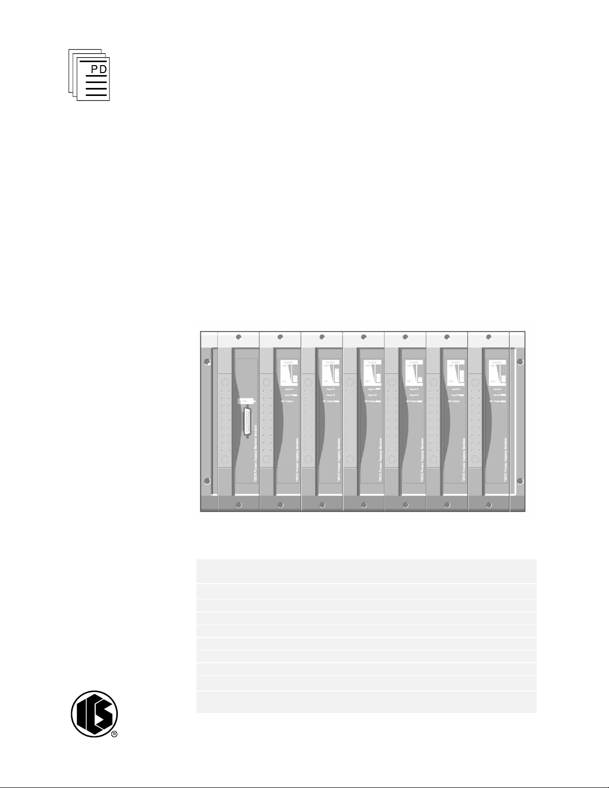
The power supply assembly (see Figure 1) converts redundant main-line
voltages of either 110-240 VAC or 24 VDC to +15 VDC or +24 VDC
ou
tput power for ICS product power requirements.
March, 06
Industrial Control Services
Figure 1. Power Supply Assembly
Features
·
Redundant power inputs
·
250 W
·
Hot replaceable
·
Current sharing
·
Power factor correction
·
Front panel indicators for input, output voltage status and
output current level on each module
·
Ext
·
TÜV certified for safety, Risk Class 5
1
ernal status signals
Page 2

Catalog No.
Chassis Unit
Input Power Voltage
Configuratio
n
T8200
I/O Power Supply Chassis
110-240 VAC, 50/60 Hz
Straight Bussed
T8201
I/O Power Supply Chassis
110-240 VAC, 50/60 Hz
Cross Bussed
T8202
I/O Power Supply Chassis
24 VDC
Catalog
No.
Input
Type
Input Power
Voltage
Output Power
Voltage
T8220
Dual 110-240 VAC
15 VDC
T8222
Dual 24 VDC
15 VDC
T8223
Single 110-240 VAC
24 VDC
T8224
Single 110-240 VAC
15 VDC
T8225
Dual 110-240 VAC
24 VDC
T8226
Dual 24 VDC
24 VDC
I/O Power Supply Assembly (T8060,T8062)
Structure
The power supply assembly consists of a power supply chassis containing
up to six power supply modules. The chassis may be configured to
distribute power in various combinations. For example, a chassis containing
six power supply modules may be set up with three modules providing
triplicated power for Regent+Plus I/O assemblies and three modules
providing field power in a N+1 configuration.
Power Supply
Chassis
The power supply chassis houses a maximum of six power supply modules.
It may be mounted in a 19-inch rack or flush mounted on a panel. Table 1
identifies the available types of chassis.
Table 1. Chassis Types
Power Supply Modules
The power su
pply assembly modules are single (if redundant inputs are not
required) and dual input, hot swap, user-replaceable AC and DC units.
Table 2 identifies the available types of modules.
Table 2. Module Types
2
Industrial Control Services
Page 3
I/O Power Supply Assembly (T8060,T8062)
PFC
PFC
Power Supply Module
PWM
Switching Regulator
T1:a
T1:c
T1:b
Rectifier
Rectifier
DC
Output
I/P Filter & Protection
I/P Filter & Protection
PFC A Off
I/P A Fail
PFC A Fail
Source
A
Source
B
Fail
High Tempterature
Reset
O/P Current
Status & Control
Remote Off
PFC B Off
I/P B Fail
PFC B Fail
Status & Control
Power Supply Module
DC
Output
I/P Filter & Protection
I/P Filter & Protection
PWM
Switching Regulator
T1:a
T1:b
I/P A Fail
Fail
High Tempterature
Reset
O/P Current
Status & Control
Remote OffI/P B Fail
Status & Control
Source
A
Source
B
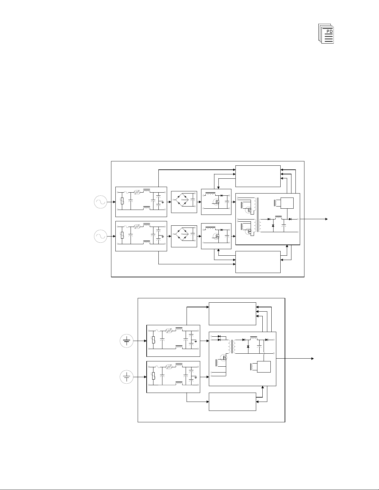
The dual inputs on the AC modules are galvanically isolated from each
other. The inputs on the DC modules are diode isolated and share a
common return.
Input Power Regulation
A block diagram of a typical dual AC input I/O power supply module is
shown in Figure 2. A block diagram of a typical dual DC input I/O power
supply module is shown in Figure 3.
Figure 2. Block Diagram of an AC I/O Power Supply Module
PD-6050
Figure3. Block Diagram of a DC I/O Power Supply Module.
Mar-06
3
Page 4

I/O Power Supply Assembly (T8060,T8062)
Each primary power input is individually fused and filtered with both
standard line filters and metal oxide varistors ( MOVs). The filters attenuate
any high-frequency common mode and normal mode noise present in the
power distribution system. The MOVs clamp high-voltage transients.
Filter, rectifier, and power factor correction circuits convert primary AC
input power to bulk DC voltage. The switching regulator converts bulk DC
power to regulated DC output voltage. Sensing, status, control, and timing
circuits provide for the following:
·
Input power failure - Active low status output. Indicates when the
input voltage is below 85 VAC or 18 VDC. There is a separate signal
for each input.
·
Bulk power failure - Active high status output on AC input modules
only. Indicates the DC bulk voltage (PFC output) is outside the
specified range. There is a separate signal for each input.
·
High-temperature warning alarm - Both an active high and active
low status output are provided. Indicates the module temperature
exceeds 75°C. The temperature is sensed near the air inle
the module.
·
High-temperature shutdown - Internal signal that will shut down the
t (bottom) of
switching regulator if module temperature is above 85 °C. The
temperature is sensed near the air inlet (bottom) of the module.
·
Output overvoltage - Internal signal that will shut down the switching
regulatorif the output voltage exceeds +18 VDC or +28 VDC for 15
volt and 24 volt modules respectively. Over-voltage protection circuitry
activation is a permanent error condition, requiri
to return module to normal operation.
·
DC output fail - Active high status output indicates the DC output
ng manual intervention
voltage has gone out of regulation. The DC output fail threshold is
13.75 VDC and 21.75 VDC (±0.25 VDC) for the 15 and 24 volt
module respectively.
·
Output current limiting - Internal signal limits output current in
excessive current demand situations.
4
Industrial Control Services
Page 5

I/O Power Supply Assembly (T8060,T8062)
·
POWER FAIL - Active high status signal that indicates impending loss
of output power due to one
-
Both inputs have indicated power failure
-
Remote off control signal activated
-
Thermal shutdown
-
Output overvoltage
·
RESET - Active high status signal that is generated a minimum of 10
of the following:
ms (AC input module) or 0.5 ms (DC input module) after a POWER
FAIL signal. RESET remains asserted for 200 ms (minimum) after
module power-up.
·
PFC off - Active low input that turns off the power factor correction of
an individual input. This signal provides the capability to test the input
circuitry
monitoring the module fail signal
of a module by turning off each input independently while
·
Remote off - Active low input that turns off the output power of a
module.
Note: Bulk Power Fail, PFC Off and Remote Off are accessed through the
monitor module connector on the chassis backplane. The monitor module
connector allows for a future development of a monitor card that would
provide remote control and enhanced monitoring of the power supply
chassis.
Active low signals are not maintained while RESET is act
signals are open collector and require external pull-up resistors.
ive. All status
RESET is used in the Regent I/O transceivers for power system interlocking
within the I/O system. A power failure (either input power or module fault)
activates RESET and turns off the DC output front panel indicator.
The POWER FAIL and RESET signals are required for proper operation
of Regent I/O transceivers and I/O modules during power up, power down,
and loss of power. Refer to
connect these signals to a Regent I/O chassis.
Assembly Installation
for details on how t
o
PD-6050
Mar-06
Front Panel Indicators
The front panel of each I/O power supply module contains the following
indicators:
5
Page 6

I/O Power Supply Assembly (T8060,T8062)
· Input Power Voltage Indicator
Each green INPUT POWER indicator is lighted when the associated
input (Input A, Input B) is above the lower input voltage threshold.
· Output Power Display
The 10-segment LED indicator bar displays the approximate output
current level percentage (0 - 100%)
· Output Power Indicator
The DC Output indicator is lighted when the I/O p
ower supply
module's DC output is within tolerance. Out-of-tolerance conditions,
loss of input power or brown-out, and module failures turn off this
indicator.
6
Industrial Control Services
Page 7

I/O Power Supply Assembly (T8060,T8062)
TB3
J13
J15
TB1
J14
19"
10.5"
J1 J2 J3 J4 J6J5
J7 J8 J12J11J9 J10
Input
Crossover
Patch
TB4
TB2
Installation
Chassis Mounting
Figures 4 and 5 show the front and rear views of the power supply chassis.
Figure 4. Power Supply Chassis Front View
Figure 5. Power Supply Chassis Rear View
PD-6050
Mar-06
7
Page 8

Input Crossover Patch configured for no crossover,
source 1 and source 2 are connected to input A and
input B respectively for all modules slots.
6E5 6E6
6E7 6E8
6E3 6E4
6E1 6E2
Input Crossover Patch configured to swap source 1
and source 2 for modules slots 4 through 6. Source 1
and source 2 are connected to input A and input B
respectively for slots 1-3. Source 1 and source 2 are
connected to input B and input
A respectively for slots
4-6.
Terminal
No.
T8200
T8202
Source
1 N DC- B
2
L
DC+
3 N DC- A
4
L
DC+
6E6
6E5
6E7 6E
6E3 6E
6E1
I/O Power Supply Assembly (T8060,T8062)
Mounting flanges can be attached to either the rear or the front of the
chassis. This allows flush mounting the chassis to a panel or mounting in a
19-inch rack.
The input crossover patch is on the T8200 chassis only.
Backplane Versions and Module Keying
Connector placement on AC input modules and backplanes differ from DC
modules and backplanes. This prohibits insertion of the wrong input module
type into a backplane.
Module slots in a chassis can be individually keyed to only accept a module
of an particular output voltage.
Input Power Terminals: TB1, TB2 (#8 screw terminals)
8
Industrial Control Services
Page 9

I/O Power Supply Assembly (T8060,T8062)
Terminal No.
Module Slot
T8200, T8202
12 6
11 5
10 4
+ DC Output
9 3
8 2
7 1
6
5
4 1-6 DC Return
3
(terminals 1-6 are
2
Connected together on
1 Backplane)
Pin
J14
J15
Slot Signal
Slot Signal
1
2
All
Input ‘A’ Fail
3
All
Input ‘B’ Fail
4
All
Hi Temperature
5
1
Reset 4
Reset
6
1
Power Fail
6
Reset
7
2
Reset 4
Power Fail
Output Power Terminals: TB3, TB4 (
#6 screw terminals)
Status Connectors: J14, J15
Type: 10 pin Shrouded Header, Double-Row, 0.100 x
0.100 Centers
Mfg.: AMP P/N: 102618-3
Mating Connector: AMP 87631-5
Pin Out:
PD-6050
Mar-06
9
Page 10

8
3
Power Fail
6
Power Fail
9
2
Power Fail
5
Power Fail
10 3
Reset 5
Reset
Available Load Units (for a set of 3 power supplies)
Number of I/O Units (Chassis):
Load Unit Capacity:
1 2
3
4
82 78 74 70
I/O Power Supply Assembly (T8060,T8062)
Monitor Connector: J13
Configuration
Current Sharing
The modules are capable of current sharing by connecting their outputs
together in parallel. This can be done external to the chassis or by using a
shorting bar that mounts directly to the output terminals on the chassis
backplane. This allows separate gro
chassis to have their outputs configured as: Single, Dual or N+1. The
module uses a passive “droop” method of current sharing and will share to
within 25% of the rated load.
Regent Power Supply Load Units
Type: 72 pin Edge Connector, 0.125” centerline
Mfg.: AMP
Mfg. P/N: 1Pin Out: TBD
530844-9
ups of modules from within a single
When using the power supply system with Regent and Regent+Plus , power
supply loading is based on the number of I/O modules in the I/O chassis
and the load imposed by each I/O module. Load units for each I/O module
are shown in that module’s product description and spec
under the
will provide the following load units:
10
Safetybus Power
ification sheet
heading. A set of three power supply modules
Industrial Control Services
Page 11

I/O Power Supply Assembly (T8060,T8062)
Calculating the number of load units in your system helps you to determine
the number of I/O power supplies your system needs. For economic power
distribution, and to avoid overloading individual power supply units,
calculate power supply loa
ding when configuring systems.
Regent I/O Triplicated Power Distribution
A chassis can contain two sets of triple-redundant power supplies for
Regent I/O. Each of the triple-redundant I/O power supply modules within
the I/O power supply chassis provides power for one leg of the three
redundant legs of the I/O Safetybus transceivers, and provides power to all
the I/O modules within its associated I/O chassis. Each I/O module contains
a diode OR power-sharing circuit that receives power from all three I/O
pow
er supply modules.
Should any I/O power supply module fail, only one leg of the transceiver
modules loses power: the two remaining legs maintain proper Regent
operation. In addition, all the I/O modules continue to operate properly by
drawing their current from the two remaining power supplies within the I/O
power supply assembly.
I/O transceivers and I/O modules require power fail and reset status signals
for proper operation.
PD-6050
Mar-06
11
Page 12

TB3
J15
J14
6
6
{
Two Sets of Triplicated Power
and Status to Regent I/O
Chassis
{
IInput
Crossover
Patch
123
45678
91011
12
T8200 Chassis
Source B
Source A
TB3
J15 J14
10
{
Triplicated 15 Volt Power and
Status for Regent I/O Chassis
Input
Crossover
Patch
1
2
3
4
5
6
7
8
9
10
11
12
T8201 Chassis
Source B
Source A
T8220 Dual AC Input, 15 VDC Output
T8220 Dual AC Input, 15 VDC Output
T8225 Dual AC Input, 24 VDC Output
T8223 Single AC Input, 24 VDC Output
Dual 24 V Power and Status for
Trusted ICS
24 V Power for Field Devices
{
{
6
4
T8220 Dual AC Input, 15 VDC Output
T8225 Dual AC Input, 24 VDC Output
TB3
J15
J14
6
{
{
IInput
Crossover
Patch
121110
98765
432
1
T8200 Chassis
Source B
Source A
N+1 Power For Field Devices
Triplicated Power and Status
For Regent I/O Chassis
I/O Power Supply Assembly (T8060,T8062)
Sample Chassis Configurations
Two Sets of Triplicated 15 V Regent Power
12
Triplicated 15 V Regent and Redundant 24 V Trusted ICS Power
Industrial Control Services
Page 13

I/O Power Supply Assembly (T8060,T8062)
Triplicated 15 V Regent and 24 V N+1 Field Power
Maintenance
No periodic maintenance or calibration is required for I/O power supply
modules. There are no user-replaceable parts.
A failed I/O power supply module can be hot-replaced without disrupting
system operations. Main power wiring and I/O power cables (connected
to the chassis) are not disturbed during module replacement.
Safety Considerations
The power sup
Risk Class 5 safety critical applications.
ply modules and chassis are TÜV certified for
PD-6050
Mar-06
13
Page 14

Voltage Range
T8220, T8223, T8224, T8225
T8222, T8226
85 to 264 VAC
20 to 30 VDC
Frequency Range
T8220, T8223, T8224, T8225
47 to 63 Hz
Inrush Current
(120/260 Vac)
T8220, T8223, T8224, T8225
20/40A (peak) Cold,
35/65A (peak) Hot
Power Factor
0.95 min.
Efficiency
70%
Use with Chassis
T8220, T8223, T8224, T8225
T8222, T8226
T8200
T8202
Fusing (Internal to module)
T8220, T8223, T8224, T8225
T8222, T8226
6A, 250 V, 3AG Slow Blow
20 A, 250 V, 3AB Slow Blow
Output Voltage
T8220, T8223, T8224, T8225
T8222, T8226
+15 volts
+24 volts
Output Power
250W, per module
Power Hold-up Time
T8220, T8223, T8224, T8225
T8222, T8226
20 msec, minimum
1 msec, minimum
Operating Temperature
Natural Convection
Forced Air (>20 lf/min)
-20°
to 50° C
-20°
to 70° C
Storage Temperature
-40°
to 85° C
(-40° to 185° F)
I/O Power Supply Assembly (T8060,T8062)
Specifications
14
Industrial Control Services
Page 15

I/O Power Supply Assembly (T8060,T8062)
Operating Humidity
0 to 95% relative humidity, non
-
condensing
Vibration
10 to 55 Hz:
±0.15mm
Shock
Operating:
15 g, ½ sine wave, 11 msec
Electromagnetic Interference
•
IEC 801 Part 2 - Electrostatic
Discharges
•
IEC 801
Part 3 - Radiated
Electromagnetic Fields
•
IEC 801 Part 4 - Transients
and Bursts
•
IEC 801 Part 5 - Surge
Immunity
•
ANSI/IEEE C37.90 - Surge
Withstand Capability
Level 3: Contact discharge of
6 kV
Level 3: 10 V/M, 27 MHz
-
500 MHz
Level 4: 2 kV, 2.5 kHz for
t = 60 sec
Level 3: 2 kV
2.5 kV damped 1 MHz sine
wave
4 kV bi-directional impulse, 10
nsec rise time, fast tran
sient
Safety
Certified to DIN V VDE 0801
for Risk Class 5. Also designed
to meet UL 508 and CSA 22.2,
No. 142-M1981
Module Dimensions
Height:
Width:
Depth:
10.47" ( 266 mm)
2.38" ( 61 mm)
12.5" (318 mm)
Chassis Dimensions
Height:
Width:
Depth:
10.47" ( 266 mm)
19" ( 483 mm)
13.5" (343 mm)
Specifications (Continued)
PD-6050
Mar-06
15
Page 16

Module Weight
6.9 lbs (3.2 kg)
I/O Power Supply Assembly (T8060,T8062)
16
Industrial Control Services
 Loading...