

Page 1

Trusted
TM
AN-T80017
Application Note
Regent to Trusted Migration
This document describes the steps needed to replace a Regent processor chassis with a Trusted
processor chassis. This replaces the Regent processor and communications modules and providing a
future path to expansion of the Trusted system side. It assumes a knowledge of Trusted application
design.
Issue Record
Issue
Number
1 June 08 Nick Owens Andy Holgate Pete Stock Initial Issue
2 June 08 Nick Owens Andy Holgate Pete Stock Corrections
Issue 2 June 08 AN-T80017 1
Date Revised by Technical
Check
Authorised by Modification
Page 2

Trusted
TM
AN-T80017 Regent to Trusted Migration
1. Hardware
The migration principles are identical for Regent (panel mount) and Regent +Plus (rack mount)
because the internal circuitry is the same, as is the software. In this document, the term ‘Regent’ is
used for both variants.
The Regent processor chassis with processor and communications modules is replaced by a Trusted
processor chassis with communications modules. The T8160 TMR Interface module (otherwise known
as the Regent interface module, or RIM) bridges the triplicated Regent Safetybus into the Trusted
Inter-Module Bus (IMB). The T8160 has a choice of two companion slot cables TC-320-01 and TC321-01. TC-320-01 ends in three connectors that fit the Regent chassis sockets. TC-321-01 ends in
three connectors that fit the existing Safetybus cables. This allows a choice of running new cables to
the first expander chassis or using the extra length of the existing cables.
The Trusted processor chassis is 6U high but also needs a 2U T8270 fan tray mounted above it. It
should not be located directly above bulk power supplies or other significant sources of heat, as air is
drawn from underneath the chassis.
A Trusted system requires one T8110B processor module (which contains three identical processors).
The chassis also has a companion processor slot to allow faulty processors to be replaced. For a
Trusted-Regent hybrid, one T8160 TMR interface module is required, and this is also fitted in a
companion slot, taking two of the eight single width slots. To replace the three Regent communications
modules, two Trusted T8151B communication interface modules are adequate. These each contain
four high speed serial ports and also two Ethernet ports. They support Modbus (master and slave) and
native Trusted peer networks, but will not support Regent Peer to Peer networks or the Regent
Guarded Peer link. Modbus Master requires a T8122 or T8123 Processor interface adapter.
Issue 2 June 08 AN-T80017 2
Page 3

Trusted
TM
AN-T80017 Regent to Trusted Migration
1.1. Parts List
T8100 1off Processor Chassis
T8270 1off Fan Tray
T8110B 1off Processor module (recommended spares holding of 1)
T8160 1off TMR Interface (recommended spares holding of 1)
T 8 1 5 1 B 2 o f f C o m m u n i c a t i o n s I n t e r f a c e
Optional T812x 1off Processor Interface Adaptor (T8120,1,2,3 as appropriate for IRIG and Modbus
Master licenses; see PD-T812X)
T8153 2off Communications Interface Adapter for serial and Ethernet connection
TC-320-01 1off Interface cable to plug into first Regent expander chassis OR:
TC-321-01 1off Interface cable to chain to existing cables
Recommended power supply for Trusted:
T8240 1off Power shelf for three Power Packs
T8231 2off 750W 24Vdc Power Pack
MCBs On AC (6A) and DC sides (20A)
Recommended replacement for Regent system power supplies is required (see PD-T8200 for options):
T8200 1off Power supply chassis (or T8201) (room for 6 modules)
T8220 3off Power supply module 15V (3off per 4 Regent chassis)
T8294 1off Supply adaptor board (1off per 4 Regent chassis)
Issue 2 June 08 AN-T80017 3
Page 4
Trusted
TM
AN-T80017 Regent to Trusted Migration
2. Electrical
The chassis and its modules are powered from a dual 24Vdc (nominal) supply, each supply providing
at least 250W through 20A MCBs.
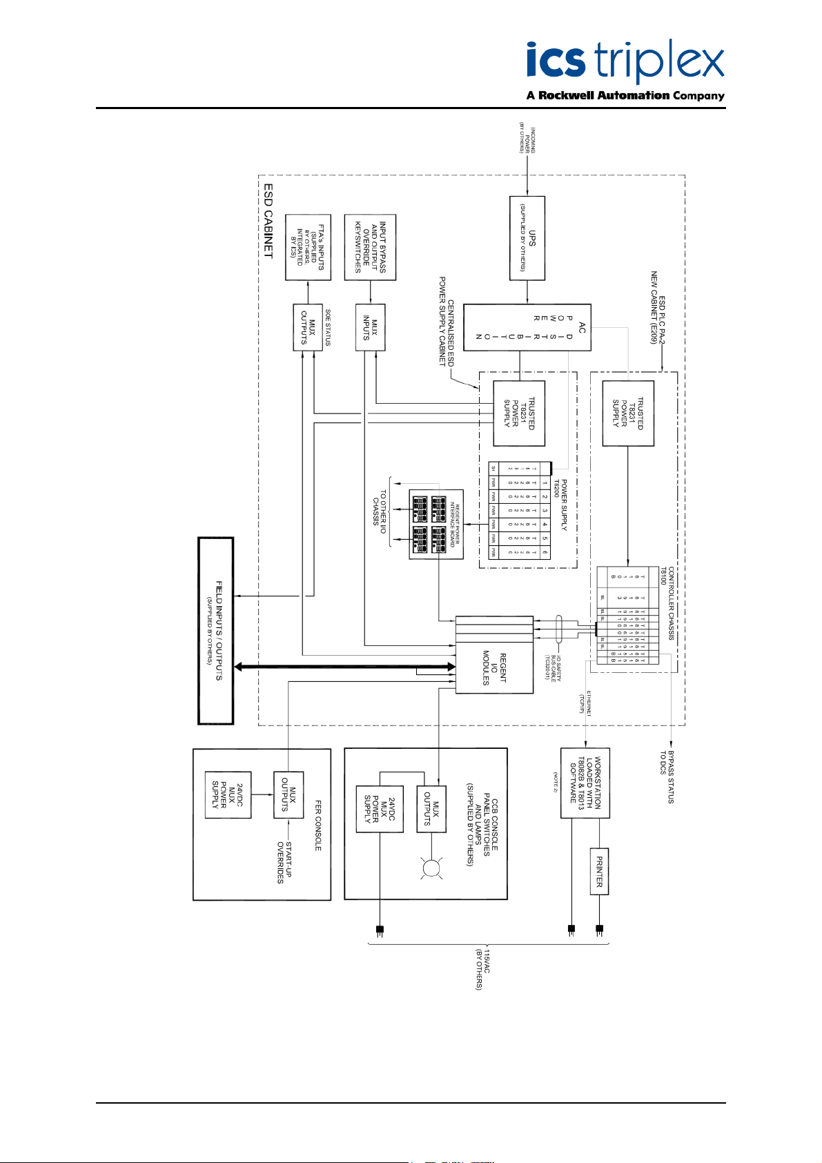
If the Regent system power supplies are to be replaced, the T8200 range is recommended. These
have 250W units in sets of three to match the Regent power needs. Regent chassis require extra
diagnostic signals to start the system once the supply has settled and to warn it of impending loss of
power, and the T8200 range provides these signals. An interface board T8294 is available to provide
connections to four Regent chassis, including the diagnostic signals.
In the example shown in Figure 2, the Trusted chassis is powered by T8240 power shelves containing
T8231 supplies, which also replace existing bulk supplies powering the general 24V requirements in
the system and field.
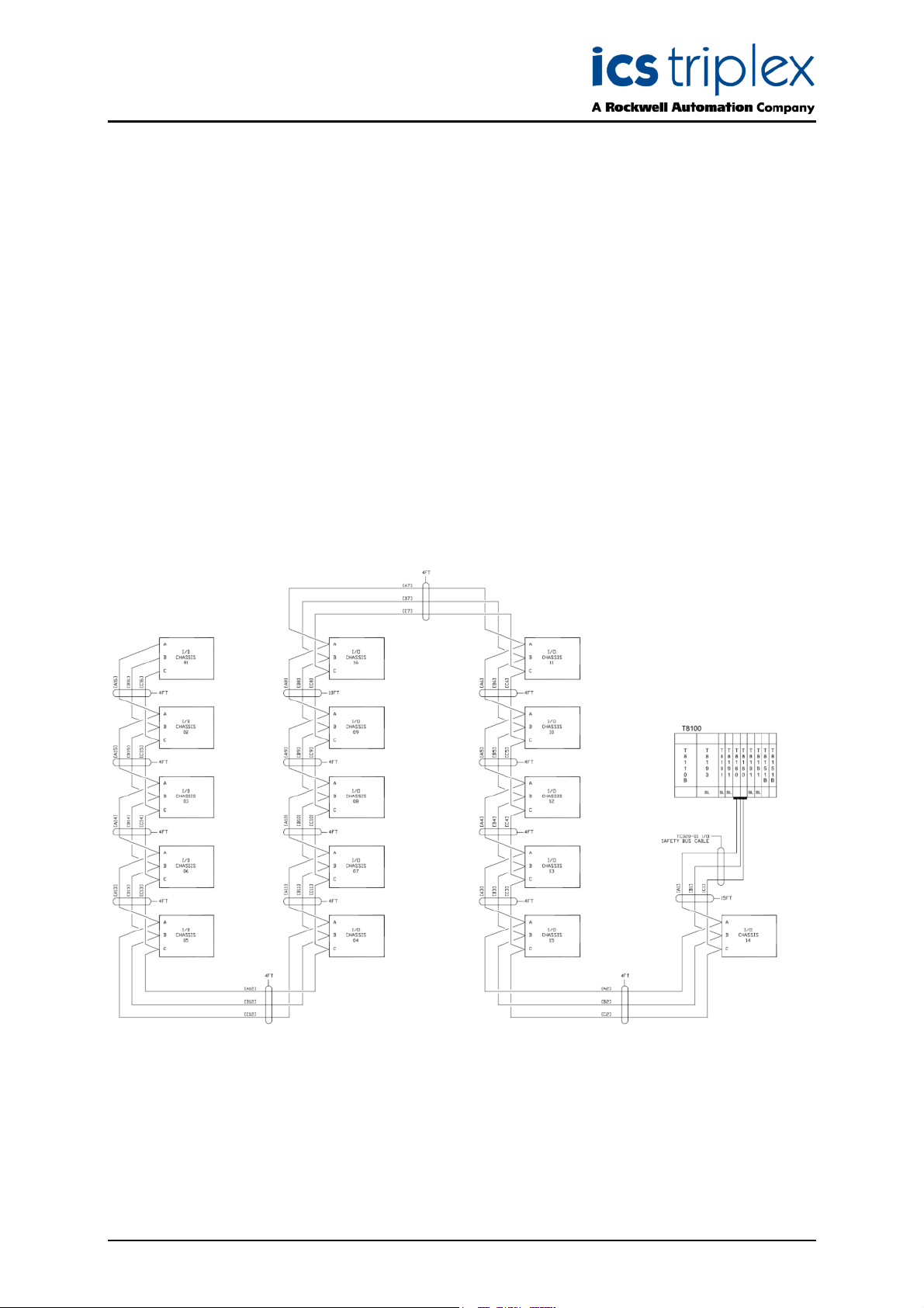
2.1. Communications
The T8160 connects to the nearest Regent chassis using a TC-320-01 cable as shown in Figure 1. It
can also be connected to the end of the original Safetybus cables to the processor chassis using a TC321-01 cable. This has connectors to match the existing cables. The existing chain of safetybus cables
is used to communicate with the remaining chassis.
Figure 1 Safetybus Wiring Example
Issue 2 June 08 AN-T80017 4
Page 5
Trusted
TM
AN-T80017 Regent to Trusted Migration
Figure 2 Example Power Supply Overview
Issue 2 June 08 AN-T80017 5
Page 6

Trusted
TM
AN-T80017 Regent to Trusted Migration
3. Installation
Both the Regent and Trusted are 3-2-0 degradation systems. When fully healthy, all three slices are
working (3). On one fault, the remaining two slices can continue operating as long as they agree (2).
On a fault in one of the two remaining slices, the system shuts down (0).
This provides higher integrity than 3-2-1-0 since at least two system slices must be operational for the
system to be operational, allowing instant and robust diagnostics through voted comparison. However,
since each system requires two of the three slices to operate, an online changeover is not possible and
the changeover must be made with the system in shutdown.
The new Trusted chassis may be fitted in place of an existing rack-mounted Regent+Plus processor
chassis if time is available for physical installation, or it may be fitted in spare space nearby whilst the
existing system is operating. The standard TC-321-01 cable is 4 metres long, but the existing Regent
Safetybus cables to the Regent processor chassis may also have slack inside trunking, or it may be
possible to route them differently to gain length.
Power the Regent I/O chassis first and allow them to start. Then power the Trusted processor chassis
with the Safetybus connected. If the Trusted application and system.INI are correct, the application will
start and the application can be commissioned.
Issue 2 June 08 AN-T80017 6
Page 7

Trusted
TM
AN-T80017 Regent to Trusted Migration
4. Application
There is no automated tool for application conversion from Regent to Trusted, and the applications are
very different. However, it is possible to copy the functionality with the resulting programs looking
similar to the original programs. Use the following steps to ease the process.
In this section, ‘Winterpret’ is used as the name of the Regent application tool. Its predecessor was
PDS, which is still in use on the older Regent systems. The presentation is different but the core
functionality is similar.
A copy of Winterpret (or PDS) will be necessary to read the Regent configuration. This does not need
to be the same issue as used before, but must be loaded with the same extra packages.
4.1. System Configuration
The System.INI file for a Trusted-Regent hybrid is very simple. Insert a T8160 TMR Interface into the
chassis, and insert another T8160 in its companion slot to the right. This allows the system to blackstart with the T8160 in either slot. By convention, slots 1 and 2 are used.
Insert T8151 communications interfaces into the chassis. By convention, slots 7 and 8 are used.
This leaves four slots spare for Trusted I/O modules and interfaces to future Trusted expansion I/O
chassis, which will have a much smaller panel space than the corresponding Regent I/O equivalent.
Configure the communications interface parameters. Replicate the serial port settings from Regent
(baud rate, bits and parity). For Modbus slaves, enable slaves on the ports as appropriate. For Modbus
Master, create a Modbus Master and define its slaves and messages as in the Regent application. For
further information, refer to product description PD-T8151B.
4.2. Toolset I/O Connection Table
The first step is to build the I/O connection table. Add definitions for modules in the Trusted chassis
first.
ttmrp Trusted processor Only one definition required
ttmri_ii TMR Interface One ttmri_ii definition covers both module positions
There is no need to add definitions for the communications interfaces. If the TMR Interface was not
placed in the left-hand slot of the eight narrow slots in the Trusted processor chassis, correct the Slot
number on each of the two boards of the ttmri_ii definition.
Now add the definitions for each Regent I/O module. It is recommended to place these definitions in
the order that they appear in the chassis and slots, but the only real constraint is that 7491 multiplexer
modules must be defined before their multiplexer I/O. Product description PD-T8160 describes each
definition. These definitions each provide connection boards for variables used in the application.
Each definition for a Regent module must be set up with the following parameters:
TICS_CHASSIS and _SLOT The chassis number (1) and the slot number (usually 1) of the
T8160 TMR Interface. (It helps here if the T8160 is in the default position, chassis 1 slot 1).
REGENT_CHASSIS and _SLOT The position of the Regent module; the first I/O chassis is
chassis 1.
There will be further parameters for the second and third module position in definitions applying to
multiple module sets.
Copy these parameters to the entry points on each board.
Issue 2 June 08 AN-T80017 7
Page 8

Trusted
TM
AN-T80017 Regent to Trusted Migration
Channel LEDs may be prevented from showing faults using the MONITOR_MASK as in Winterpret.
The digital input monitoring thresholds are also entered on board parameters, as are any other
parameters required in the Winterpret application.
4.3. Declaration of variables
In Regent, the Modbus address map is automatically assigned to variables according to their position
in the list. This often means that spare variables must be declared to fill in gaps between address
blocks. In Trusted, each variable is assigned an address separately, and so spare variables are not
necessary.
PD-T8160 describes the connection points available on each I/O module definition. These may be
different to Regent. For example, digital inputs in Regent can be read individually using digital shared
control relays and also as a 16-bit word using shared registers. The definitions in Trusted will arrange
the data differently, including differences for definitions connecting to single, dual and triple module
sets and for open and packed data.
4.4. Replacement of Scale function blocks
Winterpret applications can have SCALE function blocks which convert input signals (as 0-4095) into
engineering units, including square root extraction if necessary. These may be replaced using
conversion tables in the Trusted analogue dictionary. The values and data available to the Regent
application will be in the same format and scaling in the Trusted application.
4.5. Replacement of Ladder function blocks
Winterpret has a fixed grid for its ladder logic with ten columns, the last of which must be a coil output.
The Trusted Toolset can handle ladder programs in two different editors. The Function Block Diagram
editor can program ladder logic using a switch on the toolbar. In this editor, ladder elements can be
placed anywhere on the screen and wired together; the left-hand inputs must be wired from a power
rail element. Essentially this is function block diagram programming using elements that look and act
like ladder logic elements.
There is also a ‘Quick LD’ editor, which allows creation and insertion of ladder elements and rungs,
automatically arranging branches in a fixed format. This may prove quicker to some programmers, but
it does not allow the flexibility of FBD ladder arrangement.
Trusted FBD ladder is executed according to the hierarchy of inputs; a block will not execute until its
inputs are ready. The program execution will therefore work its way from farthest inputs through to final
outputs.
Regent ladder executes down each column in turn for each rung. It is possible to create logic which
relies on this execution order for its operation. Therefore be aware that Trusted FBD ladder may
interpret the execution order differently to Winterpret ladder. The FBD editor has an option ‘Show
Execution Order’ which numbers function blocks and outputs in the order they are executed. Moving
logic on the screen may change this order but it is best practice to separate rungs to force the
execution order because in either language, the rungs are executed in order from top to bottom.
Regent function blocks are described in the Regent Software reference manual. The most common
complication is timers. Winterpret has one timer block with inputs for ‘time’ (increment the
accumulator) and ‘enable’ (allow incrementing when true or reset the count when false). Usually these
inputs are shorted together, so it acts as a delay-on timer like Trusted’s TON, but they may be
separate. If separate, the timer will be part of a latch to define other actions like TP. It has two outputs
which are the permanent inverse of each other; the upper output goes true on timeout.
Issue 2 June 08 AN-T80017 8
Page 9

Trusted
TM
AN-T80017 Regent to Trusted Migration
4.6. FLOAT function blocks
These are very similar to Trusted structured text programs, and were designed to handle floating point
arithmetic. Winterpret ladder programs can only handle integer arithmetic. These may be replicated as
structured text in Trusted.
4.7. MODBUS MASTER function blocks
These are replaced by the Modbus Master editor in the Trusted system configurator, for the
appropriate communications interface. The basic structure of declared slaves and assigned messages
is the same.
4.8. SOE function blocks
These created event lists from a list of shared control relays assigned for SOE collection. These
function blocks are replaced with SOE boards in the I/O connection table. Similarly, Process Historian
function blocks are replaced with PH boards in the I/O connection table.
4.9. PID function blocks
PID blocks are replaced with ipid function blocks inside FBD programs, from the T8019 Process
Control package. Refer to PD-T8019 for details on their operation.
4.10. Program Load
Regent allowed the I/O table and shared variables to be loaded as a foundation, with programs of
function blocks loaded and controlled individually on top. Trusted only has one application download
and relies on online updates for modifications.
The Trusted application will only run when all I/O module definitions match the system as discovered.
On failure, the message ‘cannot open board’ will be shown for each failed board, giving the table row
on which the definition is placed.
4.11. Diagnostics
A Trusted-Regent hybrid is essentially a Trusted system with unusual I/O modules. The fault history is
replaced by entries in the processor event log (ls d). The fault table is replaced by diagnostic command
‘rio’. This provides tables of the configured and actual modules. It also provides tables of transient and
permanent faults in text form, replacing the yellow and red icons in the Winterpret fault table. To see
the command syntax, type ‘rio’.
The clock in Regent may be set in a pop-up window; the nearest equivalent in Trusted are the
diagnostic commands ‘fps q’ to display the clock and ‘fps d …’ to set the clock.
4.12. System variables
Regent has fixed tables of system diagnostic data which do not exist in Trusted. Equivalent Trusted
information can usually be found in the diagnostic boards on each module definition in the I/O
connection table.
Issue 2 June 08 AN-T80017 9
Page 10

Trusted
TM
AN-T80017 Regent to Trusted Migration
5. Application Examples
Figure 3 Regent I/O Module Configuration
Regent I/O configuration allows names to be applied to each I/O point and fault point which do not
appear in the shared variables (the equivalent of the Trusted dictionary). It also allows the naming of
16-bit registers to carry all I/O points or faults in one tag, as shown above. The I/O operation is
configured in the table (thresholds, redundant modules etc.).
Issue 2 June 08 AN-T80017 10
Page 11

Trusted
TM
AN-T80017 Regent to Trusted Migration
In Trusted, all variables must be named in the dictionary and then connected to the appropriate data
point on the board definition. The OEM parameters are used to specify the I/O operational parameters.
The board definitions also handle some of the voting required, e.g. there is only one DO board below
for both modules but two fault boards.
Figure 4 Trusted I/O Module Configuration
Issue 2 June 08 AN-T80017 11
Page 12

Trusted
TM
AN-T80017 Regent to Trusted Migration
The Regent multiplexer module is a special case. This has multiple sub-windows for each multiplexer
slave input or output board. Each multiplexed point can be given a name.
Figure 5 Regent Multiplexer Configuration
Issue 2 June 08 AN-T80017 12
Page 13

Trusted
TM
AN-T80017 Regent to Trusted Migration
The Trusted implementation for multiplexed I/O is to use many separate I/O definitions. The Regent
7491 module should be declared before the I/O boards. Again, OEM parameters are used to define the
board addresses.
Figure 6 Trusted Multiplexer Configuration
Issue 2 June 08 AN-T80017 13
Page 14

Trusted
TM
AN-T80017 Regent to Trusted Migration
Regent variables can be declared in the Shared Variables lists as Control Relays (Booleans), Registers
(integers) and Floating Point Registers (reals). Variables can also be declared in the I/O connection
table as the name of I/O data points, and even implicitly as local variables inside function blocks.
Trusted variables must all be declared in the dictionary lists and used in the I/O connection table and
programs.
Regent shared variables are addressed by their position in the list, e.g. the variables here are at
Modbus address 0600 onwards. Trusted variables may be allocated individual addresses or none at
all. Regent often requires spare variables to space out the addresses; these are not needed in Trusted.
Figure 7 Regent Shared Control Relays and the Trusted equivalent
Issue 2 June 08 AN-T80017 14
Page 15

Trusted
TM
AN-T80017 Regent to Trusted Migration
Winterpret shared registers and shared floating point registers are in separate lists. Trusted integers
and reals are all in the same list.
Figure 8 Analogue variables
Issue 2 June 08 AN-T80017 15
Page 16

Trusted
TM
AN-T80017 Regent to Trusted Migration
Winterpret allows multiple programs, each containing function blocks in different languages. Each
program may be loaded and controlled separately. Trusted applications have only one ‘program’
containing multiple ‘function blocks’ by comparison, though the descriptive terms are different.
Figure 9 Regent and Trusted programming hierarchy
Issue 2 June 08 AN-T80017 16
Page 17

Trusted
TM
AN-T80017 Regent to Trusted Migration
Regent ladder logic function blocks are on a fixed grid with 10 columns wide. Trusted FBD/LD
programs allow free design with user function blocks. These two programs are not identical in their
operation.
Figure 10 Ladder Logic and FBD Programs
Issue 2 June 08 AN-T80017 17
Page 18

Trusted
TM
AN-T80017 Regent to Trusted Migration
Regent is capable of floating point arithmetic in separate Math function blocks, using a structured text
language similar to Trusted ST. In this case, FBD has been used as its replacement.
Figure 11 Floating Point Maths
Issue 2 June 08 AN-T80017 18
Page 19

Trusted
TM
AN-T80017 Regent to Trusted Migration
Regent has scaling functions as a separate function block language. These may be implemented with
conversion tables or with programming in ST, or using FBD as implemented here.
Figure 12 Scaling functions
Issue 2 June 08 AN-T80017 19
Page 20

Trusted
TM
AN-T80017 Regent to Trusted Migration
Regent has a separate function block language for defining points to be collected by Sequence of
Events. In Trusted, the evented points may be configured as outputs and wired to SOE boards (there is
no native SOE on Regent I/O modules when in a hybrid system).
Figure 13 Sequence of Events
Issue 2 June 08 AN-T80017 20
Page 21

Trusted
TM
AN-T80017 Regent to Trusted Migration
Communication settings are very different, by definition of the different architecture. Regent can have
six ports which may be for diagnostics (COMM), text output (ASCII), Modbus slave or master or
Regent Peer network. Trusted does not need allocation of a diagnostic port, and does not implement
text output or Regent peer network. In this case, the ports are essentially unused.
Figure 14 Port Configuration
Issue 2 June 08 AN-T80017 21
Page 22

Trusted
TM
AN-T80017 Regent to Trusted Migration
Issue 2 June 08 AN-T80017 22
Page 23

ICS Triplex technologies and services are available worldwide.
Hall Road
Maldon Essex
CM9 4LA
UK
el: +44 1621 854444
T
Fax: +44 1621 851531
www.icstriplex.com
For technical support email: support@icstriplex.com
Sales enquiries: sales@icstriplex.com
Technology Driven Customer Led
 Loading...