

Page 1

Trusted
TM
AN-T80010
Application Note
Module Misallocation Check
Technical Alert TA20003 describes a rare situation where an I/O module may be allocated to an
incorrect application board definition on startup. The module may then appear to be in a different
chassis and slot location. The result of this is that a module’s channel connections may be allocated to
the wrong application variables.
This document describes how to check for module misallocation, using the Toolset’s online debugging
tools.
Issue Record
Issue
Number
1 Nov 07 Nick Owens Pete Stock Initial Issue
2 Nov 07 Nick Owens Pete Stock Gerry Creech Primary position
3 Feb 08 Nick Owens Pete Stock Gerry Creech Startup
Date Revised by Technical
Check
Authorised by Modification
Issue 3 Feb 08 AN-T80010 1
Page 2
Trusted
TM
AN-T80010 Module Misallocation Check
1. Module Misallocation Check
1.1. Online Toolset Connection
To connect to the system using the toolset, follow the following procedure.
Open the Toolset ( Start | All Programs | Trusted | Toolset )
Open the project for the system you will connect to by double-clicking on its name.
It is possible to connect to the system using either the processor’s front panel serial port or over
Ethernet via a communications interface. Before connecting to the system, check that the
communications port settings are correct. Select Debug | Link Setup. If you are using a TC-305
maintenance cable to connect to the processor’s front panel serial port, check that ‘Communication
port:’ is set to COM1 (or whichever serial port you are using on the PC). If you are using Ethernet,
check that TMR System is selected. This option is at the bottom of the list and you need to scroll down
one row to see it. For Ethernet, click on Setup and check the IP address is set. For existing site
systems, the communications settings should already be set up.
Check that the maintenance cable is plugged into the PC serial port and the processor’s front panel
port (for serial connections) or that the system and PC are connected to the Ethernet network with
addresses on the same subnet (for Ethernet connections).
Ensure the processor keyswitch is turned to ‘Maintain’. The toolset will not communicate with the
system if the keyswitch is in the ‘Run’ position.
Select Debug | Debug. A long thin window entitled IEC1131 TOOLSET – (application) – Debugger
should appear. This will have a bold black line of text giving the state of the application. This window is
called the Debugger window and it is the key to all online controls. To disconnect from the system,
close this window and all other online windows will also close.
If the black line of text does not say RUN, and the system is clearly running (flashing ‘Run’ LED on the
processor), then there is likely to be a communications problem.
Using a serial port, you will see ‘Disconnected’. Check that the keyswitch is set to Maintain and the
maintenance cable is connected. Then try to connect again.
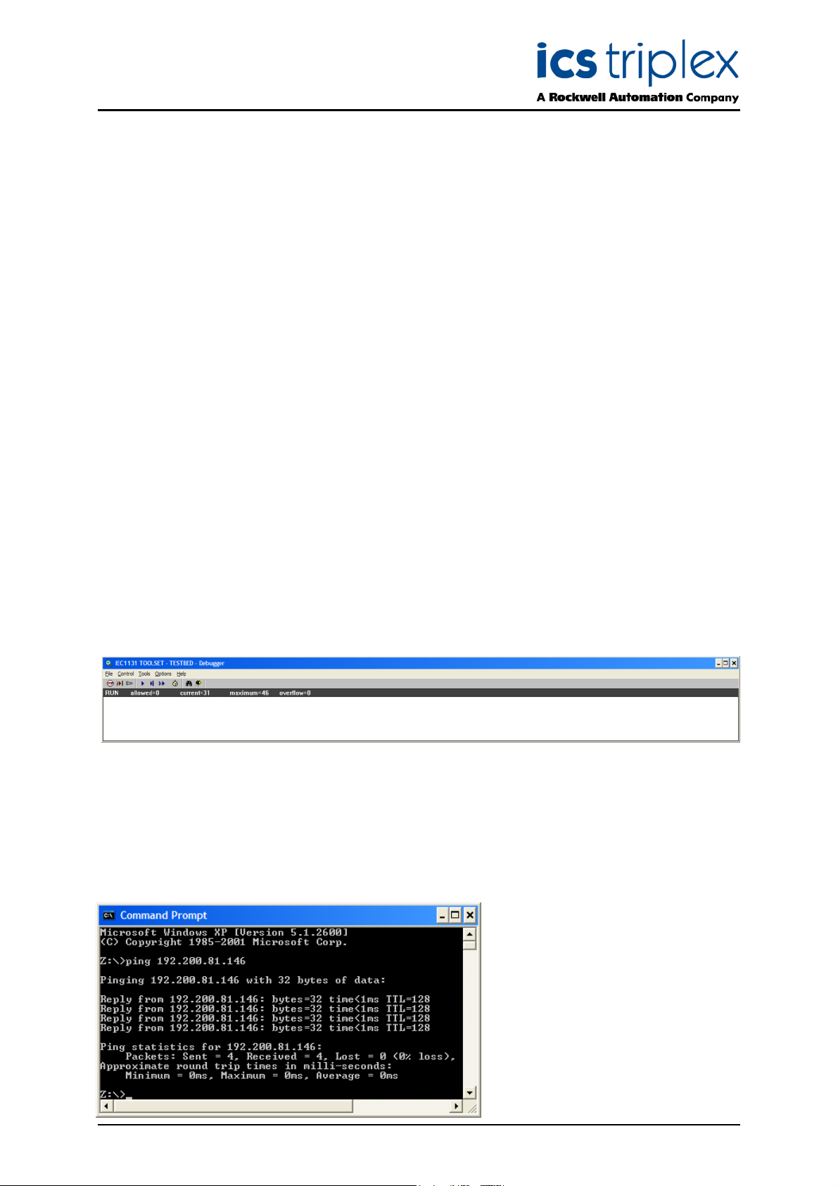
Using Ethernet, the online session will abort with the message ‘Cannot install the communication’. You
will need to close down all Toolset windows to reset this error. Check the keyswitch position. Check
that the Ethernet network is connected by sending a ‘ping’ command to the communications interface
port using the following command (with
the appropriate IP address) in a
command window. Then try to connect
again.
Issue 3 Feb 08 AN-T80010 2
Page 3

Trusted
TM
AN-T80010 Module Misallocation Check
1.2. I/O Connection table
To open the I/O connection table, use the window entitled IEC1131 TOOLSET – (application) – Debug
programs. You cannot close this window. To end an online session, close the Debugger window.
The I/O connection table can be opened using the same method as offline: either click the ‘cards’ icon
or Project | I/O connection.
Each module in the system has an equipment definition. Imagine this as a marshalling terminal rail,
with several blocks of terminals. These terminals are shown as icons appearing like screws, in several
different terminal blocks called boards. Each board is used to send data to or from the module, and
some of it is useful for diagnostics.
1.3. Module Allocation Check
Each equipment definition is allocated to a chassis and slot position where the module is. Click on the
first board in the definition (for the t8431 shown, click on THRSHIN). At the top of the connection data
is the chassis and slot position of the primary (default) slot as programmed in the application.
Now click on the INFO board, at the bottom of every equipment definition. The first two channels give
the chassis and slot position of the active (operational) module. If the active module is in the primary
slot, these will be identical to the programmed position. If the module is in the partner position or
running in a Smart Slot, the chassis and slot should reflect its location. Check the indicated position of
the active module on the system front panels.
Repeat this check for all Trusted
the advice given in Technical Alert TA20003. Note that I/O modules in the processor chassis are also
vulnerable to misallocation; in this case the processor should be started after the I/O modules.
Issue 3 Feb 08 AN-T80010 3
TM
I/O modules in the system. If any misallocation is discovered, follow
Page 4

ICS Triplex technologies and services are available worldwide.
Regional Headquarters:
Americas:
4325 West Sam Houston
arkway North, Suite 100
P
Houston
Texas 77043-1219
USA
Tel: +1 713 353 2400
Fax: +1 713 353 2401
Europe, ME & Africa:
Hall Road
Maldon Essex
CM9 4LA
UK
Tel: +44 1621 854444
Fax: +44 1621 851531
Asia Pacific:
Unit 2/12 Keegan Street
O’Connor
Western Australia
Tel: +61 89 314 7787
Fax: +61 89 314 7786
www.icstriplex.com
For technical support email: support@icstriplex.com
Sales enquiries: sales@icstriplex.com
Technology Driven Customer Led
 Loading...