

Page 1
Trusted
TM
AN-T80007
Application Note
Smart Slot Philosophy
For a Smart Slot configuration, the secondary slot is not required to be unique to each primary slot.
Instead, a single secondary slot can be shared among many primary slots. This technique provides
the highest density of modules to be fitted in a given physical space. Smart Slot between chassis can
be performed if the chassis are version 2 (or higher) as these have the connector fitted to enable
connection of a TC-006 that ensures the IMB 0V of each chassis is at the same potential.
Issue Record
Issue
Number
1 Nov 2004 Julia Bourn Initial Issue
2 Feb 2007 Nick Owens Ray Brown Peter Stock Format
Issue 2 Feb 07 AN-T80007 1
Date Revised by Technical
Check
Authorised by Modification
Page 2
Trusted
TM
AN-T80007 Smart Slot Philosophy
Implementation
Location of Smart slots
Design considerations should be given to the location of smart slots within the system. One option is to
allocate a spare slot on each chassis or per module type. Another option is to allocate one smart slot
per system panel; if this option is selected then the IMB 0V of each chassis needs connecting together
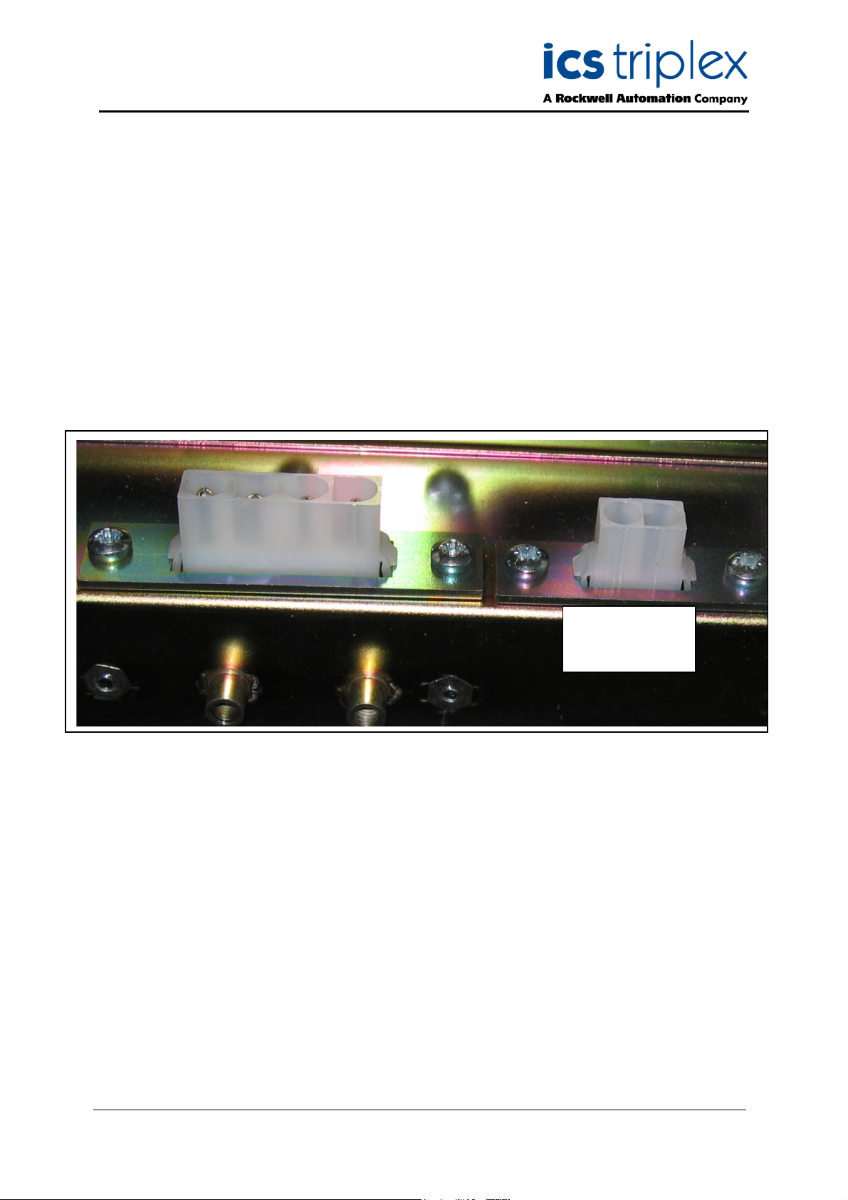
using a TC-006 cable. Each chassis (processor and expander) requires a TC-006 to connect to the
Molex socket on the back of each chassis and the crimps on the other end are taken to terminals that
are commoned together, this ensures that each isolated IMB 0v is at the same potential. Refer to PDTC000 for further information on TC-006.
Molex socket for
IMB 0V connector
TC-006
Figure 1 Molex Sockets on the rear of each processor and expander chassis
Issue 2 Feb 07 AN-T80007 2
Page 3

Trusted
TM
AN-T80007 Smart Slot Philosophy
Smart Slot Jumper cables
The Safety Manual requires that the Smart Slot jumper cables are tested before use.
The Smart Slot Jumper cables part numbers are as follows, refer to PD-TC300 for further information.
Input module Smart Slot jumper cable TC-306-02
Output module Smart Slot jumper cable TC-308-02
A Zone Interface module, that can be configured as both inputs and outputs, uses an output type smart
slot cable.
The length of the jumper cable is 2.5m, therefore it is not practical to smart slot between bays.
Spares
To maintain an available smart slot it is necessary to return a healthy module to the primary position.
This requires two types of each I/O module to be held as spares.
Operation
Smart Slot replacement (changeover) is effected by following the procedure detailed below.
Remove dust cap from the hood of the field cable at the rear of the faulty module.
Bridge the faulty module and Smart Slot positions by connecting the Smart Slot jumper connector to
the exposed ‘C’ type connector on the rear of the faulty module I/O connector.
Insert a serviceable module of the correct type, with compatible firmware and hardware, in the Smart
Slot position. The TMR Processor will verify that the module is the correct I/O module type and that
both Module Removal levers (and hence micro switches) are closed.
The TMR Processor will automatically initiate the education of the replacement module with the
appropriate data. The active module is then placed in the maintain state (which suspends field loop
testing), and any module specific changeover data is transferred. The Educated light flashes amber
before the active/standby changeover takes place, to indicate transfer of dynamic change over data
(COD).
When education is complete, the LED will adopt the steady green state, the previously active faulty
module will indicate ‘standby’ and the replacement module will indicate ‘active’. Check that the
remaining LEDs on the front panel of the replacement module are healthy.
The faulty module should be removed from the system and repaired.
To revert the system to its base configuration this procedure should be repeated in reverse. A
serviceable module should be installed in the original slot. Changeover may be initiated by opening the
ejector levers on the currently active module, i.e. the module occupying the Smart Slot, when both
Module Removal switches are opened on an active module, regardless of the module fault status, the
TMR Processor will treat it as a request to perform an active/standby changeover.
When the changeover is complete, remove the module in the Smart Slot position. Then disconnect the
Smart Slot connector. Do not remove the jumper cable before removing the Smart Slot module.
Notes
A module in the active state should never be removed.
Issue 2 Feb 07 AN-T80007 3
Page 4

ICS Triplex technologies and services are available worldwide.
Regional Headquarters:
Americas:
4325 West Sam Houston
arkway North, Suite 100
P
Houston
Texas 77043-1219
USA
Tel: +1 713 353 2400
Fax: +1 713 353 2401
Europe, ME & Africa:
Hall Road
Maldon Essex
CM9 4LA
UK
Tel: +44 1621 854444
Fax: +44 1621 851531
Asia Pacific:
Unit 2/12 Keegan Street
O’Connor
Western Australia
Tel: +61 89 314 7787
Fax: +61 89 314 7786
www.icstriplex.com
For technical support email: support@icstriplex.com
Sales enquiries: sales@icstriplex.com
Technology Driven Customer Led
 Loading...