

Page 1
Regent + Plus
PD 7901
I/O Termination Assembly (ITA)
RH/LH Varelco Connector and Screw
Terminal Versions
(T7901, T7902 and T7903)
Issue 1,
I/O Termination Assemblies (ITAs) are used in conjunction with I/O
modules to enhance the field wiring philosophy of the Regent + Plus
product range. The ITAs provide connector type conversion, analog
conversion, panel break facilities and an ideal point for test signal
injection. The ITAs can provide these facilities for all I/O modules with
the exception of the Thermocouple, RTU, Relay and Isolated Guarded
Output modules, which are wired in a conventional manner.
March, 06
Features
·
Rapid connection between I/O chassis and customer field
devices
· Optional current to voltage convers
· Provides supply and return paths for field devices
· Right-hand Varelco version - T7901
· Left-hand Varelco version - T7902
· Screw terminal version (high voltage) - T7903
· Provides panel break facilities
· Uses standard cables
· Fault tolerant configurable
The ITAs provide rapid connection between I/O chassis and customer
field wiring, using pre-formed cables which are wired on a one to one
basis (ie. module pin 1 to ITA pin 1). A common supply path is
provided, allowing common field/ret
resistors.
ion for active field devices
urn and analog conversion via
Industrial Control Services
1
Page 2
I/O T
ermination Assembly
A Varelco version has been developed for low voltage applications and
a screw terminal version for low and high voltage applications. Both
types of ITA are TÜV Certified.
Only one ITA is required per redundant slice. There are three types of
ITA:
· Varelco Connector Right Hand (Product Group T7901). Provides
connection for low voltage right hand cable entry terminations. A
typical example is shown below:
· Varelco Connector Left Hand (Product Group
T7902). Provides
connection for low voltage left hand cable entry terminations. A
typical example is shown below:
2
Industrial Control Services
Page 3
I/O Termination Assembly
· Screw Terminal (Product Group T7903). Provides screw terminal
connection for low and high voltage applications. A typical example
is shown below:
Each of the above has build variants to match the mode of operation of
the individual Regent + Plus I/O modules:
· Differential, Field Loop
· Differential, Field Loop with Dioded Power Protection
· Single Ended, with No Current Limiting in Field Loop
· Single Ended, with No Current Limiting in Field Loop with Dioded
Power Protection
· Single Ended, with Current Limiting in Field Loop with Dioded
Power Protection
· Single Ended, Analog, Current Mode
· Differential, Analog, Current Mode
· Single Ended, with External Current Limiting (Floating Earth
Systems)
Please refer to the Appendices for details of each build variant.
The ITAs are a standard size (170mm x 110mm) enabling a set area
in the back of each panel to be allocated for ITA placement. ITAs can
be grouped in order of voltage, ITA type, field zone, etc.
PD-7901
March, 06
The ITAs are packaged in a DIN Rail mounting PCB Carrier to provide
rapid assembly.
The Varelco versions of the ITAs have space allowance for a 90-Way
hood to be used on the mounting half of the field marshaling cable.
3
Page 4
I/O T
ermination Assembly
The unused pins of the connector are tracked to a screw terminal on
the PCB to allow the field cables and hoods to be grounded if required.
Module Operation
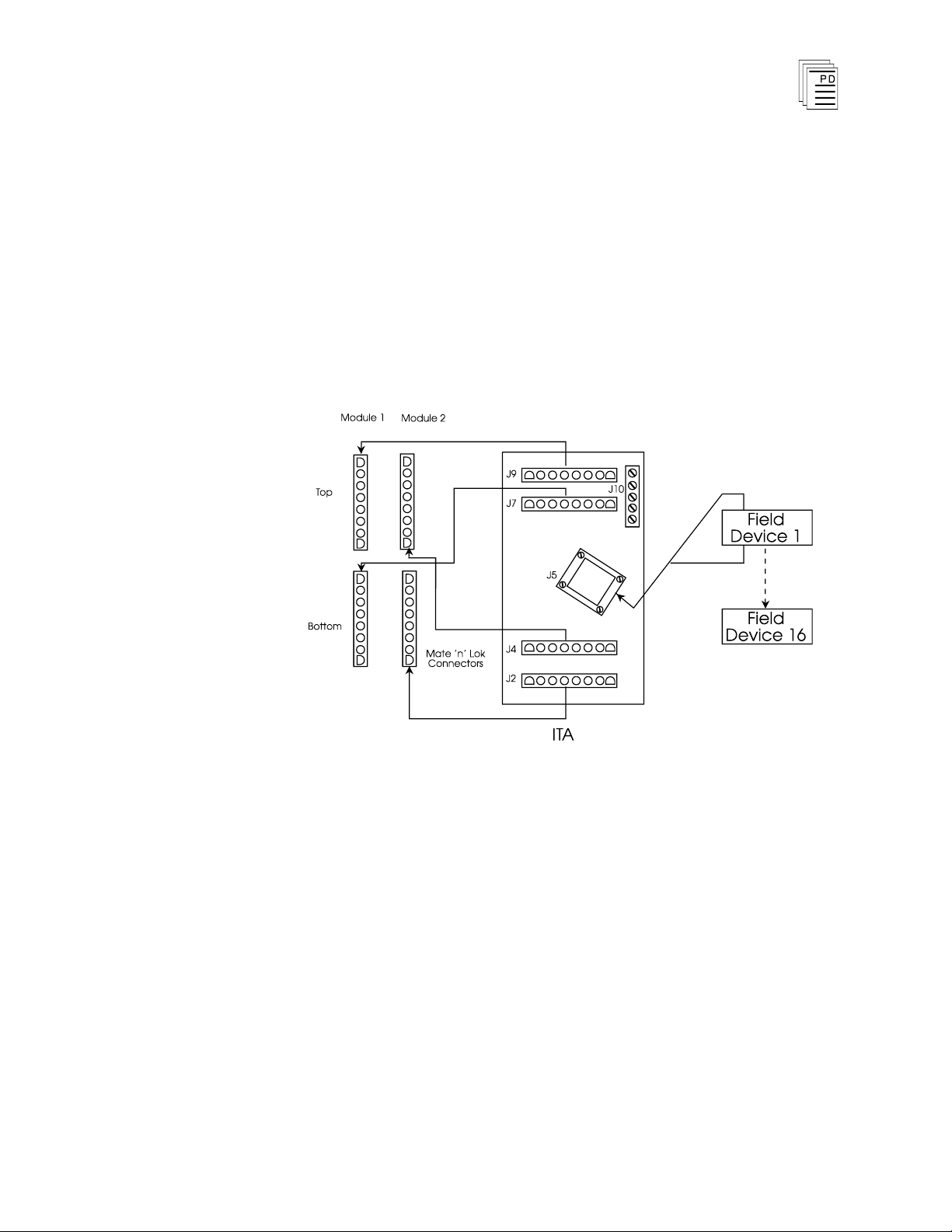
As shown below, pre-formed polarised I/O cables
between the I/O backplanes and ITA connectors
J1/J2/J3/J4/J6/J7/J8/J9. Field cables are connected to J5 and
common feed/returns and spare pin grounds are applied to connector
J10 (screw terminals). With a Screw Terminal ITA, connector J5
would consist of a set of dual row screw terminals.
are connected
4
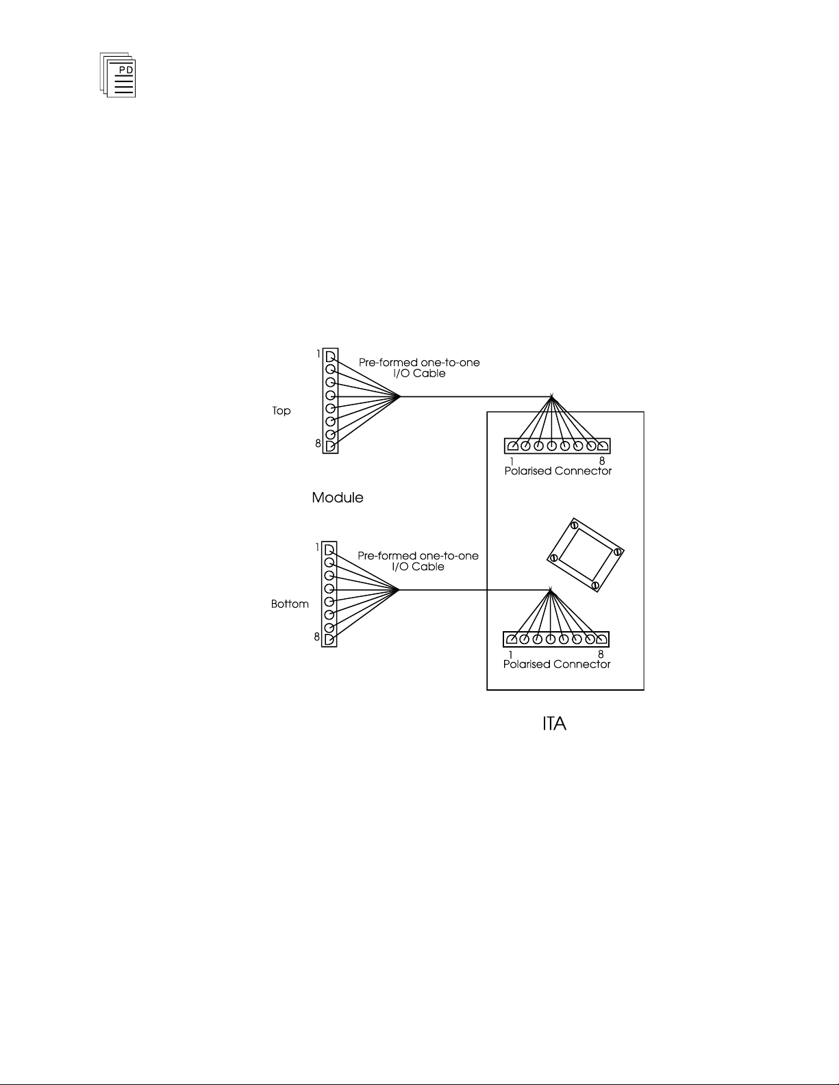
Pins 1 to 8 of the I/O Chassis 8-way connectors are wired one-to-one
with pins 1 to 8 of the 8-way connectors on the ITA. Each connector
on the ITA has pin identification shown on the l
Cross-mapping between the 8-way connectors on the ITA and the
Varelco/Screw terminals is shown in the appendices. Where field
sensor power is provided on single ended ITAs, the tables in the
appendices show the field power connections and distribution.
Industrial Control Services
egend of the ITA.
Page 5
I/O Termination Assembly
Module
ITA
Produc
t No
ITA Type
Comments
- -
Differential Field Loop
Refer to Appendix A
T7454
T7461A
T7
462A
T7468A
T7470
T7480
T7420A
T7420AF
790310
790110
790210
790110
790210
790310
790310
790110
790210
790110
790210
790110
790210
790110
790210
Screw Terminal Only
For voltages below
48Vdc
For voltages above 48V
dc
Screw Terminal Only
Differential Voltage Mode
Differential Voltage Mode
- -
Single Ended, No Current
Limiting Field Loop
Refer to Appendix B
T7464
T7481
T7484
T7488
T7411F
T7411
T7418F
790311
790111
790311
790311
790111
790211
790111
790211
790311
Screw Termin
al Only
Screw Terminal Only
Screw Terminal Only
Screw Terminal Only
Application
Table 1 shows the ITA type/variant to be used with each type of
Regent + Plus I/O module.
Table 1 - Module / ITA Type
PD-7901
March, 06
5
Page 6
I/O T
Module
ITA
Produc
t No
ITA Type
Comments
- -
Single Ended, No Current
Limiting Field Loop
Refer to Appendix B
T7444
T7401
T7402
T7408
T7404
T7441A
T7420A
T7420AF
790311
790111
790211
790111
790211
790311
790311
790111
790211
790111
790211
790111
790211
Screw Terminal Only
Screw Terminal Only
Screw Terminal Only
- -
Single Ended, Current Limiting
Dioded Supply
Refer to Appen
dix C
T7401
T7402
T7441
790112
790212
790112
790212
790112
790212
- -
Single Ended, Analog Current
Mode
Refer to Appendix D
T7420A
T7420AF
790113
790213
790113
790213
ermination Assembly
Table 1 (continued) - Module / ITA Type
6
Industrial Control Services
Page 7
I/O Termination Assembly
Module
ITA
Produc
t No
ITA Type
Comments
- -
Single Ended, External
Current Limiting
Refer to Appendix E
T7411
T7411F
T7418F
T7401
T7402
T7408
T7404
T7420A
T7420AF
790114
790214
790114
790214
790314
790114
790214
790114
790214
790314
790314
790114
790214
790114
790214
Screw Terminal only
Screw Terminal only
Screw Terminal only
- -
Differential Analog Current
Mode
Refer to Appendix F
T7420A
T7420AF
790115
790215
790115
790215
- -
Differential, Field Loop with
Dioded Power Protection
Refer to Appendix G
Special Projects
Future Use
- -
Single Ended, No Current
Limiting in Field Loop with
Dioded Supply
Refer to Appendix H
Special Projects
Future Use
Table 1 (continued) - Module / ITA Type
PD-7901
March, 06
7
Page 8

I/O T
ermination Assembly
Specifications
Electrical Specification
Power Supply Requirements:
T7901 & T7902
T7903
Current Carrying Capacity: 16A Max (Total)
RFI Immunity:
EMC:
Mechanical Specification
Dimensions (mm) Varelco:
Dependent on I/O variant.
Maximum values are given for
reference.
Screw Terminal: 170D x 110W x 65H
48VDC
120VAC/DC
27 to 500MHz at 10V/m
(3 axes)
400A/m at 50Hz (3 axes)
170D x 110W x 65H
Connector:
Weight:
Operating Temperature:
Shock:
Vib
ration:
Relative Humidity:
H2S Exposure:
Varelco 8016 Series
Screw Terminal
GSED5/32
Various
0 to 60oC
1/2 sine wave 6ms period,
10G peak (3 times) 3 axes
10 to 20Hz 0.5mm pp, 20 to
55Hz 1.0G peak in 3 axes
0 to 95% non-condensing
1ppm for 1 year with no
damage
8
Industrial Control Services
Page 9
I/O Termination Assembly
Appendix A - Differential, Field Loop
YTMR790110
YTMR790210
YTMR790310
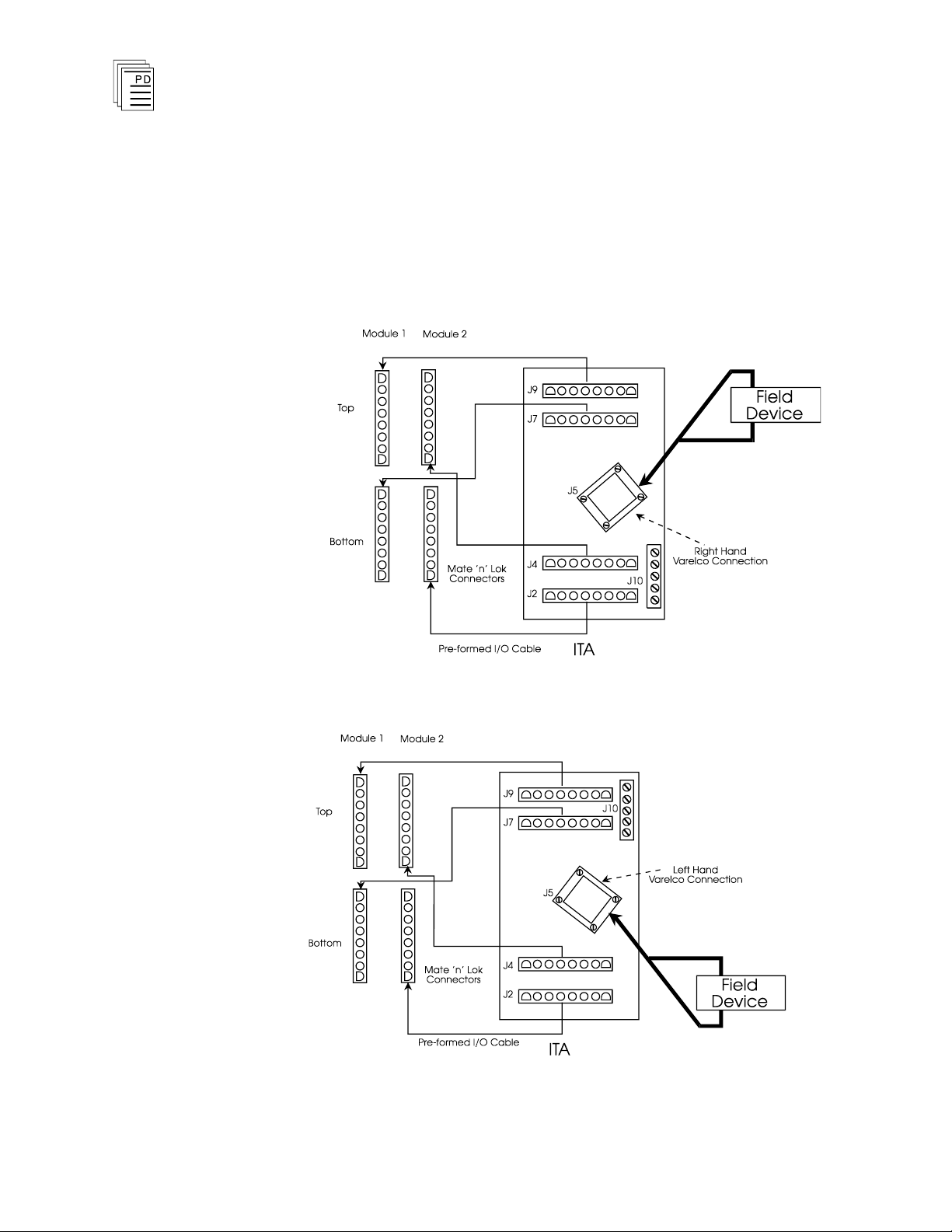
The Differential, Field Loop, ITA provides the facility to connect sixteen
differential field circuits to the I/O modules. One Differential, Field
Loop, ITA is capable of feeding two modules, as shown
diagrams below:
(Right Hand Varelco Connector)
(Left Hand Varelco Connector)
(Screw Terminal Connector)
in the block
PD-7901
March, 06
Figure A-1. Varelco Left Hand Differential,
9
Field Loop, Block Diagram.
Page 10
I/O T
ermination Assembly
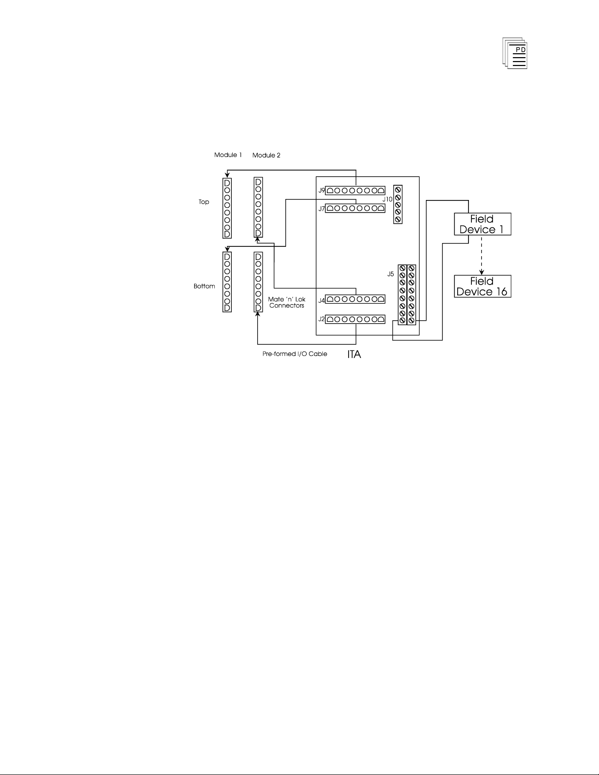
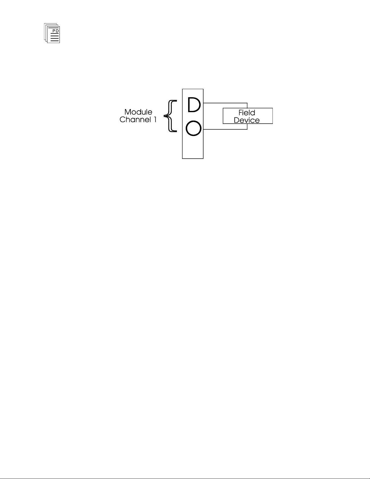
The modules which use the Differential Field Loop ITA are listed in
Table 1 of the main document. These modules function in a manner
such that the field devices do not require a common feed or return, as
illustrated below:
The connector idents are shown on the legend on the ITA.
10
Industrial Control Services
Page 11

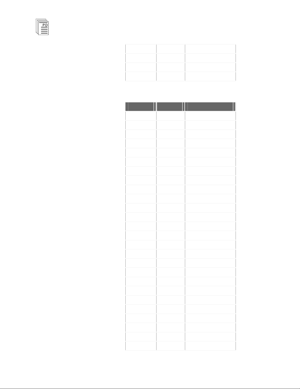
I/O Termination Assembly
Connector
Pin Ident
Connector (J5) Pin
J2 S1 C
J2 S2 D
J2 S3 H
J2 S4 J
J2 S5 M
J2 S6 N
J2 S7 S
J2 S8 T
J4 S1 A
J4 S2 B
J4 S3 E
J4 S4 F
J4 S5 K
J4 S6 L
J4 S7 P
J4 S8 R
J7 S1 AA
J7 S2 BB
J7 S3 EE
J7 S4 FF
J7 S5 KK
J7 S6 LL
J7 S7 PP
J7 S8 RR
J9 S1 Y
J9 S2 Z
J9 S3 CC
J9 S4 DD
J9 S5 HH
The four 8-Way connectors are tracked to the connectors. as shown
in Tables A-1 and A-2.
Table A-1. Varelco Connections.
PD-7901
March, 06
11
Page 12
J9 S6 JJ
J9 S7 MM
J9 S8 NN
J10 GND
U, V, W, X, SS, TT
Connector
Pin Ident
Connector (J5) Pin
J2 S1 3
J2 S2 4
J2 S3 7
J2 S4 8
J2 S5 11
J2 S6 12
J2 S7 15
J2 S8 16
J4 S1 1
J4 S2 2
J4 S3 5
J4 S4 6
J4 S5 9
J4 S6 10
J4 S7 13
J4 S8 14
J7 S1 19
J7 S2 20
J7 S3 23
J7 S4 24
J7 S5 27
J7 S6 28
J7 S7 31
J7 S8 32
J9 S1 17
J9 S2 18
I/O T
ermination Assembly
Table A-2. Screw Terminal Connections.
12
Industrial Control Services
Page 13

J9 S3 21
J9 S4 22
J9 S5 25
J9 S6 26
J9 S7 29
J9 S8 30
I/O Termination Assembly
PD-7901
March, 06
13
Page 14
I/O T
Connector
Ident
Pin Ident
Comments
J10
A
Connect to module
AREF1 & AREF2.
(T7420 only).
J10
B
Connect to AGND
(T7420 only).
J10
C
Connect to J10 (GND)
(T7420 only)
J10
D
No Connection.
J10
GND
Connect to ground if not
used on T7420. If used on
T7420, connect the Field
Analog Ground to Pin TT
of the Varelco Conne
ctor
and link J10 GND to J10
Pin C.
ermination Assembly
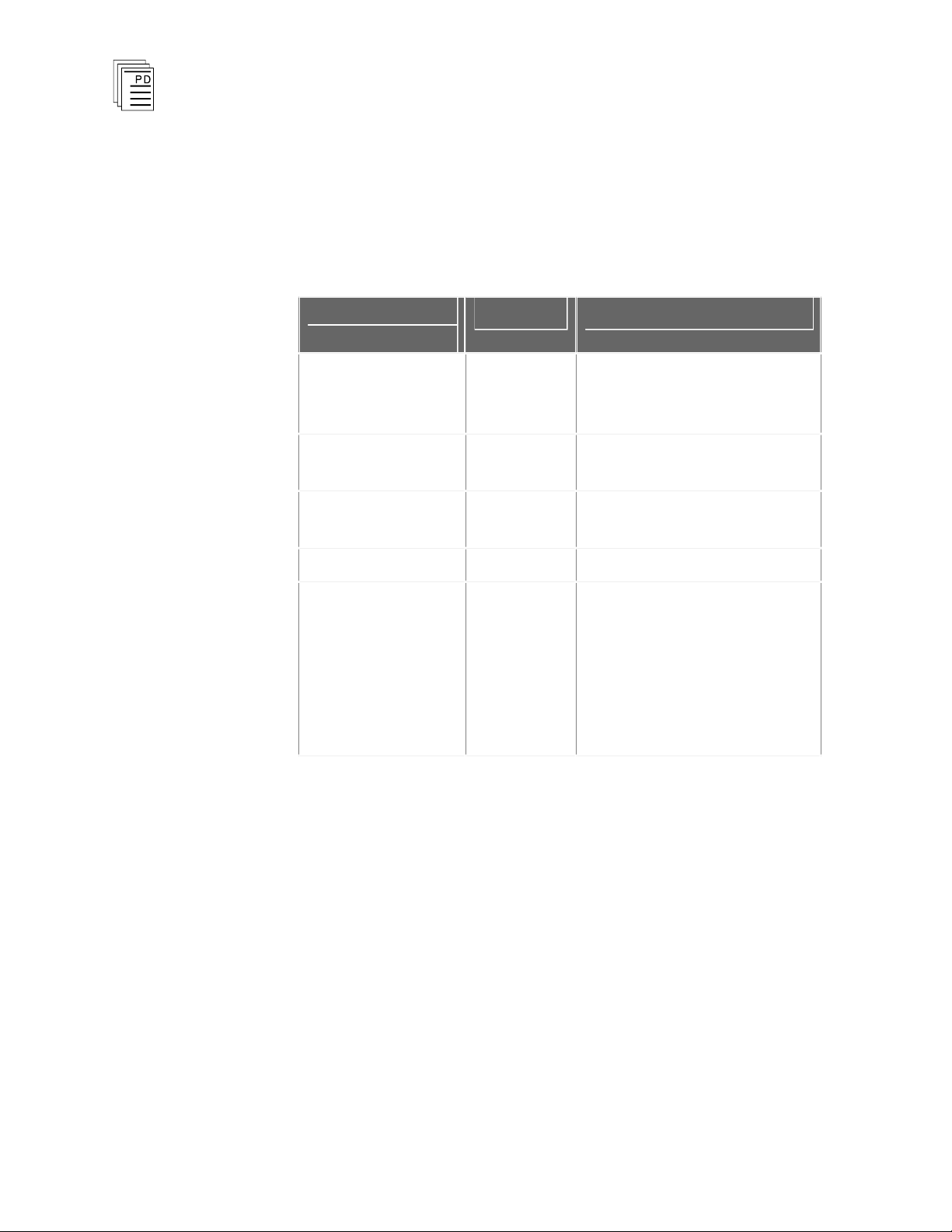
A set of five screw terminals on the Varelco variant of the ITA provides
the facility to ground the spare Varelco pins and for the reference
analog voltage to be connected to the I/O module (this facility
specifically concerns the T7420 Analog Input Module when it is used
with differential voltage input wiring). The detailed connections are
listed in Table A-3.
Table A-3. Varelco J10 Connection Details.
14
Industrial Control Services
Page 15
I/O Termination Assembly
Connector
Ident
Pin Ident
Comments
J10
A
Connect to
AREF1/AREF2.
(T7420 only)
J10
B
Connect to AGND.
(T7420 only)
J10
C
Connect to Analog Gr
ound
AINGD. (T7420 only)
J10
D
Connect Cable Screen and
Ground.
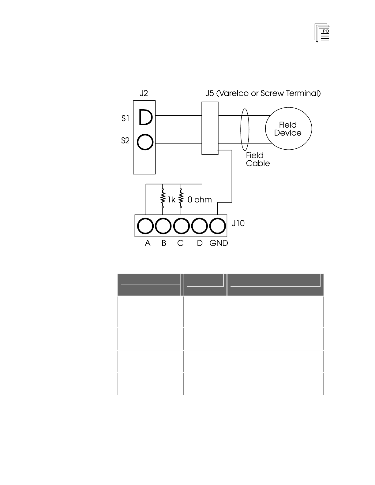
A set of four screw terminals on the Screw Terminal variant of the ITA
provides the facility for the reference voltage to be passed to the
T7420 Analog Input Module. A circuit schematic is shown below and
the detailed connections are listed in Table A-4.
Table A-4. Screw Terminal J10 Connection Details.
PD-7901
March, 06
15
Page 16
I/O T
ermination Assembly
Appendix B - Single Ended, No Current Limiting, Field Loop
YTMR790111
YTMR790211
YTMR790311
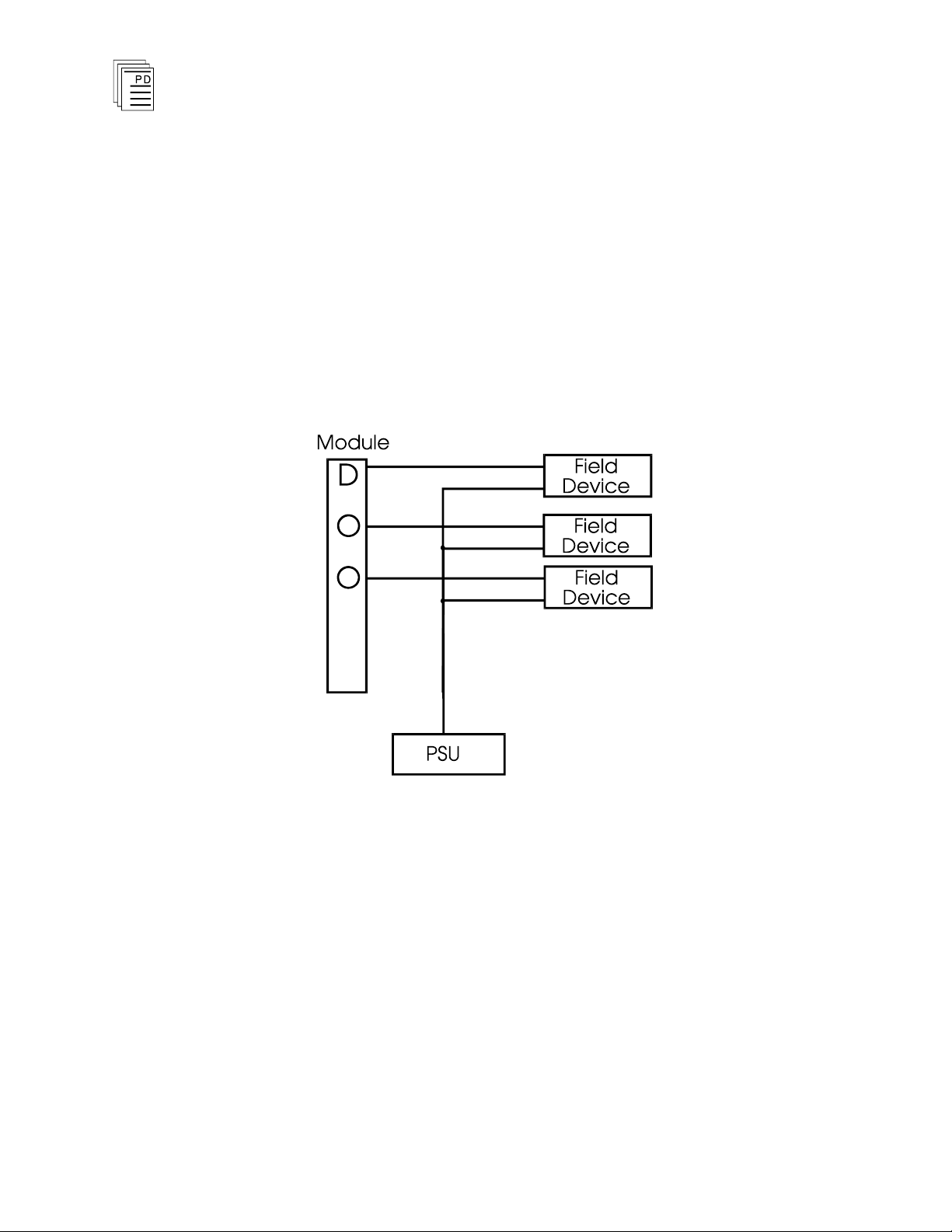
The Single Ended, No Current Limiting, Field Loop ITA provides a
method for supplying a common feed/return path to field devices on a
per module basis, as shown below:
(Right Hand Varelco Connector)
(Left Hand Varelco Connector)
(Screw Terminal Connector)
16
The single ended signal is fed from the I/O chassis to the ITA. The ITA
p
rovides a common supply which is tracked out on the ITA to provide
each single ended signal with a feed/return supply path. Each field
loop is capable of carrying 2A. The overall maximum current of the
ITA should not exceed 16A total.
Single ended I/O modules have 16 field circuits and one ITA will be
required for each module.
The connector idents are shown on the legend on the ITA.
The block diagrams below show typical connection of the module to
the field device.
Industrial Control Services
Page 17
I/O Termination Assembly
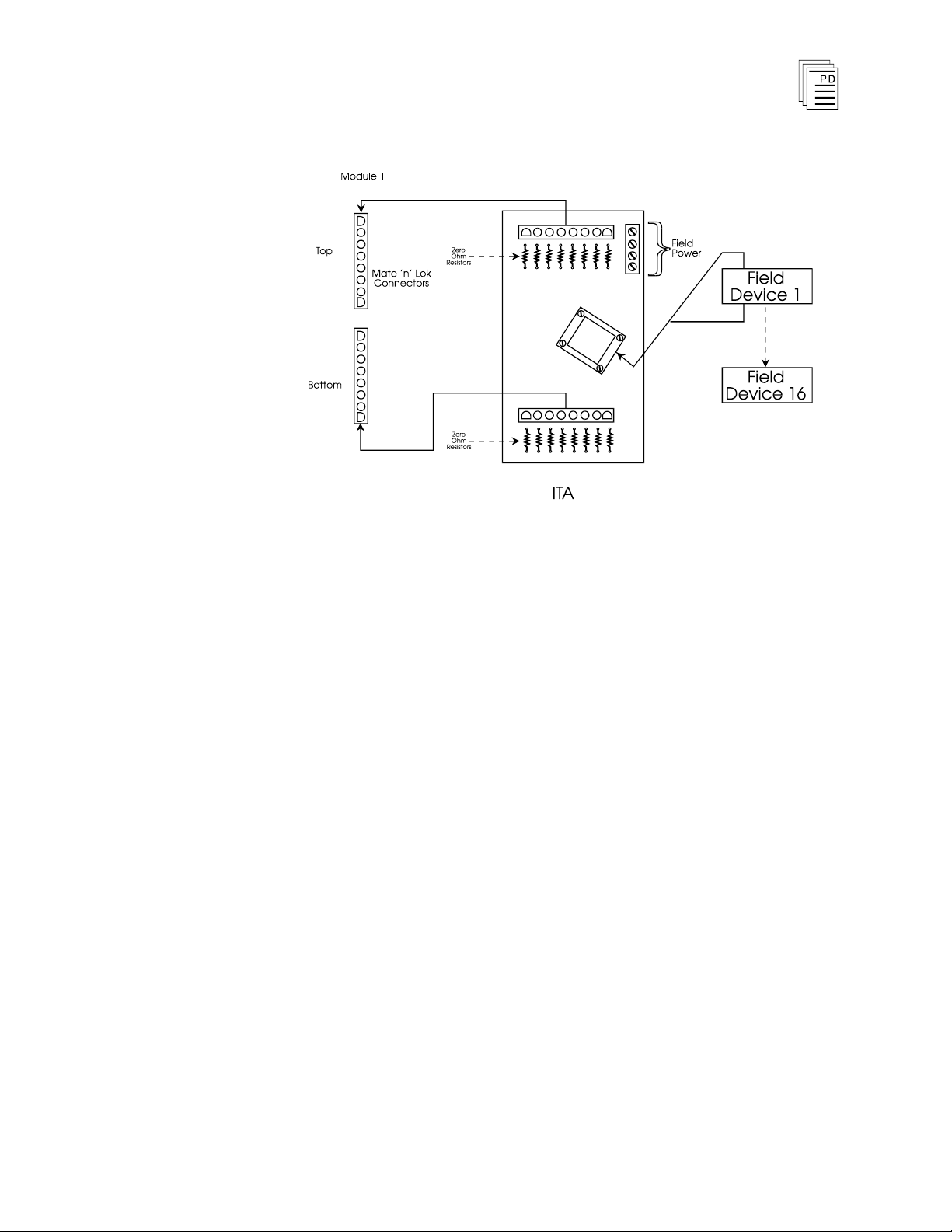
Figure B-1. Varel
Current Limiting, Field Loop, Block Diagram.
co Left Hand Single Ended, No
The modules which use the Single Ended, No Current Limiting Field
Loop ITA are listed in Table 1 of the main document.
The two 8-Way connectors are tracked to the connectors. as shown
in Tables B-1 and B-2.
PD-7901
March, 06
17
Page 18

I/O T
Connector
Pin Ident
Connector (J5) Pin
J3 S1 A
J10 Common
Return /
Feed (A)
B
J3 S2 C
J10 A D
J3 S3 E
J10 A F
J3 S4 H
J10 A
J
J3 S5 K
J10 A L
J3 S6 M
J10 A
N
J3 S7 P
J10 A
R
J3 S8
S
J10 A T
J8 S1 Y
J10 A Z
J8 S2 AA
J10 A BB
J8 S3 CC
J10 A DD
J8 S4 EE
J10 A FF
J8 S5 HH
J10 A JJ
J8 S6 KK
J10 A LL
J8 S7 MM
J10 A NN
ermination Assembly
Table B-1. Varelco Connections.
18
Industrial Control Services
Page 19

J8 S8 PP
J10 A RR
J10 GND
U, V, W, X, SS, TT
Connector
Pin Ident
Connector (J5) Pin
J3 S1 1
J10 Common
Return /
Feed (A)
2
J3 S2 3
J10 A
4
J3 S3 5
J10 A
6
J3 S4 7
J10 A
8
J3 S5 9
J10 A 10
J3 S6 11
J10 A 12
J3 S7 13
J10 A 14
J3 S8 15
J10 A 16
J8 S1 17
J10 A 18
J8 S2 19
J10 A 20
J8 S3 21
J10 A 22
J8 S4 23
J10 A 24
J8 S5 25
J10 A 26
I/O Termination Assembly
Table B-2. Screw Terminal Connections.
PD-7901
March, 06
19
Page 20

J8 S6 27
J10 A 28
J8 S7 29
J10 A 30
J8 S8 31
J10 A 32
Connector
Ident
Pin Ident
Comments
J10
A
Connect common
fe
ed/return supply.
J10
B
Connect to AGND (T7420
only) .
J10
C
Connect AREF1 &
AREF2 (T7420 only).
J10
D
No Connection.
J10
GND
Connect to Ground.
I/O T
ermination Assembly
A set of five screw terminals on the Varelco variant of the ITA provides
the facility to connect the common feed/return supply, ground spare
Varelco pins and connecting the reference voltage of analog I/O
modules (T7420) when using single ended wiring. The detailed
connections are listed in Table B-3.
Table B-3. Varelco J10 Connection Details.
The connections for the Screw Terminal Variant are the same as
above, with the exception that there are no J10 GND connections as
there are no spare connections which require grounding. A circuit
schematic is shown below.
20
Industrial Control Services
Page 21

I/O Termination Assembly
Connector
Ident
Pin Ident
Comments
J10
A
Connect common
feed/re
turn supply.
J10
B
Connect to AGND (T7420
only) .
J10
C
Connect AREF1 &
AREF2 (T7420 only).
J10
D
Cable Screen and GND.
Table B-4. Screw Terminal J10 Connection Details.
PD-7901
March, 06
21
Page 22

I/O T
ermination Assembly
Appendix C - Single Ended, Current Limiting, Field Loop With Dioded Power Protection (24V)
YTMR790112
YTMR790212
YTMR790312
The Single Ended, Current Limiting, Field Loop ITA provides the facility
to provide a method for supplying a common feed/return path to field
devices on a per module basis, as shown below. The ITA has a 2k2,
5%, 1.6W resistor in the common feed/return path. The resistor is
designed to blow open circuit if too much power is dissipated through
it.
The Single ended, Current Limiting Field Loop ITA should NOT be
used with the T7420 Analog Input Module.
The single ended signal is fed from the I/O chassis to the ITA. The ITA
provides a common dioded supply which is tracked out on the ITA to
provide each single ended signal with a current limited feed/return
supply path. The o
exceed 2.5A total if current is supplied via diodes or 16A total if
supplied via J10.
(Right Hand Varelco Connector)
(Left Hand Varelco Connector)
(Screw Terminal Connector)
verall maximum current of the ITA should not
22
Single ended I/O modules have 16 field circuits and one ITA will be
required for each module.
The connector idents are shown on the legend on the ITA.
The block diagram below shows typical connection of the module to
the field device.
Industrial Control Services
Page 23

I/O Termination Assembly
Figure C-1. Varelco Left Hand Single Ended, Current
Limiting, Field Loop With Dioded Power Protection,
Block Diagram.
The m
ITA are listed in Table 1 of the main document.
odules which use the Single Ended, Current Limiting Field Loop
The two 8-Way connectors are tracked to the connectors. as shown
in Tables C-1 and C-2.
PD-7901
March, 06
23
Page 24

I/O T
Connector
Pin Ident
Connector (J5) Pin
J3 S1 A
J10 Common
Return /
Feed (A)
B
J3 S2 C
J10 A D
J3 S3 E
J10 A F
J3 S4 H
J10 A
J
J3 S5 K
J10 A L
J3 S6 M
J10 A
N
J3 S7 P
J10 A
R
J3 S8 S
J10 A T
J8 S1 Y
J10 A Z
J8 S2 AA
J10 A BB
J8 S3 CC
J10 A DD
J8 S4 EE
J10 A FF
J8 S5 HH
J10 A JJ
J8 S6 KK
J10 A LL
J8 S7 MM
J10 A NN
ermination Assembly
Table C-1. Varelco Connections.
24
Industrial Control Services
Page 25

J8 S8 PP
J10
A RR
J10
GND
U, V, W, SS, TT
Connector
Pin Ident
Connector (J5) Pin
J3 S1 1
J10 Common
Return /
Feed (A)
2
J3 S2 3
J10 A
4
J3 S3 5
J10 A
6
J3 S4 7
J10 A
8
J3 S5 9
J10 A 10
J3 S6 11
J10 A 12
J3 S7 13
J10 A 14
J3 S8 15
J10 A 16
J8 S1 17
J10 A 18
J8 S2 19
J10 A 20
J8 S3 21
J10 A 22
J8 S4 23
J10 A 24
J8 S5 25
J10 A 26
I/O Termination Assembly
Table C-2. Screw Terminal Connections.
PD-7901
March, 06
25
Page 26

J8 S6 27
J10 A 28
J8 S7 29
J10 A 30
J8 S8 31
J10 A 32
Connector
Ident
Pin Ident
Comments
J10
A
Connect common
feed/return supply.
J10
B
Power 1 In.
J10
C
Power 2 In.
J10
D
Power 3 In.
J10
GND
Connect to ground.
I/O T
ermination Assembly
A set of five screw terminals on the Varelco variant of the ITA provides
the facility to connect the common feed/ return supply and ground
spare Varelco pins. The detailed connections are listed in Table C-3.
Table C-3. Varelco J10 Connection Details.
The connections for the Screw Terminal Variant are the same as
above, with
there are no spare connections which require grounding. A circuit
schematic is shown below.
the exception that there are no J10 GND connections as
26
Industrial Control Services
Page 27

I/O Termination Assembly
Connector
Ident
Pin Ident
Comments
J10
A
Connect common
feed/return supply.
J10
B
Power 1 in.
J10
C
Power 2 in.
J10
D
Power 3 in.
Table C-4. Screw Terminal J10 Connection Details.
PD-7901
March, 06
27
Page 28

I/O T
ermination Assembly
Appendix D - Single Ended, Analog, Current Mode
YTMR790113
YTMR790213
YTMR790313
The Single Ended, Analog, Current Mode ITA is used only in
conjunction with the T7420 Analog Input Module when it is
employing a single ended current input wiring philosophy.
The ITA provides the facility for the current conversion
required. The ITA is capable of handling 16 single ended
signals.
Single ended I/O modules have 16 field circuits and one ITA
will be required for each module.
The connector idents are shown on the legend on the ITA.
The block diagram below shows typical conne
module to the field device.
(Right Hand Varelco Connector)
(Left Hand Varelco Connector)
(Screw Ter
minal Connector)
ction of the
28
Figure D-1. Varelco Left Hand Single Ended, Analog,
Current Mode, Block Diagram.
The modules which use the Single Ended, Analog, Current
Mode ITA are listed in Table 1 of the main document.
Industrial Control Services
Page 29

I/O Termination Assembly
Connector
Pin Ident
Connector (J5) Pin
J3 S1 A
J1 S1 B
J3 S2 C
J1 S2 D
J3 S3 E
J1 S3 F
J3 S4 H
J1 S4 J
J3 S5 K
J1 S5 L
J3 S6 M
J1 S6 N
J3 S7 P
J1 S7 R
J3 S8 S
J1 S8 T
J8 S1 Y
J6 S1 Z
J8 S2 AA
J6 S2 BB
J8 S3 CC
J6 S3 DD
J8 S4 EE
J6 S4 FF
J8 S5 HH
J6 S5 JJ
J8 S6 KK
J6 S6 LL
J8 S7 MM
The two 8-Way connectors are tracked to the connectors. as
shown in Tables D-1 and D-2.
Table D-1. Varelco Connections.
PD-7901
March, 06
29
Page 30

J6 S7 NN
J8 S8 PP
J6 S8 RR
J10 GND
TT, V, W, X, SS, FT
Connector
Pin Ident
Connector (J5) Pin
J3 S1 1
J1 S1 2
J3 S2 3
J1 S2 4
J3 S3 5
J1 S3 6
J3 S4 7
J1 S4 8
J3 S5 9
J1 S5 10
J3 S6 11
J1 S6 12
J3 S7 13
J1 S7 14
J3 S8 15
J1 S8 16
J8 S1 17
J6 S1 18
J8 S2 19
J6 S2 20
J8 S3 21
J6 S3 22
J8 S4 23
J6 S4 24
J8 S5 25
J6 S5 26
I/O T
ermination Assembly
Table D-2. Screw Terminal Connections.
30
Industrial Control Services
Page 31

J8 S6 27
J6 S6 28
J8 S7 29
J6 S7 30
J8 S8 31
J6 S8 32
I/O Termination Assembly
PD-7901
March, 06
31
Page 32

I/O T
Connector
Ident
Pin Ident
Comments
J10
A
Connect to
AREF1/AREF2.
J10
B
Connect AGND.
J10
C
Connect to Field Power
Supply Return.
J10
D
No Connection.
J10
GND
No Connection.
ermination Assembly
A set of five screw terminals on the Varelco variant of the ITA provides
the facility to connect the negative supply, AGND, AREF and to ground
the spare Varelco pins.. The detailed connections are listed in Table
D-3.
Table D-3. Varelco J10 Connection Details.
32
Industrial Control Services
Page 33

I/O Termination Assembly
Connector
Ident
Pin Ident
Comments
J10
A
Connect to
AREF1/AREF2.
J10
B
Connect AGND.
J10
C
Connect to Field Power
Supply Return.
J10
D
Cable Screen and GND.
Table D-4. Screw Terminal J10 Connection Details.
PD-7901
March, 06
33
Page 34

I/O T
ermination Assembly
Appendix E - Single Ended, External Current Limiting
YTMR790114
YTMR790214
YTMR790314
The Single Ended, External Current Limiting I
fusing each path of the field loop when using single ended modules.
The ITA is capable of handling 16 single ended signals. Each field
circuit has a maximum current rating of 2A.
Single ended I/O modules have 16 field circuits and one ITA will be
required for each module.
The connector idents are shown on the legend on the ITA.
The block diagram below shows typical connection of the module to
the field device.
(Right Hand Varelco Connector)
(Left Hand Varelco Connector)
(Screw Terminal Connector)
TA provides the facility for
34
Figure E-1. Varelco Left Hand Single Ended,
Ext
ernal Current Limiting, Block Diagram.
The modules which use the Single Ended, External Current
Limiting ITA are listed in Table 1 of the main document.
Industrial Control Services
Page 35

I/O Termination Assembly
Connector
Pin Ident
Connector (J5) Pin
J3 S1 A
J1 S1 B
J3 S2 C
J1 S2 D
J3 S3 E
J1 S3 F
J3 S4 H
J1 S4 J
J3 S5 K
J1 S5 L
J3 S6 M
J1 S6 N
J3 S7 P
J1 S7 R
J3 S8 S
J1 S8 T
J9 S1 Y
J7 S1 Z
J9 S2 AA
J7 S2 BB
J9 S3 CC
J7 S3 DD
J9 S4 EE
J7 S4 FF
J9 S5 HH
J7 S5 JJ
J9 S6 KK
J7 S6 LL
J9 S7 MM
The four 8-Way connectors are tracked to the connectors. as shown
in Tables E-1 and E-2.
Table E-1. Varelco Connections.
PD-7901
March, 06
35
Page 36

J7 S7 NN
J9 S8 PP
J7 S8 RR
J10 GND
U, V, W, X, SS, TT
I/O T
ermination Assembly
36
Industrial Control Services
Page 37

I/O Termination Assembly
Connector
Pin Ident
Connector (J5) Pin
J3 S1 1
J1 S1 2
J3 S2 3
J1 S2 4
J3 S3 5
J1 S3 6
J3 S4 7
J1 S4 8
J3 S5 9
J1 S5 10
J3 S6 11
J1 S6 12
J3 S7 13
J1 S7 14
J3 S8 15
J1 S8 16
J8 S1 17
J6 S1 18
J8 S2 19
J6 S2 20
J8 S3 21
J6 S3 22
J8 S4 23
J6 S4 24
J8 S5 25
J6 S5 26
J8 S6 27
J6 S6 28
J8 S7 29
J6 S7 30
J8 S8 31
Table E-2. Screw Terminal Connections.
PD-7901
March, 06
37
Page 38

J6 S8 32
I/O T
ermination Assembly
38
Industrial Control Services
Page 39

I/O Termination Assembly
Connector
Ident
Pin Ident
Comments
J10
A
Connect AREF1 and
AREF2.
J10
B
Connect AGND (T7420).
J10
C
Connect Fused Common
Return (T7420).
J10
D
No Connection.
J10
GND
Connect to ground.
A set of five screw terminals on the Varelco variant of the ITA provides
the facility to connect to ground the spare Varelco pins. This ITA can
be used with T7420 when using differential voltage input wiring. The
detailed connections are listed in Table E-3.
Table E-3. Varelco J10 Connection Details.
PD-7901
March, 06
39
Page 40

I/O T
Connector
Ident
Pin Ident
Comments
J10
A
Connect AREF1 and
AREF2.
J10
B
AGND (T7420).
J10
C
Connect Fused Common
Return
J10
D
Cable Screen and GND.
ermination Assembly
Table E-4. Screw Terminal J10 Connection Details.
40
Industrial Control Services
Page 41

I/O Termination Assembly
Appendix F - Differential, Analog Current Mode
YTMR790115
YTMR790215
YTMR790315
The Differential, Analog Current Mode, ITA provides the facility to
connect sixteen differential fiel
Differential, Field Loop, ITA is capable of feeding two modules, as
shown in the block diagrams below:
(Right Hand Varelco Connector)
(Left Hand Varelco Connector)
(Screw Terminal Connector)
d circuits to the I/O modules. One
PD-7901
March, 06
Figure F-1. Varelco Left Hand Differential, Analog
Current Mode, Block Diagram.
41
Page 42

I/O T
ermination Assembly
This ITA is used with the T7420 modules when in Differential Current
Mode. The modules function in a manner such that the field devices
require a 250 ohm resistor across its path, as illustrated below:
The connector idents are shown on the legend on
the ITA.
42
Industrial Control Services
Page 43

I/O Termination Assembly
Connector
Pin Ident
Connector (J5) Pin
J2 S1 C
J2 S2 D
J2 S3 H
J2 S4 J
J2 S5 M
J2 S6 N
J2 S7 S
J2 S8 T
J4 S1 A
J4 S2 B
J4 S3 E
J4 S4 F
J4 S5 K
J4 S6 L
J4 S7 P
J4 S8 R
J7 S1 AA
J7 S2 BB
J7 S3 EE
J7 S4 FF
J7 S5 KK
J7 S6 LL
J7 S7 PP
J7 S8 RR
J9 S1 Y
J9 S2 Z
J9 S3 CC
J9 S4 DD
J9 S5 HH
The four 8-Way connectors are tracked to the connectors. as shown
in Tables F-1 and F-2.
Table F-1. Varelco Connections.
PD-7901
March, 06
43
Page 44

J9 S6 JJ
J9 S7 MM
J9 S8 NN
J10 GND
U, V, W, X, SS, TT
Connector
Pin Ident
Connector (J5) Pin
J2 S1 3
J2 S2 4
J2 S3 7
J2 S4 8
J2 S5 11
J2 S6 12
J2 S7 15
J2 S8 16
J4 S1 1
J4 S2 2
J4 S3 5
J4 S4 6
J4 S5 9
J4 S6 10
J4 S7 13
J4 S8 14
J7 S1 19
J7 S2 20
J7 S3 23
J7 S4 24
J7 S5 27
J7 S6 28
J7 S7 31
J7 S8 32
J9 S1 17
J9 S2 18
I/O T
ermination Assembly
Table F-2. Screw Terminal Connections.
44
Industrial Control Services
Page 45

J9 S3 21
J9 S4 22
J9 S5 25
J9 S6 26
J9 S7 29
J9 S8 30
I/O Termination Assembly
PD-7901
March, 06
45
Page 46

I/O T
Connector
Ident
Pin Ident
Comments
J10
A
Connect to module
AREF1 & AREF2.
J10
B
Connect to AGND (T7420
only).
J10
C
Link to Field Supply
Return.
J10
D
No Connection.
J10
GND
No Connection.
ermination Assembly
A set of five screw terminals on the Varelco variant of the ITA provides
the facility to ground the spare Varelco pins and fo
analog voltage to be connected to the I/O module. The detailed
connections are listed in Table F-3.
r the reference
Table F-3. Varelco J10 Connection Details.
46
Industrial Control Services
Page 47

I/O Termination Assembly
Connector
Ident
Pin Ident
Comments
J10
A
Connect to AREF1 & 2.
J10
B
Connect to AGND.
J10
C
Connect to Field Supply
Return.
J10
D
No Connection.
A set of four screw terminals on the Screw Terminal variant of the ITA
provides the facility for the reference voltage to be passed to the
T7420 Analog
the detailed connections are listed in Table F-4.
Input Module. A circuit schematic is shown below and
Table F-4. Screw Terminal J10 Connection Details.
PD-7901
March, 06
47
Page 48

I/O T
ermination Assembly
Appendix G - Differential, Field Loop With Dioded Power Protection
YTMR790116
YTMR790216
YTMR790316
The Differential, Field Loop with Dioded Power Protection,
ITA provides the facility to connect sixteen differential field
circuits to the I/O modules. One Differential, Field Loop, ITA
is capable of feeding two modules, as shown in the block
diagrams below:
(Right Hand Varelco Connector)
(Left Hand Varelco Connector)
(Screw Terminal Connec
tor)
48
Figure G-1. Varelco Left Hand Differential, Field
Loop with Dioded Power Protection, Block Diagram.
Industrial Control Services
Page 49

I/O Termination Assembly
The modules which use the Differential Field Loop with Dioded Power
Protection ITA are listed in Table 1 of the main document
. These
modules function in a manner such that the field devices do not
require a common feed or return, as illustrated below:
The connector idents are shown on the legend on the ITA.
PD-7901
March, 06
49
Page 50

I/O T
Connector
Pin Ident
Connector (J5) Pin
J2 S1 C
J2 S2 D
J2 S3 H
J2 S4 J
J2 S5 M
J2 S6 N
J2 S7 S
J2 S8 T
J4 S1 A
J4 S2 B
J4 S3 E
J4 S4 F
J4 S5 K
J4 S6 L
J4 S7 P
J4 S8 R
J7 S1 AA
J7 S2 BB
J7 S3 EE
J7 S4 FF
J7 S5 KK
J7 S6 LL
J7 S7 PP
J7 S8 RR
J9 S1 Y
J9 S2 Z
J9 S3 CC
J9 S4 DD
J9 S5 HH
ermination Assembly
The four 8-Way connectors are tracked to the connectors. as shown
in Tables G-1 and G-2.
Table G-1. Varelco Connections.
50
Industrial Control Services
Page 51

J9 S6 JJ
J9 S7 MM
J9 S8 NN
J10 GND
U, V, W, X, SS, TT
Connector
Pin Ident
Connector (J5) Pin
J2 S1 3
J2 S2 4
J2 S3 7
J2 S4 8
J2 S5 11
J2 S6 12
J2 S7 15
J2 S8 16
J4 S1 1
J4 S2 2
J4 S3 5
J4 S4 6
J4 S5 9
J4 S6 10
J4 S7 13
J4 S8 14
J7 S1 19
J7 S2 20
J7 S3 23
J7 S4 24
J7 S5 27
J7 S6 28
J7 S7 31
J7 S8 32
J9 S1 17
J9 S2 18
I/O Termination Assembly
Table G-2. Screw Terminal Connections.
PD-7901
March, 06
51
Page 52

J9 S3 21
J9 S4 22
J9 S5 25
J9 S6 26
J9 S7 29
J9 S8 30
I/O T
ermination Assembly
52
Industrial Control Services
Page 53

I/O Termination Assembly
Connector
Ident
Pin Ident
Comments
J10
A
Diode Protected Power
Out.
J10
B
Power 1 In
J10
C
Power 2 In
J10
D
Power 3 In
J10
GND
Connect to ground
A set of five screw terminals on the Varelco variant of the ITA provides
the facility to ground the spare Varelco pins. The detailed connections
are listed in Table G-3.
Table G-3. Varelco J10 Connection Details.
PD-7901
March, 06
53
Page 54

I/O T
Connector
Ident
Pin Ident
Comments
J10
A
Diode Protected Power
Out.
J10
B
Power 1 In.
J10
C
Power 2 In.
J10
D
Power 3 In
ermination Assembly
A set of four screw terminals on the Screw Terminal variant of the ITA
provi
des the facility for the reference voltage to be passed to the
T7420 Analog Input Module. A circuit schematic is shown below and
the detailed connections are listed in Table G-4.
The maximum protected current is 2.5A total, with any configuration of
redundant supply.
Table G-4. Screw Terminal J10 Connection Details.
54
Industrial Control Services
Page 55

I/O Termination Assembly
Appendix H - Single Ended, No Current
Li
miting, Field Loop With Dioded Power
Protection
YTMR790117
YTMR790217
YTMR790317
The Single Ended, No Current Limiting, Field Loop With Dioded Power
Protection ITA provides a method for supplying a common feed/return
path to field devices on a per module basis, as shown below:
(Right Hand Varelco Connector)
(Left Hand Varelco Connector)
(Screw Terminal Connector)
PD-7901
March, 06
The single ended signal is fed from the I/O chassis to the ITA. The ITA
provides a common supply which is tracked out on the
each single ended signal with a feed/return supply path. The overall
maximum current of the ITA should not exceed 2.5A in any redundant
power configuration where diodes are used or 16A total where power
is supplied to field loops via J10 Pin A (diodes not used).
Single ended I/O modules have 16 field circuits and one ITA will be
required for each module.
The connector idents are shown on the legend on the ITA.
The block diagrams below show typical connection of the module to
the field device
.
ITA to provide
55
Page 56

I/O T
ermination Assembly
Figure H-1. Varelco Left Hand Single Ended, No
Current Limiting, Field Loop With Dioded Power
Protection, Block Diagram.
The modules which use the Single Ended, No Current Limiting Field
Loop With Dioded Power Protection ITA are listed in Table 1 of the
main document.
The two 8-Way connectors are tracked to the connectors. as shown
in Tables H-1 and H-2.
56
Industrial Control Services
Page 57

I/O Termination Assembly
Connector
Pin Ident
Connector (J5) Pin
J3 S1 A
J10 Common
Return /
Feed (A)
B
J3 S2 C
J10 A D
J3 S3 E
J10 A F
J3 S4 H
J10 A
J
J3 S5 K
J10 A L
J3 S6 M
J10 A
N
J3 S7 P
J10 A
R
J3 S8 S
J10 A T
J8 S1 Y
J11 A Z
J8 S2 AA
J11 A BB
J8 S3 CC
J11 A DD
J8 S4 EE
J11 A FF
J8 S5 HH
J11 A JJ
J8 S6 KK
J11 A LL
J8 S7 MM
J11 A NN
Table H-1. Varelco Connections.
PD-7901
March, 06
57
Page 58

J8 S8 PP
J11 A RR
J10 GND
U, V, W, X, SS, TT
Connector
Pin Ident
Connector (J5) Pin
J3 S1 1
J10 Common
Return /
Feed (A)
2
J3 S2 3
J10 A
4
J3 S3 5
J10 A
6
J3 S4 7
J10 A
8
J3 S5 9
J10 A 10
J3 S6 11
J10 A
12
J3 S7 13
J10 A 14
J3 S8 15
J10 A 16
J8 S1 17
J11 A 18
J8 S2 19
J11 A 20
J8 S3 21
J11 A 22
J8 S4 23
J11 A 24
J8 S5 25
J11 A 26
I/O T
ermination Assembly
Table H-2. Screw Terminal Connections.
58
Industrial Control Services
Page 59

J8 S6 27
J11 A 28
J8 S7 29
J11 A 30
J8 S8 31
J11 A 32
Connector
Ident
Pin Ident
Comments
J10
A
Power In/Out
J10
B
Power 1 In
J10
C
Power 2 In
J10
D
Power 3 In
J10
GND
Connect to ground.
I/O Termination Assembly
A set of five screw terminals on the Varelco variant of the ITA provides
the facility to connect the common feed/ return supply and ground
spare Varelco pins. The detailed connections are listed in Table H-3.
Table H-3. Varelco J10 Connection Details.
The connections for the Screw Terminal Variant are the same as
above, with the exception that there are no J10 GND connections as
there are no spare connections which require grounding. A circuit
schematic is shown below.
PD-7901
March, 06
59
Page 60

I/O T
Connector
Ident
Pin Ident
Comments
J10
A
Power In/Out.
J10
B
Power 1 in .
J10
C
Power 2 in.
J10
D
Power 3 in.
ermination Assembly
Table H-4. Screw Terminal J10 Connection Details.
60
Industrial Control Services
 Loading...