


ICS Regent+Plus
®
PD-7018
AC Isolated Digital Output Module
110 VAC
(T7454)
Issue 1,
The AC isolated digital output module provides control of
eight isolated user output loads. One type of module is
available to interface to outputs powered from is
VAC field power supplies. Each module's triplicated I/O
Safetybus interface ensures that no Regent system failure can
incorrectly apply power to an output, and that no failure in
the module can affect the operation of the Regent system or
other I/O modules in the system.
olated 110
March, 06
Module
Features
·
Eight isolated 110 VAC output circuits.
·
Hot-replaceable.
·
Automatic self-testing of triplicated I/O Safetybus circuits
many simplex logic circuits.
·
2 amp output circuits.
·
Zero-cross load switching.
·
Individual front panel indicators on each module show active
and fault, shutdown, blown fuse, and output on/off status (logic
side).
·
2500 volt minimum electrical isolation between field and logic
circuits.
·
TÜV certified, Risk Class 5, non-interfering.
Operation
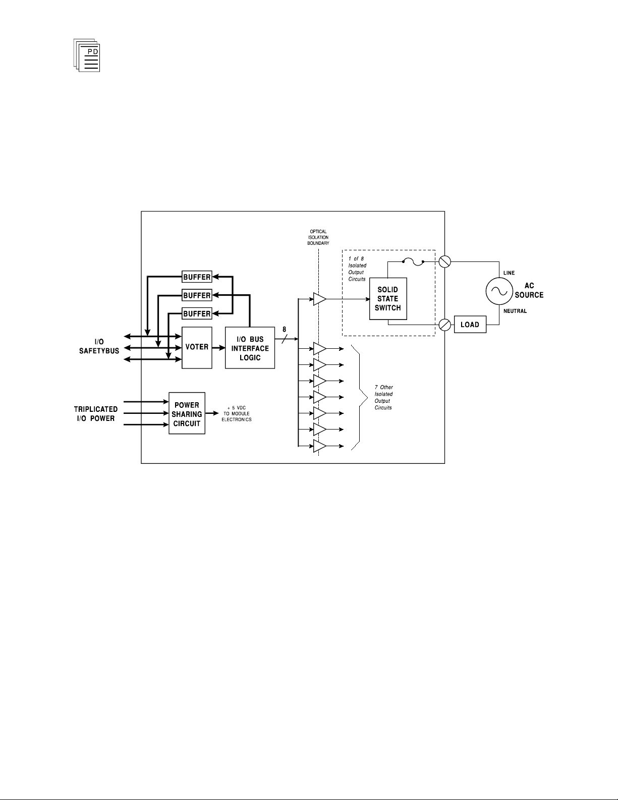
A block diagram of a typical 110 VAC isolated digital output
module is shown in Figure 1.
and
Industrial Control Services
1
AC Isolated Digital Output Module
The processor modules send triplicated write data commands
to the output module over the I/O Safetybus. The processors’
addressing data and data write commands are voted by the
module (preventing I/O Safetybus failures upstream from the
module from affecting module operation). The voted result is
then passed to the I/O bus interface logic.
(T7454)
2
Fig
ure 1. Block Diagram of 110 VAC Isolated Digital Output Module.
The voted output data from the I/O bus interface logic is then
used to drive the output circuits. Zero crossing turn-on
TRIAC drivers are used to convert the logic level output drive
signals to switch 110 VAC power to load devices.
When the output is logically turned on, the field device is
energized, and when the output is logically turned off, the
field device is de-energized.
Optical isolation between the module’s logic and fi
provides logic-to-field isolation
— protecting the output
module from field signal over voltages, transients, and other
electrical disturbances. It also provides a safety barrier
between the primary field voltages and user accessible
circuits. Additionally each output is isolated from the other
Industrial Control Services
eld circuits

(T7454)
outputs, to operate load devices powered from isolated field
power supplies.
Each output is individually fused to protect the circuits from
short circuit conditions in output wiring and field devices.
AC Isolated Digital Output Module
Testing and Diagnostics
Each module’s voter circuits are periodically tested by the
processor modules. Discrepant data are sent through one of
three legs of the I/O Safetybus to determine whether the
module’s voter is able to outvote the incorrect data. A failure
to return the correct majority-voted result to the processors
produces an I/O module error indication at the processor
modules and a module fault indication at the I/O module.
Each type of module has a unique identification code that is
read by t
which type of module is installed in each I/O chassis slot and
how to address that module and its points specifically. If a
module is removed, or is replaced with a module of a different
type, the processor modules will indicate an I/O module error.
Loopback logic tests periodically write data to the module and
then read it back to determine whether the module’s I/O bus
interface logic is functioning correctly.
Fuses are continually checked for continuity.
the minimum load (see Specifications, page 12) must be
connected to each output in order to detect a blown fuse.
he controller. This code lets the controller know
Field power and
PD-7018
Mar-06
Front Panel Indicators
The 110 VAC isolated digital output module is shown in
Figure 2. The front panel contains the active and fault status
indicators, shutdown indicator, and output status and blown
fuse indicators for each output circuit.
Active and Fault Status Indicators
These green and red LEDs indicate the overall health
module. During normal operation, the green ACTIVE
indicator flashes at the controller’s scan rate. If a module
fault is detected the red FAULT indicator turns on and the
green indicator turns off.
3
of the

Note:
AC Isolated Digital Output Module
(T7454)
Shutdown Indicator
Upon loss of communications with the controller, output
modules enter either a shutdown or hold fault mode. If the I/O
assembly is set to shutdown, the red SHUTDOWN indicator
will turn on when communications with the controller are lost.
If the I/O assembly is set to hold, the SHUTDOW
will always be off (see page 7, Fault Mode Jumper).
N indicator
When the module is installed in the I/O chassis or when logic
power (from the I/O power supply modules) is first applied to
the module, it will be in the shutdown mode until the first
output scan, regardless of the fault mode jumper settings.
Also, removing two I/O transceiver modules, two I/O power
supply modules, or two power legs will cause the module to be
in the shutdown mode.
Output Status Indicators
The output status indicators are yellow LEDs, located on the
logic side of the output. There are 8 output status indicators
— one for each output. These indicators are lit when the
output TRIAC is energized to turn on the load.
Blown Fuse Indicators
The red BLOWN FUSE indicators turn on when the
associated output’s internal fuse opens. A blown fuse will also
cause the module’s FAULT indicator to turn on.
The module must be connected to a load and field power must
be present to detect a blown fuse. Refer to Maintenance, page
11
, for fuse replacement instructions.
4
Industrial Control Services
 Loading...