

Page 1
ICS Regent+Plus
®
PD-7017
Relay Output Modules
Low Power and High Power
(T7446L and T7446H)
Issue 1,
Relay output modules provide control of eight user output
loads. Two types of relay output modules are available
providing dry contact relay clos
variety of AC and DC voltages to field loads. Each module's
triplicated I/O Safetybus interface ensures that no Regent
system failure can incorrectly apply power to an output and
that no failure in the module can affect the operation of the
Regent system or other I/O modules in the system.
ure outputs for switching a
March, 06
Features
·
Eight isolated, dry contact relay outputs: four Form-C, and four
form-A or Form-B selectable.
·
Hot replaceable.
·
Automatic self-testing of triplicated I/O Safetybus circuits and
many simplex logic circuits.
·
High power modules (T7446H) operate up to 250 VAC/125
VDC switching loads rated at 500 VA or 100 Watts.
·
Low power modules (T7446L) operate up to 125 VAC/VDC
switching loads rated at 60 VA or 30 Watts.
·
Individual front panel indicators on each module show active
and fault status, shutdo
side).
·
TÜV certified, Risk Class 5, non-interfering.
wn state, and output status (logic
Industrial Control Services
1
Page 2
Relay Output Modules
(T7446L, H)
Module Operation
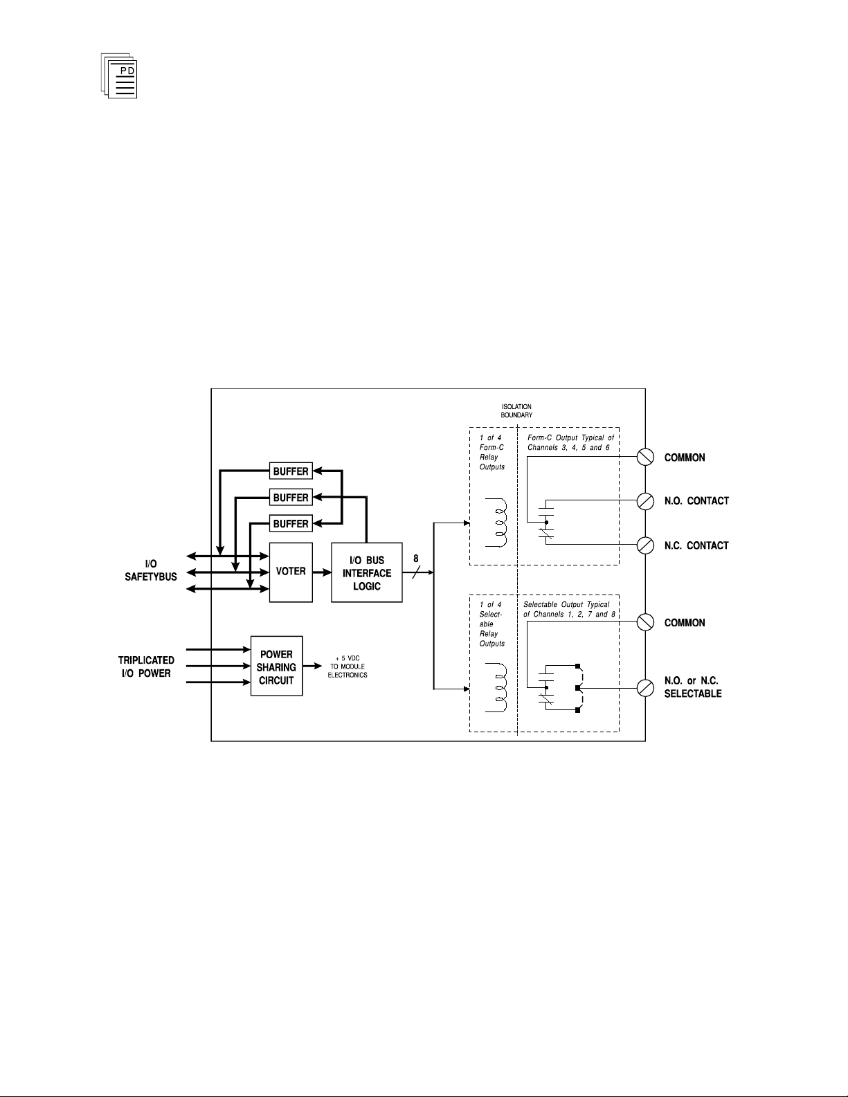
A block diagram of a typical relay output module is shown in
Figure 1.
The processor modules send triplicated write data commands
to the output module over the I/O Safetybus. The processors’
addressing data and data write commands are voted by the
module (preventing I/O Safetybus failures upstream from the
module from affecting module operatio
then passed to the I/O bus interface logic.
n). The voted result is
2
Figure 1. Block Diagram of a Relay Output Module.
The voted output data from the I/O bus interface logic is then
used to drive the output circuits. Logic output drive signals
energize the coils of relays mounted on the printed circuit
board. Relay contacts provide dry-contact switching of load
devices.
When the output is logically turned on, the relay coil is
energized (closing the N.O.
contact), and when the output is
Industrial Control Services
Page 3

(T7446L, H)
logically turned off, the relay coil is de-energized (closing the
N.C. contact).
The relay provides logic-to-field isolation between the
module’s logic and field circuits — protecting the output
module from field signal over voltages, transients, and other
electrical disturbances.
Both types of relay output module use UL 508 approved
relays.
Relay Output Modules
Testing and Diagnostics
Each module’s voter circuits are periodically tested by the
processor modules. Discrepant data are sent throug
three legs of the I/O Safetybus to determine whether the
module’s voter is able to outvote the incorrect data. A failure
to return the correct majority-voted result to the processors
produces an I/O module error indication at the processor
modules and a module fault indication at the I/O module.
Each type of module has a unique identification code that is
read by the controller. This code lets the controller know
which type of module is installed in each I/O chassis slot and
how to address that m
module is removed, or is replaced with a module of a different
type, the processor modules will indicate an I/O module error.
Loopback logic tests periodically write data to the module and
then read it back to determine whether the module’s I/O bus
interface logic is functioning correctly.
odule and its points specifically. If a
Front Panel Indicators
h one of
PD-7017
Mar-06
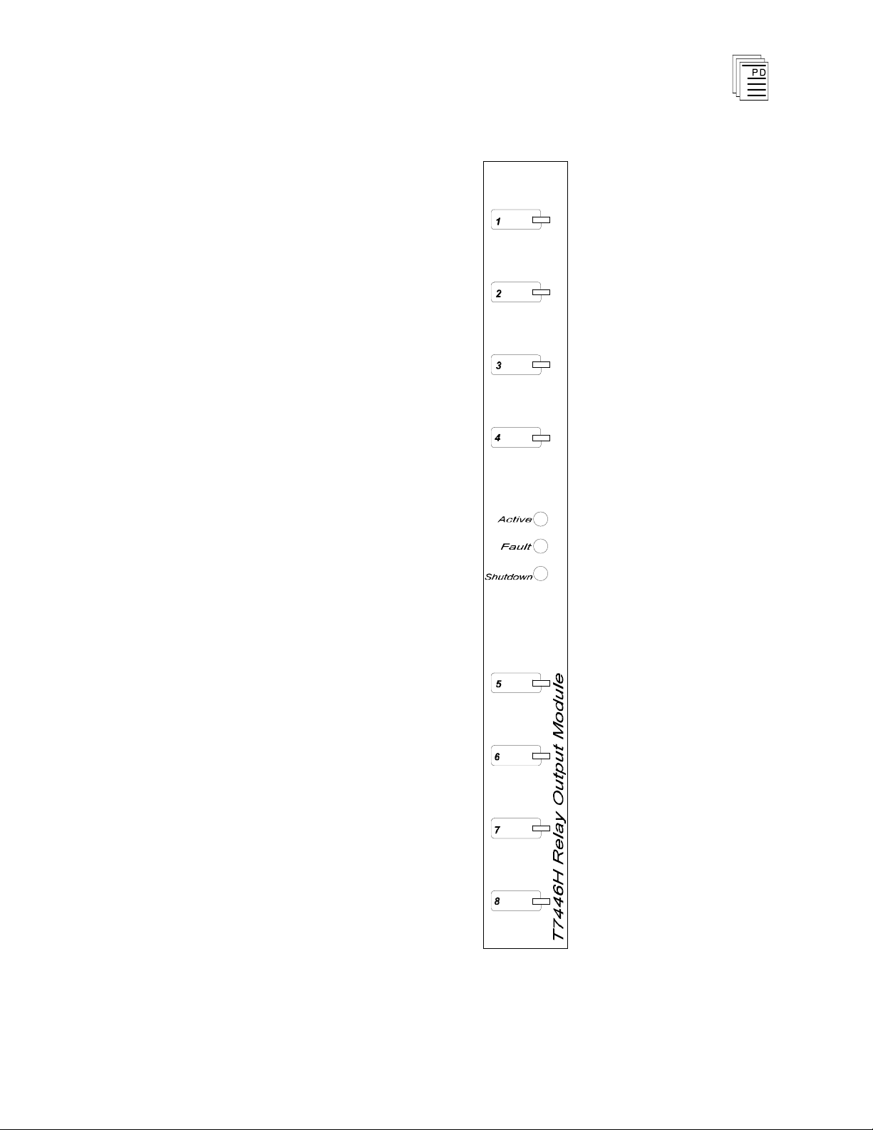
The relay output module is shown in Figure 2. The front
panel contains active and fault status indicators, a shutdown
indicator, and output status indicators for each output circuit.
Active and Fault Status Indicators
These green and red LEDs indicate the overall health of the
module. During normal operation the green ACTIVE
indicator flashes at the controller's scan rate. If a module
fault is detected the red FAULT indicator turns on and the
green indicator turns off.
3
Page 4

Note:
Relay Output Modules
(T7446L, H)
Shutdown Indicator
Upon loss of communications with the controller, output
modules enter either a shutdown or hold fault mode. If the I/O
assembly is set to shutdown, the red SHUTDOWN indicator
will turn on when communications with the controller are lost.
If the I/O assembly is set to hold, the SHUTDOWN indicator
will always be off (see page 11, Fault Mode Jumper).
When the module is installed in the I/O chassis or when logic
power (from the I/O power supply modules) is first applied to
the module, it will be in the shutdown mode until the first
output scan, regardless of the fault mode jumper settings.
Also, removing two I/O transceiver mo
dules, two I/O power
supply modules, or two power legs will cause the module to be
in the shutdown mode.
Output Status Indicators
The output status indicators are yellow LEDs located on the
logic-side (coil) of the relay output. There are eight output
status indicators
— one for each output. These indicators are
lit when the output relay coil is energized, closing the
normally open contact.
4
Industrial Control Services
Page 5
(T7446L, H)
Relay Output Modules
PD-7017
Mar-06
Figure 2. Relay Output Module.
5
Page 6
Relay Output Modules
(T7446L, H)
Application
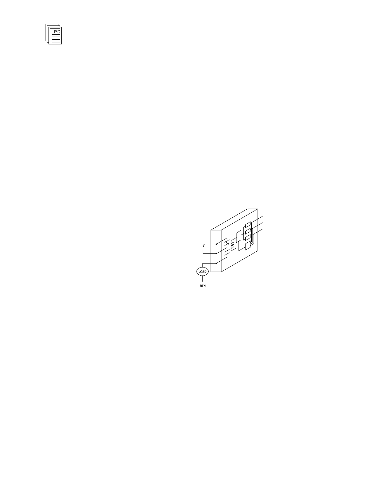
Simplex Configuration
Relay o
critical output devices. These non-critical devices typically
include status alarms or other field devices that are not used
for primary safety shutdown purposes. Although much of the
circuitry on the relay output module is automatically tested,
some logic circuits and the field-side output switch are simplex
and non-tested. This simplex configuration is illustrated in
Figure 3. For safety-critical outputs requiring fail-safe
fault tolerant output configurations, Guarded digital output
modules should be used.
utput modules provide a suitable interface to non
-
or
6
Figure 3. Simplex Relay Output Configuration.
Field Wiring
For field wiring details, refer to PD-7901 - I/O Termination
Assembly (ITA).
Industrial Control Services
Page 7

(T7446L, H)
Jumper
Form
Description
E110
NO1
Selects normally open for relay 1
E111
NC1
Selects normally closed for relay 1
E120
NO2
Selects normally open for relay 2
E121
NC2
Selects normally closed for relay 2
E170
NO7
Selects normally open for relay 7
E171
NC7
Selects normally closed for relay 7
E180
NO8
Selects normally open for relay 8
E181
NC8
Selects normally
closed for relay 8
Relay Output Modules
Relay Operation
The relays used on the T7446L contain SPDT contacts. For
the Form-A or Form-B selectable outputs, a jumper in the
module is used to select Form-A (N.O.) or Form-B (N.C.)
action.
The relays used on the T7446H contain t
(one normally closed and one normally open). Jumpers within
the module are also used to select the relay form. On the
Form-C output, there is no guarantee for make-before-break
or break-before-make.
Output Form Selection
Two sets of jumper posts are used to select the output form for
the selectable relays. The jumper locations are shown in
Figure 4. The jumper post designations are shown in Table 1.
Only one jumper shunt can be installed for each relay. The
modules are shipped with the jumpers positioned for normally
open contact outputs.
wo SPST contacts
Table 1. Jumper Designations.
PD-7017
Mar-06
7
Page 8

Relay Output Modules
(T7446L, H)
8
Figure 4. Jumper Locations.
Operating Envelope
Figure 5 shows the voltage and current operating envelopes
for the T7446L and T7446H. The T7446L relays are initially
gold clad and have an initial resistance of 50 mOhm
maximum. However, operation at high voltages and currents
will remove the gold and the closed resistance will increase
substantially. This increased resistance reduces its ability to
subsequently s
witch very low power loads.
Industrial Control Services
Page 9

(T7446L, H)
Relay Output Modules
As with any relay, operating at higher voltages and currents
will result in decreased relay life. Figure 6 shows the voltage
and current versus service life for the relays.
PD-7017
Mar-06
Figure 5. Voltage and Current Operating Envelopes.
9
Page 10

10
100
1000
10000
100000
0
0.4 0.8 1.2 1.6
2
2.4
10
100
1000
10000
100000
0
0.4 0.8 1.2 1.6
2
2.4
Relay Output Modules
(T7446L, H)
Figure 6. Voltage and Current vs. Service Life.
Relay Protection
Each relay circuit must be fused externally to protect the
relay and the load. Modules are also fused internally with
factory-replaceable fuses to protect the I/O assembly and the
module’s printed circuit board.
If an inductive load is connected, a suitable snubber must be
externally provided.
10
Industrial Control Services
Page 11

(T7446L, H)
Module
Upper
Connector
Lower
Connector
T7446H
T7446L
17 2
Relay Output Modules
Fault Mode Jumper
The fault mode jumper is located behind the ID switch cover
in the lower left-hand corner of each I/O chassis. The position
of the fault mode jumper determines the module's response to
system level faults. The fault mode jumper’s position will
cause all output m
(turn off all outputs) or to hold (hold the last state) after a
system level failure occurs. An example of a system level
failure is the failure of two processor modules.
Keying
The I/O chassis can be physically keyed to prevent accidental
damage caused by inserting a module into a slot wired for a
different module type. Figure 7 illustrates how the slot keys
are installed on the I/O chassis slot field wiring connectors.
The slot key pos
Table 2. Both versions of the relay output module use the
same slot key positions.
odules in the I/O chassis to either shutdown
itions for the relay output module are listed in
Table 2. Slot Key Positions.
PD-7017
Mar-06
11
Page 12

Relay Output Modules
(T7446L, H)
12
Figure 7. Installing Slot Keys.
Configuration
Each output module is configured using the
W
INTERPRET
I/O
Configuration Editor. In the editor you will perform the three
steps described below to co
nfigure the output module.
Industrial Control Services
Page 13

(T7446L, H)
Relay Output Modules
1) Set the Module Type:
Position the cursor on the module slot you wish to define.
Choose Set Module Type from the Edit Menu and select
the relay output module from the list.
2) Edit the Module Definition:
Choose Edit Module Definition from the Edit Menu. A
dialog box will open where you can define the output point
definitions.
Figure 8. Relay Output Module Definition.
3) Edit each point:
Choose Edit from the Module Definition dialog box to
define a name and description for each output point. In
the Digital Output Point dialog, enter names and values
for the configuration fields as described below.
Figure 9. Defining a Digital Output Point.
PD-7017
Mar-06
13
Page 14

Relay Output Modules
(T7446L, H)
Name
Also called the tag name, this is the name used in the
application program to reference the output point. The name
can be up to 12 characters long.
Description
This 40-character field provides a place to describe the output
point definition. The description is used to help document
your system (it does
Comm Protect
not affect application program operation).
Marking the Comm Protect check box protects the point from
changes by communications functions such as data write,
forcing, and load initial value when Comm Protect is enabled.
Initial Value
The initial value for the output is loaded to the Regent when
you load the I/O configuration and also when you load the
application program that controls the output.
Final Value
The final value for the output is loaded to the Regent when
the application program th
at controls the output is deleted.
Unless special circumstances exist, you should always enter
zero, so that the output is turned off when you delete the
application program that controls it.
Output Module Definition
In addition to configuring output point definitions, you can
configure an output module definition to represent the
combined state of all eight output points. The module
definition represents the eight output point definitions as
signed, 16-bit integers. In this format, the eight outputs are
the least significant bits with output point 1 as the LSB. The
eight most significant bits are always zero.
Programming
Outputs are controlled by writing application programs that
solve for output values. For example, placing an output tag
name on a coil in ladder logic will cause the output to turn on
when there is power flow to the coil in the ladder logic rung.
You can also reference the logic state of the output in your
14
Industrial Control Services
Page 15

(T7446L, H)
control logic by using a contact element (or similar element)
with the output point name.
Relay Output Modules
Maintenance
No periodic maintenance or calibration is required for this
module. If a module is to be replaced, verify the replacement
module’s relay form configuration matches the original relay
output module.
Fuses for each output are located inside the module.
fuses are for protection of the I/O chassis connectors and
module circuit board only, and are not field-replaceable
Should an internal fuse blow, it indicates that the module is
being used for output loads in excess of the safe r
module and the I/O chassis.
Modules with blown fuses should be returned to ICS for repair
or replacement.
Safety Considerations
The relay output modules are TÜV certified as non
interfering, and can be used in a safety system for simplex
non-safety critical outputs. For safety critical outputs,
guarded output modules should be used (model T7481, T7484,
T7485 or T7488 are recommended).
These
.
ating of the
-
PD-7017
Mar-06
15
Page 16

Safetybus Power
1.0 load units
Number of Outputs
Eight isolated c
ircuits (four
Form-C contacts, four
selectable N.O. or N.C.
contacts)
T7446L
T7446H
Voltage Range
0.1 to 125 VAC/DC
5 to 250 VAC
5 to 125 VDC
Load Current
2.0 amps
2.0 amps
Minimum Load
0.1 VDC/10 mA
5 VDC/10 mA
Surge Current
20 amps, 16 msec
20 amps, 16 msec
Over Voltage
Protection
750 VAC, 1 minute
1000 VAC, 1
minute
Rated Load
resistive
110 VAC, 0.3 amps
24 VDC, 1 amp
250 VAC, 2 amps
50 VDC, 2 amps
inductive
110 VAC, 0.2 amps
24 VDC, 0.3 amp
250 VAC, 2 amps
30 VDC,
2 amps
Maximum
Switching
resistive
60 VA, 30 W
500 VA, 100 W
inductive
20 VA, 10 W
500 VA, 60 W
Contact
Resistance
50 mOhms, initial
30 mOhms, initial
Breakdown
Voltage
Logic to field
Same channel
Chnl to chnl
1000 VAC
750 VAC
2500 VAC
2000 VAC
1000 VAC
2500 VAC
Turn-On Delay
5 msec
10 msec
Turn-Off Delay
2 msec
10 msec
Heat Dissipation
4.5 Watts, 15
BTUs/hour
4.5 Watts, 15
BTUs/hour
Relay Output Modules
(T7446L, H)
Specifications
16
Industrial Control Services
Page 17

(T7446L, H)
Fusing (internal)
One 3.5 A, slow blow per
output
Note:
Internal fuses are for
protection of the printed cir
cuit board only. Each output
should be individually fused
outside the module with a
fuse rated for the output
load.
Operating Temperature
0°
to 60° C
(32° to 140° F)
Storage Temperature
-40°
to 85° C
(-40°
to 185° F)
Operating Humidity
0 to 95% relative humidity,
non-condensing
Vibration
10 to 55 Hz:
±0
.15mm
Shock
Operating:
15 g, ½ sine wave, 11 msec
Electromagnetic
Interference
•
IEC 801 Part 2 - Electrostatic
Discharges
•
IEC 801 Part 3 - Radiated
Electromagnetic Fields
•
ANSI/IEEE C37.90 - Surge
Withstand Capability
Level 3: Contact discharge of
6 kV
Level 3: 10 V/M, 27 MHz 500 MHz
1 kV damped 1 MHz sine
wave
Safety
Certified to DIN V VDE
0801 (non-interfering) and
design
ed to meet UL 508 and
CSA 22.2, No. 142-M1981
Dimensions
Height:
Width:
Depth:
12.6" (320 mm)
1.27" (32 mm)
10.12" (257 mm)
Weight
4.0 lbs (1.8 kg)
Relay Output Modules
PD-7017
Mar-06
17
Page 18

Relay Output Modules
(T7446L, H)
18
Industrial Control Services
 Loading...