

Page 1

ICS Regent+Plus
®
PD-7023
Analog Input Modules
60 Hz Rejection and Fast Response
(T7420A and T7420AF)
Issue 1,
Analog input modules provide data input for a maximum of
16 field analog signals per module. Two types of modules are
available: one for high noise immunity (60 Hz rejection) and
one with low noise immunity (fast response).
Features
·
Sixteen single-ended or eight differential
Interface to current
current to voltage conversion (resistors are provided as part of
the I/O Termination Assembly - see PD-7901).
inputs using external 250 ohm resistors for
voltage
March, 06
inputs.
·
Fault tolerant operation when connected in parallel with
redundant modules of the same type.
·
Hot replaceable.
·
Jumper-selectable input ranges.
·
12-bit analog to digital resolution (1 part in 4096).
·
Sample rate of all channels in 1.8 msec (differential) or 3.6
msec (single-ended).
·
60 Hz rejection (T7420A) and fast response (T7420AF)
versions available.
·
2500 volt isolation between analog and digital logic cir
·
Individual front panel indicators on each module show module
active and fault status.
·
TÜV certified for safety, Risk Class 5.
Each module’s triplicated I/O Safetybus interface ensures that
no failure in the module can affect the operation of the Regent
system or other I/O modules in the system. Extensive fault
detection and annunciation of critical redundant circuits help
cuits.
Industrial Control Services
1
Page 2
Analog Input Modules
prevent the controllers from receiving erroneous data from a
faulty inpu
Three analog input modules can be connected in parallel to
obtain fault tolerant input sensing. In this triple module
configuration, a failed module can be removed and replaced
without interrupting the input signals.
(T7420A, AF)
t module.
Module Operation
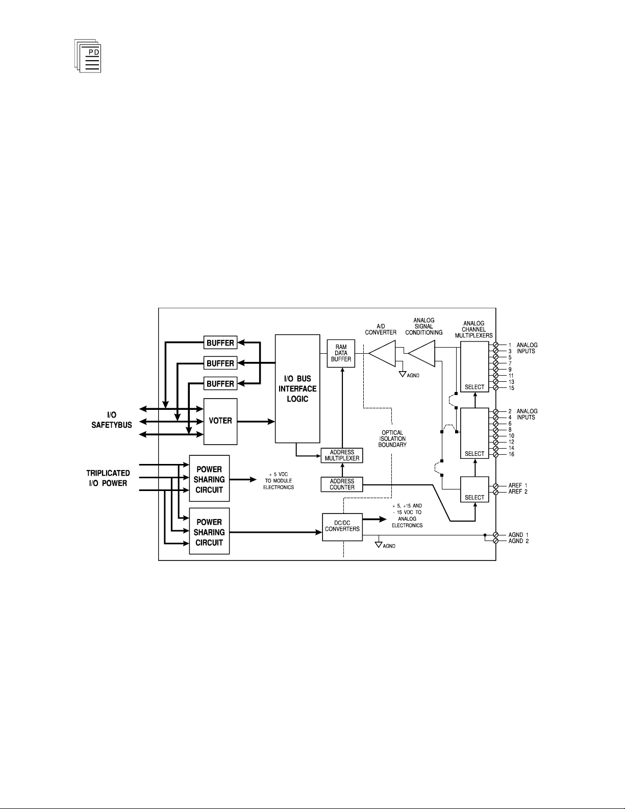
A block diagram of the analog input module is shown in
Figure 1.
2
Figure 1. Block Diagram of Analog Input Module.
Analog field signals are conditioned and multiplexed into an
analog-to-digital (A to D) converter and converted into 12-bit
digital data. These digital values are stored in the module’s
RAM. The digital logic circuits are optically isolated from the
analog field signals to protect the logic circuits from external
field signal transients and over voltages.
Industrial Control Services
Page 3
Analog Input Modules
The processor modules send triplicated read data requests to
the analog input module over the I/O Safetybus. The
processors’ addressing data and data read requests are voted
by the module (preventing I/O Safetybus failures upstream
from the module from affecting module operations). The voted
result is then passed to the I/O bus interface logic.
After receiving the voted data read request, the I/O bus
interface logic retrieves the analog data values from the RAM
and places the data into the module’s three bus drivers. Each
of the three bus drivers is independently powered and
controlled (by the I/O transceiver modules) — preventing
failures in a single driver from propagating to the other two /O
busses. The bus drivers then transmit the data via the
backplane I/O Safetybus to the I/O transceiver modules which,
in turn, transmit the data to the processors.
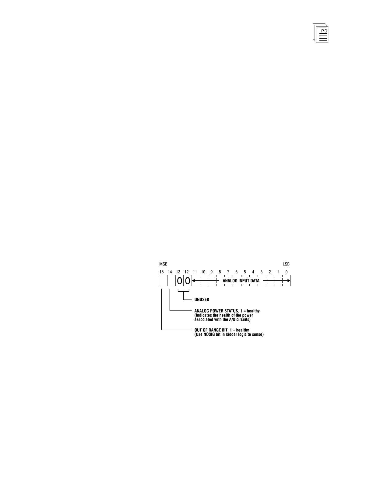
The 12-bit analog input data is packaged as a 16-bit integer.
In this format the analog data is the least significant bits,
providing analog input data ranging from 0 to 4095. Two of
the remaining four bits are used to flag alarms as shown in
Figure 2.
(T7420A, AF)
Figure 2. Analog Input Data Format.
Testing and
Each module’s voter circuits are periodically tested by the
processor modules. Discrepant data are sent through one of
three legs of the I/O Safetybus to determine whether the
module’s voter is able to outvote the incorrect data. A failure
to return the correct majority-voted result to the processors
Diagnostics
PD-7023
Mar-06
3
Page 4

Analog Input Modules
produces an I/O module error indication at the processor
modules and a module fault indication at the I/O module.
Each type of module has a unique identification code that is
read by the controll
which type of module is installed in each I/O chassis slot and
how to address that module and its points specifically. If a
module is removed, or is replaced with a module of a different
type, the processor modules will indicate an I/O module error.
Loopback logic tests periodically write data to the module and
then read it back to determine whether the module’s I/O bus
interface logic is functioning correctly.
(T7420A, AF)
er. This code lets the controller know
Front Panel Indicators
Figure 3 shows the physical features of the analog input
modules. The front panel of each module contains active and
fault status indicators.
Active and Fault Status Indicators
These green and red LEDs indicate the overall health of the
module. During normal operation the green ACTIVE
indicator flashes at the controller's scan rate. If a module
fault occurs the red FAULT indicator turns on and the green
ACTIVE indicator turns off.
4
Industrial Control Services
Page 5

Analog Input Modules
(T7420A, AF)
PD-7023
Mar-06
Figure 3. Analog Input Module.
5
Page 6

Voltage Ranges
Current Ranges
(using external 250 Ohm resistor)
0 to 5 Vdc
0 to 20 mA
1 to 5 Vdc
4 to 20 mA
-
5 to +5 Vdc
-
20 to +20 mA
0 to 10 Vdc
0 to 40 mA
-
10 to +10 Vdc
-
40 to +40 mA
Analog Input Modules
(T7420A, AF)
Application
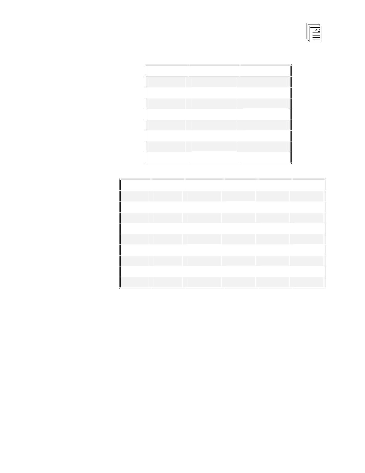
Analog Input Range Selection
The possible input voltage ranges are the same for both
differential and single-ended modes. Since current
measurements are converted to voltages using external
precision resistors, the same voltage ranges apply. Choices of
input voltage ranges include unipolar, bipolar, and offset
ranges. All ranges are selected by setting jumpers located
inside the module.
Table 1. Analog Input Ranges.
Input Out of Range Detection
If the analog signal is well beyond the normal operating range
selected, the NOSIG contact associated with the analog point
will be enabled. Note that there are some out-of-range signals
that do not set the NOSIG bit. The out of range thresholds for
each input range are shown on page 27.
Absolute Signal Ranges
The absolute workin
from -10.3 volts to +10.3 volts with regard to AGND (analog
ground). The acceptable common mode voltage range (either
differential or single-ended with regard to its appropriate
analog reference input) is from -10.3 volts to +10.3 volts.
g range for any analog input signals is
6
Industrial Control Services
Page 7

Analog Input Modules
(T7420A, AF)
Sampling Speed
The rate at which each of the analog input channels is
sampled depends upon the mode of operation. Each channel
is given a 225 msec time slot during the multiplexing process.
During that time s
measuring system, the measuring system is allowed to settle,
the settled value is sampled (and held), and is then converted
to a 12-bit value by an analog-to-digital converter. The
channels are sampled in numerical order. In single-ended
mode, the 16 channels are sampled in 3.60 msec on a
continuous repeating basis. In differential mode, the eight
channel pairs are sampled in 1.80 msec on a continuous
repeating basis. Converted data are stored in the module’s
R
AM and can be accessed by the controller. Data for a given
channel is available at the previously stored value until an
updated conversion replaces it.
Sampling speed is unrelated to internal access speed within
the Regent system. Programming and other features
determine how often the Regent system can access the
converted data. There are no “lockout times” when the Regent
system is prevented from reading the current stored values of
the converted data.
lot, the input voltage is connected to the
PD-7023
Mar-06
Single-Ended References
When single-ended input mod
reference for all eight signals on the same input field wiring
terminal block is AREF1 on the top terminal block and
AREF2 on the bottom. This ground reference may be
different from the external I/O analog ground AGND also
available on the same connector. When used with the I/O
Termination Assembly (see PD-7901), both AREF1 and
AREF2 are isolated from AGND by 1K Ohm resistors.
When the single-ended signals are measured, the appropriate
ground reference for the signal is selected by another
multiplexer on the board, and becomes the reference for the
measurement. In differential mode, AREF1 and AREF2 are
not used as references.
7
e is selected, the ground
Page 8

Analog Input Modules
(T7420A, AF)
Input Over Voltage Protection
All analog inputs, regardless of mode and analog references
(AREF1 and AREF2), are protected from over-voltages (these
ranges are shown on page 27).
Current Measurement Considerations
Precision resistors external to the module are required to
convert currents to voltages that can be measured directly by
the module. The resistors can be mounted on field marshaling
terminals or are provided using the appropriate analog input
termination blocks. For differential current measurements,
both sides of the external resistor are brought onto the
module.
It is possible to mix current and voltage measurements on the
same module as long as they can work with the same voltage
range selected. In the case of single-ended measurements,
this either requires that both current and voltage
measurements are referenced to the sa
(AREF1 or AREF2), or that voltage inputs be on one set of
eight inputs and current inputs on the other set.
me reference point
Input Range and Mode Selection Jumpers
The jumpers that determine the mode and input range for the
module are set at manufacturing time for an input range of 1
to 5 volts and the 16-channel, single-ended input mode. If
other input ranges or another mode is desired these jumpers
must be repositioned to the appropriate settings.
There are 17 jumper locations that are used. They are
summarized in Tables 2 and 3, below. The module’s cover
must be removed to access and reposition the jumpers.
8
Industrial Control Services
Page 9
Analog Input Modules
Jumper
Single-Ended
Differential
J251
n
J252
n
J501
n
J502
n
J503
n
J504
n
J505
n
J701
n
Jumper
0 to +10
-
10 to +10
+1 to +5
0 to +5
-
5 to +5
J551
n
J552
n
n
J553
n
n
J601
n
n
n
J602 n
n
J651 n
n
J652
n
n
n
J653
n
n
n
J654 n
n
(T7420A, AF)
Table 2. Mode Selection.
Table 3. Input Range Selection.
Input Low-Pass Filters
Two rows of jumper connections (J506 and J507) allow
selection of onboard capacitors to create single-pole low-pass
input filters on the board. Jumpers are placed on these
connections to select either single-ended or differential filters
as appropriate.
I
n single-ended mode, the filtering is done with respect to the
appropriate AREF1 (or AREF2) input line. A 10K Ohm
resistor is in series with each analog input line (this resistor is
also a part of the over voltage protection system for the
module as well), and the capacitor is on the multiplexing side
of the resistor. There are four rows of eight pins labeled J506
and J507, for single-ended mode filtering install jumpers
across row J506 and row J507 (for a total of 16 jumpers).
PD-7023
Mar-06
9
Page 10

Analog Input Modules
(T7420A, AF)
In differential mode, a 10K
Ohm resistor is in series with each
input line of each input analog channel pair. The capacitors
are placed on the multiplexing side of the resistors. The
filtering is then differential. There are four rows of eight pins
labeled J506 and J507, for differential mode filtering install
jumpers between rows J506 and J507 (for a total of eight
jumpers).
Frequency response data for the T7420A and T7420AF is
provided on page 27.
10
Industrial Control Services
Page 11

Analog Input Modules
(T7420A, AF)
PD-7023
Figure 4. Analog Input Configuration Jumper Locations.
Mar-06
11
Page 12

Analog Input Modules
(T7420A, AF)
Simplex Configuration
Analog input modules provide a suitable interface to non
critical input signals. Although many of the circuits in the
analog input modules are automatically tested and
annunciated, some logic circuits and all of the field-side
sensing circuits are simplex and non-tested. This simplex
input configuration is illustrated in Figure 5.
Figure 5. Simplex Ana
log Input Configuration.
-
Fault Tolerant Configurations
For critical inputs, redundant input modules are used in a
2oo3 or 1oo2 fault tolerant configuration. In these
configurations the redundant input modules are connected to
single or multiple sensors. If redundant sensors are installed
in the field, the redundant modules are connected so that each
sensor connects to one of the redundant modules. These
configurations are illustrated in Figure 6, showing triple
redundant input modules. Each analog input module is hot
replaceable. In redundant input configurations, if a fault
occurs on one module, it can be removed and replaced while
the system continues to sense the inputs from the remaining
two input modules.
12
Industrial Control Services
Page 13

Analog Input Modules
(T7420A, AF)
PD-7023
Mar-06
Figure 6. Fault Tolerant Analog Input Configurations.
Field Wiring
For field wiring details, refer to PD-7901 - I/O Termination
Assembly.
13
Page 14

Analog Input Modules
(T7420A, AF)
Keying
The I/O chassis can be physically keyed to prevent accidental
damage caused by inserting a module into a slot wired for a
different module type. Figure 7 illustrates how the slot keys
are installed on the I/O chassis slot field wiring connectors.
The slot key positions for the analog input modules are listed
in Table 4.
14
Figure 7. Installing Slot Keys.
Industrial Control Services
Page 15

Analog Input Modules
Module
Upper
Connector
Lower
Connector
T7420A
9 15
T7420A
F
9 15
Important!
(T7420A, AF)
Table 4. Slot Key Positions.
Configuration
Each input module is configured using the
W
INTERPRET
I/O
Configuration Editor. In the editor, you will perform the
three steps described below to configure the input module.
1) Set the Module Type:
Position the cursor on the module slot you wish to define.
Choose Set Module Type from the Edit Menu and select
the appropriate analog input module from the list.
There are four different analog input module types listed
in the Set Module Type dialog. Be sure to select the
app
ropriate module, i.e. standard response (T7420A) vs.
fast response (T7420AF) and single-ended (16-channel) vs.
differential (8-channel).
2) Edit the Module Definition:
Choose Edit Module Definition from the Edit Menu. A
dialog box will open where you can define the input point
definitions. Single-ended analog input modules will show
sixteen points that you can configure, while differential
analog input modules will show eight points that you can
configure.
PD-7023
Mar-06
15
Page 16

Analog Input Modules
(T7420A, AF)
Figure 8. Analog Input Module De
3) Edit each point:
finition.
Position the cursor on a Point definition and choose Edit
from the Module Definition dialog box to define a name
and description for each I/O point. In the Analog Input
Point dialog, enter a tag name (up to 12 characters) and a
description (up to 40 characters). The tag names are used
in the application program to represent the value of the
analog input in your control algorithms and interlocks.
Figure 9. Defining an Analog Input Point.
16
Programming
Inputs are referenced in the application program through the
tag names defined in the I/O Configuration Editor. The
analog inputs will range in value from 0 to 4095 over the
voltage range configured for the analog input module. Most
Industrial Control Services
Page 17
Analog Input Modules
(T7420A, AF)
often you will want to scale the analog input values to a more
convenient engineering unit number range.
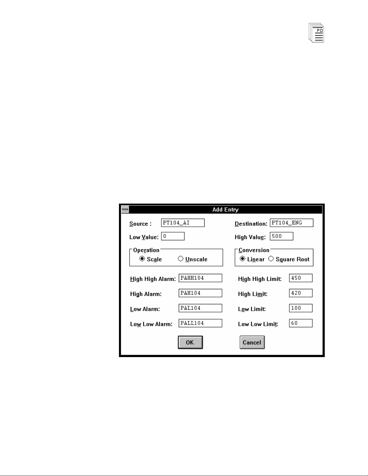
Scaling Analog Inputs
The scaling function block is used to convert the raw 0 to 4095
units of the analog input to an engineering unit number. The
result of this scaling conversion is usually stored in a shared
variable register that you define in the shared variable editor.
After scaling the analog input to a register, you can use the
register tag name in your applications to work with the
process variable in engineering units.
An example of an analog scaling entry is shown in Figure 10.
For more details about configuring analog scaling function
blocks refer to Using the Analog Scaling Editor in Section 5
Working with Programs and Function Blocks in the Regent
User’s Guide.
PD-7023
Mar-06
Figure 10. Analog Scaling Example.
17
Page 18

Analog Input Modules
(T7420A, AF)
Programming Fault Tolerant Analog Inputs
To program fault tolerant configurations using triplicated
analog input modules, a midvalue element can be used as
shown in Figure 11.
Figure 11. Programming Fault Tolerant Analog Inputs.
In this illustration, VALUE_A_NAME, VALUE_B_NAME,
and VALUE_C_NAME represent the three analog inputs to
be mid-value selected. ERROR_A_NAME,
ER
ROR_B_NAME and ERROR_C_NAME are the error bits
for the analog inputs. RESULT_NAME is the result of the
mid-value instruction. The field Limit is the integer value, in
similar units to the Value A, B and C variables, that an
analog input can deviate from the mid-value result before
signaling an error (via the Error A, B or C bits). Once an
error bit is set, it is latched. RESET_NAME is the reset bit
used to reset the latched error bits.
Maintenance
18
There are no user-replaceable parts inside the module.
Modules must be calibrated for the particular input range
within which they will operate. All modules are calibrated
before being shipped by ICS; however, modules require
calibration whenever:
· the module is configured for a different operating voltage
range (factory configuration is 1 to 5 VDC),
· the module is configured for a different operating mode
(factory configuration is 16 channel, single-ended), or
· once per year after installation, to adjust for drift in the
analog circuitry. Drift rates are
Specifications, below. These drift rates should be used to
listed under
Industrial Control Services
Page 19

Analog Input Modules
(T7420A, AF)
help you determine the frequency for checking the
calibration of the modules in your installation.
Calibration Methods
Calibrating the analog input module requires that you
connect calibration voltages to all of the analog input
channels of the module and adjust the trimming
potentiometers until the analog inputs read the correct
calibration values. During calibration the module must be
installed in a Regent system and disconnected f
rom the field
signal wiring while the calibration voltages are connected to
the module input signals.
There are three trimming potentiometers which are accessible
through the front face of the module making calibration
adjustments possible without opening the module’s cover.
However, the corresponding field wiring will have to be
disconnected from the I/O chassis terminals.
If you do not wish to disturb the field wiring during
calibration, the I/O Extender module (catalog T3322), can be
used. With the analog input module PCB removed from the
module housing and plugged into the I/O extender module,
you can connect the calibration voltages to the I/O extender
module and leave the analog input field wiring in place. This
is the recommended method for calibrating the analog inputs.
and is described below in the calibration procedure.
PD-7023
Mar-06
Calibration Procedure
Equipment Required
·
DC signal source with a range from -10 VDC to +10 VDC @
10 mA minimum and with an accuracy and resolutio
better than 100 mVDC.
·
Potentiometer adjustment tool.
·
Phillips screwdriver
·
I/O module extender, catalog number T7322
(recommended).
·
PC running the
analog input channel values during calibration.
W
INTERPRET
n of
software, used to monitor the
19
Page 20

Important!
Analog Input Modules
(T7420A, AF)
Calibration Preparation
The module must be calibrated while connected to an I/O
chassis of an operational Regent
system.
During calibration, the analog input module will be
disconnected from the actual field devices. Appropriate
precautions should be taken to ensure that the disconnection
of the field sensors does not pose a safety risk to plant
personnel or process equipment.
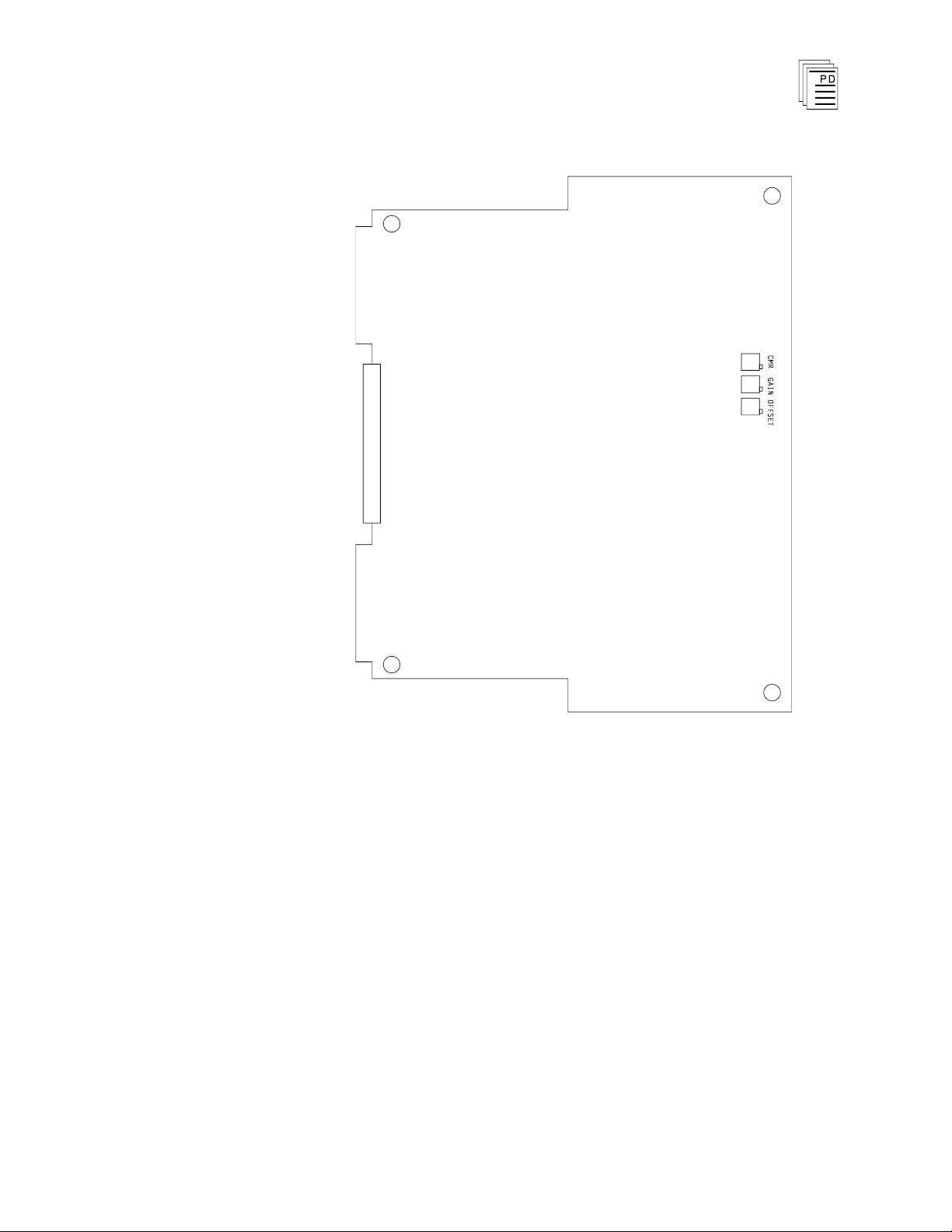
There are Offset, Gain and CMR (Common Mode Rejection)
potentiometers that are common to all of the analog input
channels. These potentiometers are located on the front of the
analog input PCB (see Figure 12).
During the calibration
procedure the Offset and Gain potentiometers will be adjusted.
The CMR potentiometer is factory adjusted and does not
require adjustment in the field.
20
Industrial Control Services
Page 21
Analog Input Modules
(T7420A, AF)
PD-7023
Mar-06
Figure 12. Analog Input Module Calibration Potentiometer
Locations.
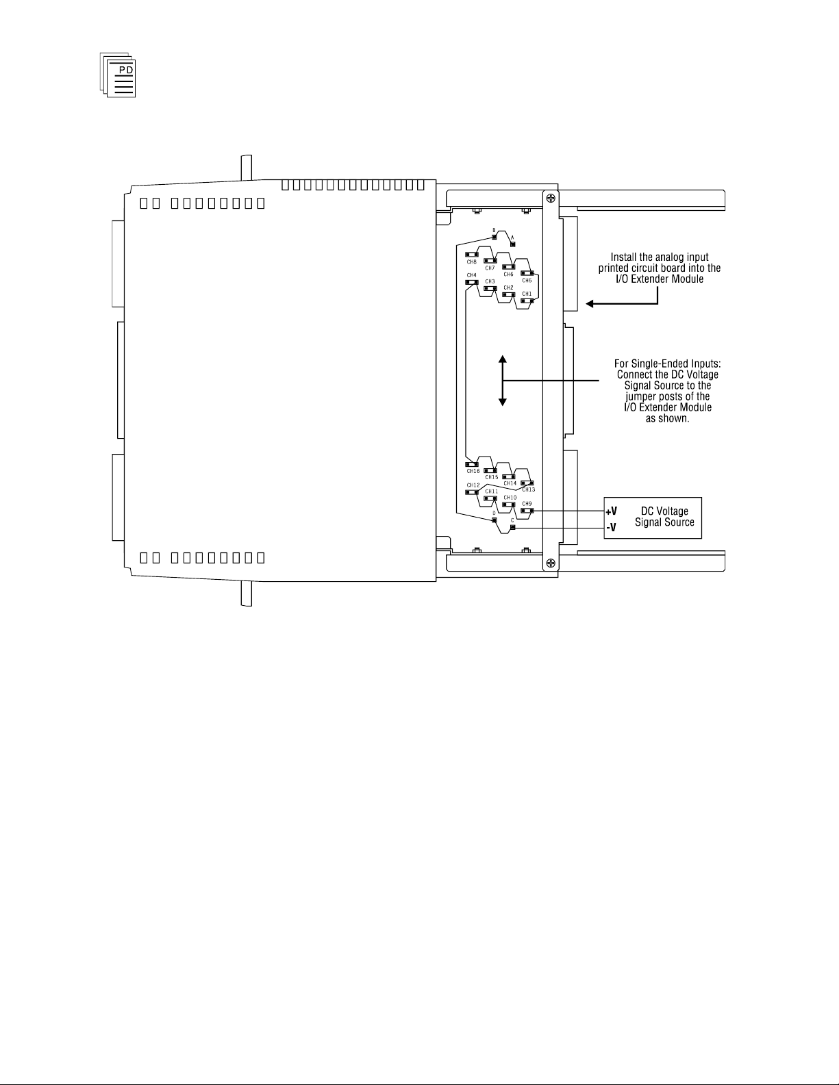
The I/O extender module has jumper posts that allow you to
connect or disconnect the I/O slot field wiring on the I/O
chassis to the printed circuit board plugged into the I/O
extender. During the calibration steps yo
u will remove any
jumpers installed on these posts in order to connect the DC
voltage signal source to the analog inputs. For modules
configured for 16-channel, single-ended inputs, Figure 13
shows the jumper posts to which you should connect the signal
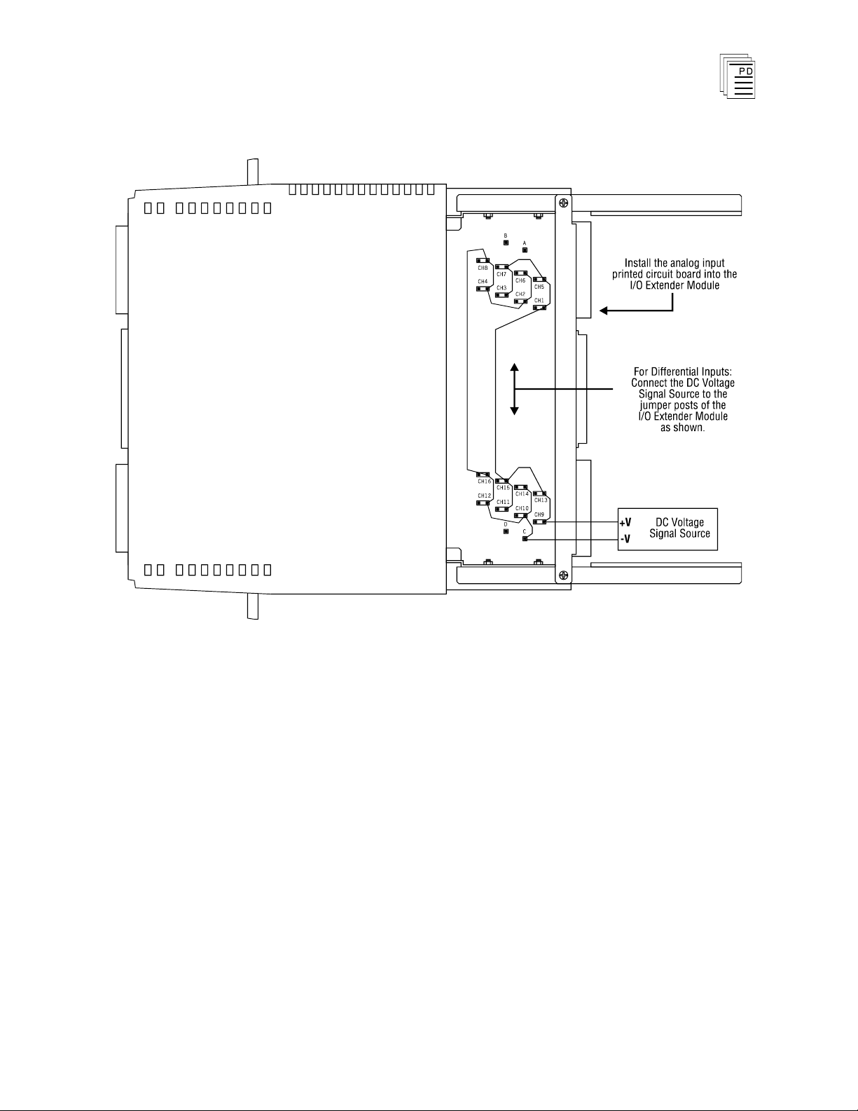
source for each analog input channel. For modules configured
for 8-channel, differential inputs, Figure 14 shows the jumper
posts to which you should connect the signal source for each
analog in
put channel.
21
Page 22
Analog Input Modules
(T7420A, AF)
Figure 13. I/O Extender Connections for Single-Ended Analog Input Calibration.
22
Industrial Control Services
Page 23
Analog Input Modules
Important!
(T7420A, AF)
Figure 14. I/O Extender Connections for Differential Analog Input Calibration.
Within each pair of jumper posts, make sure that you connect
the voltage source to the jumper posts nearest the front of the
I/O extender. Do not make any connections to the jumper
posts nearest the I/O chassis backplane —
these connect to the
actual field wiring attached to the I/O slot terminals on the I/O
chassis.
Calibration Steps
1. Remove the module to be calibrated from the I/O chassis.
2. Install the I/O extender module into the slot from which
the module was removed.
3. Remove the jumpers (if installed) labeled CH1 through
CH16 from the I/O extender module.
PD-7023
Mar-06
23
Page 24

Analog Input Modules
4. Connect the DC voltage signal source to the I/O extender
5. Remove the four screws on one side of the module and
6. Install the printed circuit board into the I/O extender
7. Adjust the DC voltage source to the Offset Input Voltage
(T7420A, AF)
jumper posts as shown in Figures 13 or 14.
as required to make the connections.
Use test clips
remove the printed circuit board from the module
clamshell housing.
module. Allow the board to warm up for approximately one
minute.
value indicated in Table 5 for the configured input range
of the input module. Wait approximately one minute for
the analog
inputs to stabilize.
8. Using the monitoring functions of
W
INTERPRET
, monitor
the values of all the analog input channels. Refer to the
Regent User’s Guide for more details about the monitoring
functions.
9. Adjust the Offset potentiometer (R569) for an average
reading of 2 ±1 for all input channels. Verify that all input
channels read between 1 and 3. If one or more channels
reads significantly different, return the module to ICS for
repair.
10. Adjust the DC voltage source to the Gain Input Voltage
v
alue indicated in Table 5 for the configured input range
of the input module. Wait approximately one minute for
the analog inputs to stabilize.
11. Adjust the Gain potentiometer for a reading of 4093 ±1 for
all channels. Verify that all input channels read between
4092 and 4094. If one or more channels reads significantly
different, return the module to ICS for repair.
12. Repeat steps 7 through 11 and make adjustments if
necessary until both the Offset and Gain values read
corre
ctly. There is some interaction between the Offset and
Gain adjustments so often you will need to repeat these
steps a few times until both the Offset and Gain readings
read correctly without further adjustments.
24
13. Calibration is complete. Unplug the printed circuit board
from the I/O extender module and replace it in its
Industrial Control Services
Page 25

Analog Input Modules
Configured Voltage
Range
Offset Input Voltage
Gain Input Voltage
0.00 to +10.00 volts
0.0049 VDC
9.9951 VDC
-
10.00 to +10.00 volts
9.9902 VDC
9.9902 VDC
+1.00 to +5.00 volts
1.0020 VDC
4.9980 VDC
0.00 to +5.00 volts
0.0024 VDC
4.9976 VDC
-
5.00 to +5.00 volts
4.9951 VDC
4.9951
VDC
(T7420A, AF)
clamshell housing. Remove the I/O extender module from
the I/O chassis and reinstall the calibrated module in the
I/O chassis.
The module’s red Fault indicator will be on until you
pe
rform a voted reset by pressing the Reset buttons on two
of the Regent processor modules. After the voted reset is
complete, the module’s green Active indicator should turn
on.
Safety Considerations
Table 5. Analog Calibration Voltages.
The analog input modules are TÜV certified as non
interfering and when properly configured are also certified for
Risk Class 5 safety critical inputs. Safety critical
configurations include midvalue selection methods.
In safety critical input applications using a single sensor, it is
important that the sensor failure modes be predictable and
well understood, so there is little probability of a failed sensor
not responding to a critical process cond
ition. In such a
configuration, it is important that the sensor be tested
regularly, either by dynamic process conditions that are
verified in the Regent, or by manual intervention testing.
-
PD-7023
Mar-06
Redundant sensors can be used with redundant input
modules to eliminate any single points of failure and extend
fault tolerance to include the sensors.
For additional safety considerations, please refer to the Safety
Considerations section of the Regent User’s Guide.
25
Page 26

Safetybus Power
1.85 load units
Numbe
r of Inputs
Eight differential or 16
single-ended (jumper
selectable)
Inputs Per Group
Eight single-ended or four
differential
Ranges
Voltage:
Current:
(using external 250W resistors)
0.00 to +10.00 volts
-
10.00 to +10.00 volts
+1.00 to +5.00 volts
0.00 to +5.00 volts
-
5.00 to +5.00 volts
0.00 to +20.00 mA
-
40.00 to +40.00 mA
+4.00 to +20.00 mA
0.00 to +20.00 mA
-
20.00 to +20.00 mA
External Power
None for module electronics;
however, analog field loop
power is not s
upplied by the
module
Accuracy and Drift
(Accuracy/Drift)
-
10 to +10 volts:
0.00 to +10.00 volts:
-
5.00 to +5.00 volts:
0.00 to +5.00 volts:
+1.00 to +5.00 volts:
Note: Initial accuracy (% of span)
represents the initial accuracy @
22ºC to 28ºC calibration
temperature.
0.12%/100 ppm/
°C
0.08%/55 ppm/
°C
0.13%/110 ppm/
°C
0.10%/65 ppm/
°C
0.10%/70 ppm/
°C
Analog Input Modules
(T7420A, AF)
Specifications
26
Industrial Control Services
Page 27

Analog Input Modules
Out of Range Thresholds
Over-range
-
10.00 to +10.00 volts:
0.00 to +10.00 volts:
-
5.00 to +5.00 volts:
0.00 to +5.00 volts:
+1.00 to +5.00 volts:
Under-range
-
10.00 to +10.00 volts:
0.00 to +10.00 volts:
-
5.00 to +5.00 volts:
0.00 to +5.00 volts:
+1.00 to +5.00 volts:
Expressed in volts:
+10.30 min., +10.70 max.
+10.30 min., +10.70 max.
+5.15 min., +5.35 max.
+5.15 min., +5.35 max.
+5.12 min., +5.28 max.
-
10.30 min., -10.70 max.
-
0.30 min., -0.70 max.
-
5.15 min., -5.35 max.
-
0.15 min., -0.35 max.
+0.88 min., +0.72 max.
Over
Voltage Protection
Powered
AI1-AI16:
AREF 1,2:
Acceptable Duration:
Unpowered
AI1-AI16:
AREF 1,2:
Acceptable Duration:
±60 VDC/85 VAC RMS/±400 VDC
±40 VDC/55 VAC RMS/±60 VDC
Indefinite/Indefinite/1 msec
±45 VDC/45 VAC RMS/±400 VDC
±25 VDC/25 VAC RMS/±45 VDC
Indefinite/Indefinite/1 msec
Frequency Response
(-
3 dB/-30 dB/Atten. @ 60 Hz)
Single-Ended
T7420A:
T7420AF:
Differential
T7420A:
T7420AF:
7.23 Hz/229 Hz/18.4 dB
10.6 KHz/335 KHz/0.0 dB
3.62 Hz/114 Hz/24.4 dB
5.31 KHz/168 KHz/0.0 dB
Data Update Rate
Single-ended or 16
channel mode:
Differential or 8-channel
mode:
3.60 msec on a continuous
repeating basis
1.80 msec on a continuous
repeating basis
Isolation
2500 volts minimum (field
wiring to control logic)
Heat Dissipation
9 Watts, 31 BTUs/hour
(T7420A, AF)
PD-7023
Mar-06
27
Page 28

Operating Temperature
0°
to 60° C
(32° to 140° F)
Storage Temperature
-40°
to 85° C
(-40°
to 185° F)
Operating Humidity
0 to 95% relative humidity,
non-condensing
Vibration
10 to 55 Hz:
±0.15mm
Shock
Operating:
15 g, ½ sine wave, 11 msec
Electromagnetic
Interference
•
IEC 801 Part 2 - Electrostatic
Discharges
•
IEC 801 Part 3 - Radiated
Electromagnetic Fields
Level 3: Contact discharge of
6 kV
Level 3: 10 V/M, 27 MHz 500 MHz
Safety
Certified to D
IN V VDE
0801 for Risk Class 5. Also
designed to meet UL 508 and
CSA 22.2, No. 142-M1981
Dimensions
Height:
Width:
Depth:
12.6" (320 mm)
1.27" (32 mm)
10.12" (257 mm)
Weight
3.0 lbs (1.4 kg)
Analog Input Modules
(T7420A, AF)
28
Industrial Control Services
Page 29

Analog Input Modules
Function
Signal
Mode
Value
I leakage
AI1 through AI16
—
50 nanoA (max.)
Rin (re AGND)
AI1 through AI16
—
100 Mohm (min.)
Rin (re AREF2)
AREF1
—
100 Mohm (min.)
Rin (note 1)
AI1 through AI16
SE
100 Mohm (min.)
CMR (note 2)
AI1 through AI16
SE
51 dB min.
CMR (note 3)
AI1 - AI16
SE
41 dB min.
CMR (note 4)
AI1 through AI16
SE
66 dB min.
NMR (note 5)
AI1 through AI16
SE
(note 5)
Rin (re AGND)
AI1/2 - AI15/16
DIFF
100 Mohm (min.)
CMR (note 6)
AI1/2 - AI15/16
DIFF
72 dB min.
CMR (note 7)
AI1/2 - AI15/16
DIFF
49 dB min.
CMR (note 8)
AI1/2 - AI15/16
DIFF
81 dB min.
NMR (note 9)
AI1/2 - AI15/16
DIFF
(note 9)
Notes:
1) AI1 through AI8 are referenced to AREF1. AI9 through AI16 are
referenced to AREF2.
2) CMR: DC to 20 kHz, AI1-AREF1 through AI8-AREF1, AI9-AREF2
throug
h AI16-AREF2. Referenced to AGND (model T7420A).
3) CMR: Same as note 2 except model T7420AF.
4) CMR: 60Hz, AI1-AREF1 through AI8-AREF1, AI9-AREF2 through AI16
-
AREF2. Referenced to AGND.
5) Normal mode rejection (single ended).
6) CMR: DC to 20 kHz, Differential signal referenced to AGND.
7) CMR: Same as note 6 except model T7420AF.
8) CMR: 50 Hz, Differential signal referenced to AGND.
9) Normal mode rejection (differential).
(T7420A, AF)
Miscellaneous Input Circuit Specifications
PD-7023
Mar-06
29
 Loading...