

Page 1
ICS Regent +Plus
PD-7009
I/O Transceiver Modules
I/O transceiver modules provide an interface between the
processor modules in the controller chassis and the I/O modules in
the I/O chassis. Three I/O transceiver modules are installed in the
three left slots of each I/O chassis.
Features
• Three modules per I/O chassis for triple redundant operation.
®
I/O XCVR
(T7310)
Issue 1, September, 04
• Interfaces processor modules to I/O modules.
• Hot replaceable.
• Front panel indicators on each module show active and fault
status.
• TÜV certified for safety, Risk Class 5.
I/O transceiver modules are triple redundant and can be removed
and replaced without interrupting system operation.
Module Operation
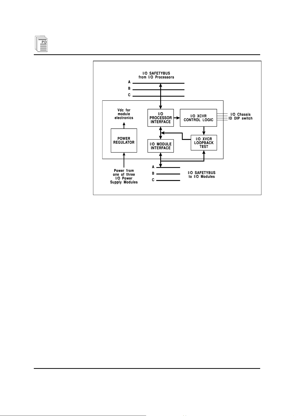
A block diagram of a typical I/O transceiver module is shown in
Figure 1.
Each I/O transceiver module communicates with one of the three
processor modules in the controller assembly. During I/O
Safetybus communications, the control logic on the I/O transceiver
module reads the I/O chassis’ identification code from the I/O
commands and compares them to the chassis’ identification switch
settings. Appropriately addressed I/O commands are directed
along the chassis’ backplane Safetybus to the I/O modules.
Industrial Control Services (Issue 1) 1
Page 2
I/O Transceiver Modules (T7310)
Figure 1. Block Diagram of I/O Transceiver Module.
I/O module responses are buffered and transmitted back along the
chassis’ backplane Safetybus to the I/O transceiver, and from the
I/O transceiver along the I/O Safetybus cable to the processor
modules.
Triplicated power is cabled into the I/O chassis and distributed to
the I/O transceiver modules. Each I/O transceiver module
receives power from one of the three I/O power supplies. Power
regulation circuits in the I/O transceiver modules provide the
necessary regulated voltages for the module’s electronics. Should a
single power supply fail, an interlock signal from the failed power
supply will cause the I/O transceiver it normally powers to shut
down.
2 (Issue 1) Industrial Control Services
Page 3

I/O Transceiver Mo dules (T7310)
Testing and Diagnostics
Loopback tests, periodically sent from the processor modules, are
used to test the health of the I/O transceiver modules.
All detected failures produce an I/O module error indication on
the processor modules and a module fault indication on the I/O
transceiver module.
Front Panel Indicators
Figure 2 shows the physical features of the I/O transceiver
modules. The front panel of each module contains active and fault
status indicators.
Active and Fault Status Indicators
These green and red LEDs indicate the overall health of the
module. During normal operation the green ACTIVE indicator is
on. If a module fault occurs the red FAULT indicator turns on and
the green ACTIVE indicator turns off.
PD-7009 Sep-04 (Issue 1) 3
Page 4

I/O Transceiver Modules (T7310)
Figure 2. I/O Transceiver Module.
4 (Issue 1) Industrial Control Services
Page 5

I/O Transceiver Mo dules (T7310)
Maintenance
No periodic maintenance or calibration is required for I/O
transceiver modules. There are no user replaceable parts inside
these modules.
Safety Considerations
The I/O transceiver modules are TÜV certified for Risk Class 5
safety critical applications.
Specifications
Safetybus Power
I/O Interface
Heat Dissipation
Operating Temperature
Storage Temperature
Operating Humidity
Vibration
10 to 55 Hz:
Shock
Operating:
Not applicable (included in
I/O power supply output
capacity, see PD-6008: I/O
Power Supply Modules)
One leg of triplicated I/O
Safetybus
8 Watts, 27 BTUs/hour
0° to 60° C
(32° to 140° F)
-40° to 85° C
(-40° to 185° F)
0 to 95% relative humidity,
non-condensing
±0.15mm
15 g, ½ sine wave, 11 msec
PD-7009 Sep-04 (Issue 1) 5
Page 6

I/O Transceiver Modules (T7310)
Electromagnetic
Interference
• IEC 801 Part 2 - Electrostatic
Discharges
• IEC 801 Part 3 - Radiated
Electromagnetic Fields
• IEC 801 Part 4 - Transients
and Bursts
• IEC 801 Part 5 - Surge
Immunity
• ANSI/IEEE C37.90 - Surge
Withstand Capability
Safety
Dimensions
Width:
Depth:
Height:
Level 3: Contact discharge of 6
kV
Level 3: 10 V/M, 27 MHz 500 MHz
Level 4: 2 kV, 2.5 kHz for t =
60 sec
Level 3: 2 kV
2.5 kV damped 1 MHz sine
wave
4 kV bi-directional impulse, 10
nsec rise time, fast transient
Certified to DIN V VDE 0801
for Risk Class 5. Also designed
to meet UL 508 and CSA 22.2,
No. 142-M1981
12.6" (320 mm)
1.27" (32 mm)
10.12" (257 mm)
Weight
3.0 lbs (1.4 kg)
6 (Issue 1) Industrial Control Services
 Loading...