

Page 1

ICS Regent +Plus
PD-7000
Processor Modules
110 VAC, 220/240 VAC and 24 VDC
(128K: T7110, T7111 and T7112)
(512K: T7120, T7121 and T7122)
The controller assembly's three processor modules store and
execute application programs, scan and update the I/O modules,
process communications, and detect system faults. Each of the
processor modules executes the application programs
independently, but in lock-step synchronization with the other two.
And each processor module independently communicates in lockstep synchronization with the I/O assembly over its own dedicated
I/O Safetybus link.
®
Issue 1, September, 04
Features
• Triple modular redundant, fault tolerant (3-2-0) operation.
• Two-out-three hardware voting of all internal operations.
• Automatic fault handling without nuisance alarming.
• Time-stamped fault historian.
• Hot replacement with pushbutton education of new module
(no need to re-load programs).
• Battery-backed program storage for power outage protection.
• Structured function block programming.
• Multiple program execution.
• Front panel indicators on each module show processor,
communications, I/O, program, battery, memory lock, and
power status.
• TÜV certified for safety, Risk Class 5.
The processor modules use a two-out-of-three voting scheme to
detect faults in the system. The Regent identifies, isolates, and
records transient and permanent faults as they occur. All faults are
recorded in the system's fault history. Permanent faults are also
Industrial Control Services (Issue 1) 1
Page 2
Processor Mo dules (T7110, 11, 12, 20, 21, and 2 2)
annunciated by an LED on the front of the processor module. In
addition, redundant fault contacts are activated to signal an
external device to alert operators to any permanent fault.
Module Operation
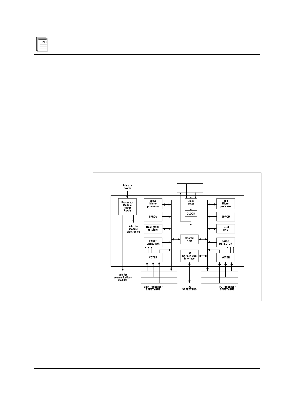
A block diagram of a typical processor module is shown in Figure
1.
Inside each processor module is a main processor, an I/O proc-
essor, and a power supply. A battery inside each of the processor
module maintains user application programs and the downloadable
portions of the system's RAMcode if there is a power failure. Each
processor module has interfaces to the processor Safetybus and the
I/O Safetybus. These interfaces consist of an input voter,
discrepancy detector logic, and an output driver.
Figure 1. Block Diagram of a Processor Module.
The voting and fault detection circuits allow the processor modules
to identify and isolate transient, intermittent, and permanent faults
as they occur. All faults are recorded in the system's fault history.
Each processor module contains its own power supply that
converts input power to the logic power levels used by the internal
processor circuits. The failure of one power supply will only effect
2 (Issue 1) Industrial Control Services
Page 3
Processor Mod ules (T7110, 11, 12, 20, 21, and 22 )
one processor module — allowing the other two modules to
continue operating — thus keeping the Regent on-line by virtue of
its majority two-out-of-three voting architecture.
Programs are stored in on-board battery-backed RAM. Program
instructions are fetched from each processor’s memory and
executed by the processors. Data from inputs are read from the
I/O modules in the I/O assembly. The main processor coordinates
the Regent’s activities and solves the application algorithms
programmed by the user. Outputs are driven by transmitting data
through the processor module’s I/O processor to the I/O assembly.
Communications between the main processor and the I/O
processor are maintained through shared RAM that is used as a
“mail box” for data transfers between the two processors.
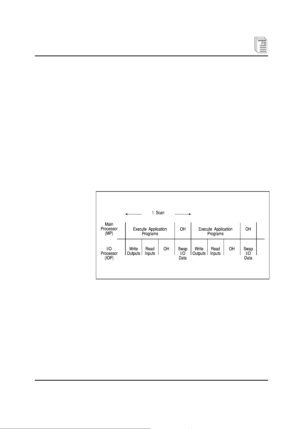
All three processor modules operate independently in lock-step
synchronization with the other two modules, continuously
repeating a scan cycle (Figure 2).
Figure 2. The Regent’s Scan Cycle.
The main processors in each of the three processor modules run
programs and process communications synchronously, while the
I/O processors in each module read and write I/O synchronously.
During these synchronous operations, all instructions and data are
distributed across the Safetybus where automatic voting and fault
detection occur.
Main Processor
During each scan cycle, the main processor executes application
programs, reading inputs from the shared RAM and writing
outputs to the shared RAM.
PD-7000 Sep-04 (Issue 1) 3
Page 4

Processor Mo dules (T7110, 11, 12, 20, 21, and 2 2)
In addition to running application programs, the main processor
takes care of system overhead, such as:
• Background diagnostics including voter tests, read tests of the
EPROMs, and read-write tests of the RAM (this automatic test
is also what re-educates a new processor).
• Communications processing including reading from and
writing to the communications modules every one millisecond
and checking the communications messages at the end of each
scan.
• Fault filtering and reporting (which are available through
W
INTERPRET’s fault status and fault history features).
• Reading the communications module’s real-time clock (if a
real-time clock communications module is installed).
I/O Processor
During each scan cycle the I/O processor receives voted input data
into its local RAM and transfers it to the shared RAM — making it
available to the main processor. After being processed by the main
processor, output data are placed into the shared RAM and read by
the I/O processor into its local RAM and written to the outputs.
The I/O processor also shares in managing system overhead. This
overhead includes:
• Background I/O processor tests (voter tests, read EPROM tests,
and read-write local RAM tests).
• I/O module tests (I/O module voter tests, logic loopback tests,
and coordinating other I/O module tests).
• Fault filtering and reporting (which are available through
W
INTERPRET’s fault status and fault history features).
Testing and Diagnostics
Each processor module’s error detection logic is periodically tested
to ensure its continued correct operation. Testing is done using
self-tests that are automatically scheduled by each processor
module’s real-time operating system.
Front Panel Indicators and Controls
Figure 3 shows the physical features of the processor modules. The
front panel of each module contains status indicators as well as a
reset button and a memory lock keyswitch.
4 (Issue 1) Industrial Control Services
Page 5
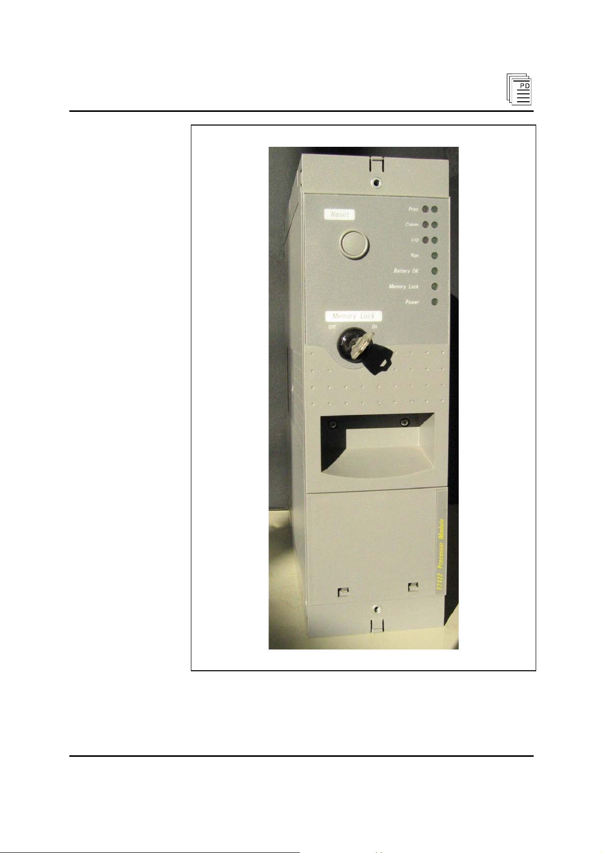
Processor Mod ules (T7110, 11, 12, 20, 21, and 22 )
Figure 3. Processor Module.
PD-7000 Sep-04 (Issue 1) 5
Page 6

Processor Mo dules (T7110, 11, 12, 20, 21, and 2 2)
Processor Indicator
This red and green LED pair indicates the overall health of the
processor module. During normal operation the green PROC
indicator is on. If a module fault occurs the red indicator turns on
and the green indicator turns off.
Communications Indicator
This red and green LED pair indicates the overall health of the
system’s communications. During normal operation the green
COMM indicator is on. If a communications fault occurs the red
COMM indicator turns on and the green COMM indicator turns
off.
I/O Indicator
This red and green LED pair indicates the overall health of the
system’s I/O. During normal operation the green I/O indicator is
on. If an I/O fault occurs the red I/O indicator turns on and the
green indicator turns off.
An I/O module failure causes all of the processor modules to
indicate an I/O fault. An I/O transceiver module, I/O power
supply module, or I/O Safetybus cable fault causes only the
associated processor module to indicate an I/O fault.
Run Indicator
This green LED is off if the Regent has cold-started (system powerup without 2oo3 validated programs). After the RAMcode is
loaded the Run LED flashes slowly (about ½ Hertz). With at least
one program loaded and running this indicator will flash faster
(about 2 Hertz).
The RUN indicator will be on steadily when an application
program scan exceeds the maximum allowable scan time
(approximately 200 milliseconds for the 128 kbyte modules, and
400 milliseconds for the 512 kbyte modules).
Battery Indicator
The green BATT OK indicator shows whether the module’s battery
has sufficient power to maintain the programs in the processor. If
the battery has adequate power, this LED will be on. If the battery
needs to be replaced this LED will be off .
Memory Lock Indicator
This green LED indicates whether the module’s memory lock
keyswitch is in the on or off position. The MEMLK indicator will
be green when the keyswitch is in the on position.
6 (Issue 1) Industrial Control Services
Page 7

Processor Mod ules (T7110, 11, 12, 20, 21, and 22 )
The system’s memory lock status is voted: If at least two processor
modules are locked, the system is memory locked, if at least two
processor modules are unlocked, the system memory is unlocked.
Power Indicator
The green POWER indicator is on when the module is receiving
adequate power and its internal power supply is healthy.
Reset Button
A reset button is used to initiate the voted reset function. A voted
reset clears system fault indicators after a fault has been detected
and a module has been removed and replaced.
Pressing the reset buttons on two operating modules performs a
voted reset. During a voted reset, the processors continue to
execute the application programs and fault reporting is temporarily
suspended. If a new processor module has been inserted it is
synchronized and automatically educated by standard diagnostic
tests performed by the system. At the end of the voted reset all of
the internal fault status bits are reset and normal fault reporting is
enabled.
Note:
The time it takes the system to complete a voted reset may range
from a couple seconds to a few minutes. Larger processor memory
sizes and application program scan times will result in longer voted
reset times. However, during the voted reset, the system always
continues to read and write I/O, solve application programs and
perform communications functions normally.
Memory Lock Keyswitch
The memory lock keyswitch is used to prevent changes or
modifications to the system’s application programs. When the
memory lock keyswitch is in the off position, programs can be
modified.
The system’s memory lock status is voted: If at least two processor
modules are locked the system is memory locked, if at least two
processor modules are unlocked, the system memory is unlocked.
In WINTERPRET developed systems, changing the memory lock
status from off (unlocked) to on (locked) automatically disables all
input and output forcing. Forcing can be restored only by
unlocking the system memory and enabling the force tables again
using WINTERPRET.
PD-7000 Sep-04 (Issue 1) 7
Page 8

Processor Mo dules (T7110, 11, 12, 20, 21, and 2 2)
Application
Processor module type should be selected based on the main input
power voltage (110 VAC, 220 VAC, or 24 VDC) and on memory
requirements (128 kbytes or 512 kbytes). Each memory size
supports all programming functions and up to 16 chassis of I/O.
Typically, systems with more that 300 I/O points will require 512
kbytes of memory due the larger program size, increased data
handling, etc.
Note:
In WINTERPRET developed systems, approximately 64K bytes of
memory are used to store the RAMcode portion of the operating
system (27K) and internal workspace memory (37K) required for
miscellaneous system features.
Maintenance
Each of the Regent's processor modules has a replaceable lithium
battery. These batteries provide sufficient backup power to prevent
loss of memory during a power failure.
The batteries have a shelf life of approximately 10 years. When
providing power to the module's memory during a power failure,
the battery can provide backup power to a processor module's
memory for approximately six months.
Battery Replacement
To replace the battery in a processor module, lift the cover at the
bottom of the front panel,by easing the two retaining clips with a
screwdriver. Carefully remove the battery clips from the battery. Fit
a new battery, taking care to route the wires back inside the
module. Close the cover.
Replacing the battery on a live module will not cause a shutdown.
8 (Issue 1) Industrial Control Services
Page 9

Processor Mod ules (T7110, 11, 12, 20, 21, and 22 )
EPROM Replacement
EPROM replacement is necessary only when upgrading to a new
version of the TRIOS operating system.
Important!
Important!
Because processor modules with different EPROM sets cannot
operate together in the same system, replacing EPROMs in an
installed system will require shutting down the entire Regent
system.
To prevent damage to module components when replacing
EPROMs always follow proper electrostatic discharge prevention
procedures during disassembly and handling. This includes the use
of ESD mats and wrist straps.
Module Removal
Loosen the retaining screw at the top of the module. Open the two
module release levers by rotating them outward (toward you).
Carefully pull the module out of the controller chassis.
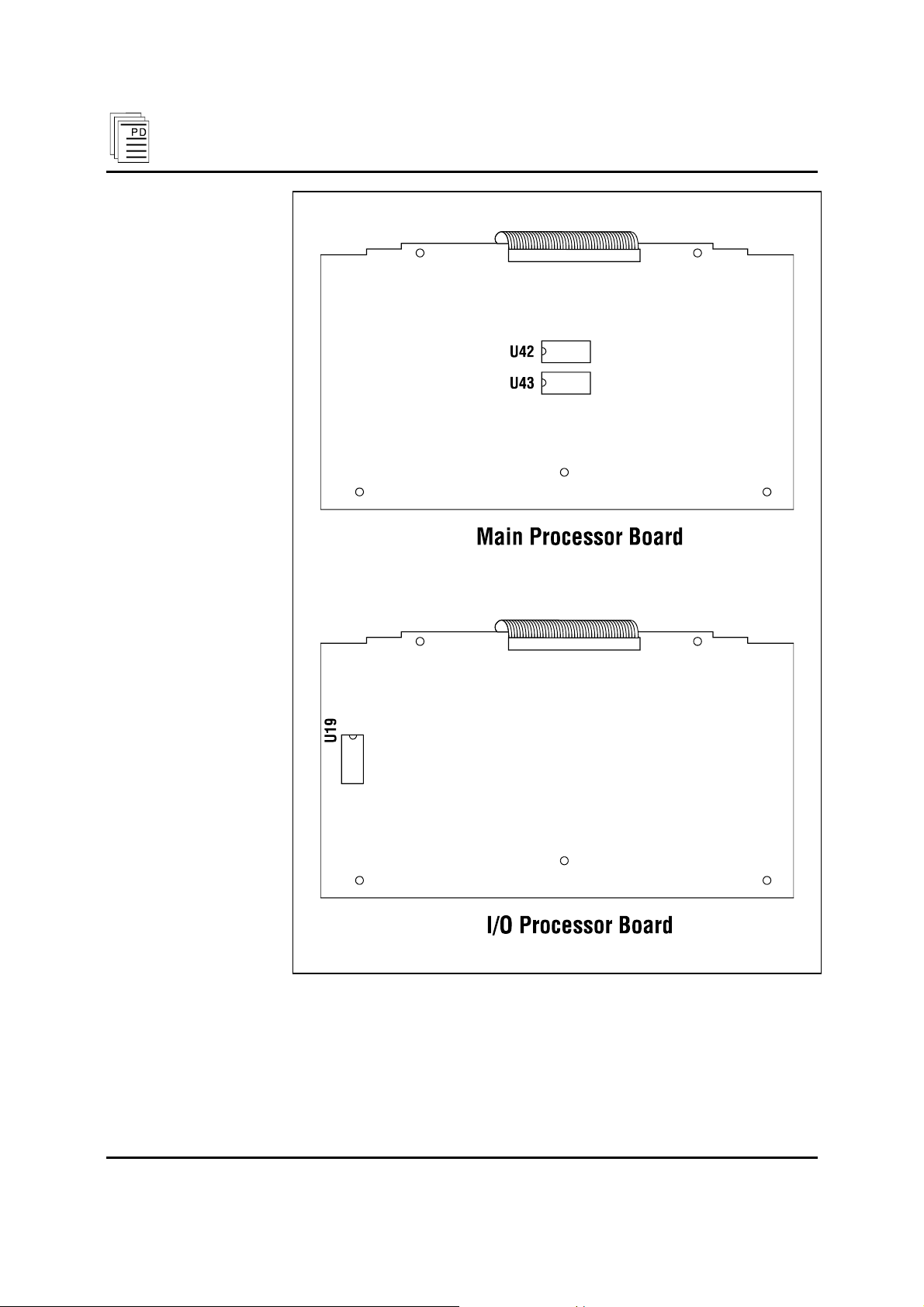
Replacing EPROMs
The three EPROMs in each module are labeled U42 and U43
(main processor) and U19 (I/O processor). Figure 4 shows the
locations of the EPROMs on each printed circuit board.
PD-7000 Sep-04 (Issue 1) 9
Page 10
Processor Mo dules (T7110, 11, 12, 20, 21, and 2 2)
Figure 4. Processor Module EPROM locations.
Remove EPROM U42 from the main processor board by rotating
the chip socket’s retaining clips outward. This will eject the chip
from its socket. Remove the old EPROM and place it on antistatic
foam off to one side.
10 (Issue 1) Industrial Control Services
Page 11

Processor Mod ules (T7110, 11, 12, 20, 21, and 22 )
Remove the new U42 EPROM from its packaging and inspect its
pins to make sure they are not bent.
Find the pin one index point (or notch) on the new EPROM.
Position the new EPROM in the chip socket so that the pin one
index point is facing the U42 label on the printed circuit board.
Carefully insert the new EPROM into the chip socket. It is often
easiest to align and partially insert the pins on one side of the chip
first, then align the other pins on the other side, and press the
EPROM carefully into place.
Before pressing the chip into place, check that all pins are properly
aligned in their respective holes. If the pins are not properly
aligned, carefully remove the chip and repeat the previous step.
Gently press the EPROM into the chip socket. As the EPROM is
pressed home the chip socket’s retaining clips will rotate inward to
secure the EPROM.
After fully inserting the EPROM, make a final check to ensure that
the pins are not bent, the pins are fully engaged and the EPROM
orientation is correct. If any pins are bent or the EPROM is not
oriented correctly, remove the EPROM and reinstall it.
Important!
If you install and apply power to a module with an EPROM
installed backwards the EPROM may be damaged. When the
EPROM is inserted backwards, power will be applied to incorrect
pins of the EPROM. If this happens, do not remove and re-insert
the same EPROM. Replace the incorrectly positioned EPROM
with a new EPROM.
Repeat the above steps for the U43 EPROM.
After installing the two new EPROMs in the main processor board,
rotate (or flip) the main processor board to one side to expose the
I/O processor board.
Locate the U19 EPROM on the I/O processor board and use the
steps described above to remove the old EPROM and install the
new EPROM.
PD-7000 Sep-04 (Issue 1) 11
Page 12

Processor Mo dules (T7110, 11, 12, 20, 21, and 2 2)
Reinstalling Modules
Reinstall the modules one at a time. To help make alignment
easier, install the first processor module in the left-most position,
the second module in the center position, and the third module in
the right-most position.
Open the two module release levers by pulling them toward you.
Carefully slide the module into the chassis. Be careful to keep the
module aligned while sliding it straight into the chassis.
The module should mount into the chassis with a minimum of
resistance. If the module does not mount easily, do not force it.
Remove it and check it for bent or damaged pins. If the pins look
okay, try reinstalling the module.
When the module is almost fully into the chassis, the release levers
will contact the chassis and begin to rotate closed. Press the levers
closed to seat the module in the chassis.
If the module does not seem to have seated correctly, open the
release levers and gently pull it back off the seat and out of the
chassis. Check for bent or damaged pins. If any pins are bent or
damaged do not install the module. Do not try to straighten bent
pins. Instead return the module to ICS for repair or replacement.
If the pins look okay, try reinstalling the module. You may need to
remove the board assembly and realign the CPU boards in the
assembly. See the tip, above.
After the module is properly seated, tighten the retaining screw at
the top of the module.
12 (Issue 1) Industrial Control Services
Page 13

Processor Mod ules (T7110, 11, 12, 20, 21, and 22 )
Safety Considerations
Processor module catalog numbers T7110, T7112, T7120 and
T7122 are TÜV certified for Risk Class 5 safety critical
applications. Catalog numbers T7111 and T7121 (220 VAC
powered modules) have not been certified as they do not meet the
DIN VDE 0110 requirements for creepage and clearances.
Specifications
Voltage Range
T7110/T7120:
T7111/T7121:
T7112/T7122:
Frequency Range
T7110/T7120:
T7111/T7121:
T7112/T7122:
Maximum Load
Fusing
Use with Chassis
T7110/T7120:
T7111/T7121:
T7112/T7122:
Power Hold-Up Time
Heat Dissipation
Fault Contact Rating
(Class II Connection Only)
Load Current (max.):
Load (min.):
Voltage (max.):
Switching Capacity
(max.):
85 to 132 VAC
170 to 263 VAC
20 to 30 VDC
47 to 63 Hz
47 to 63 Hz
—
100 VA
2 A, 250 V, slo blo (3AG),
(located on controller chassis)
T7100
T7101
T7102
10 msec, minimum
46 Watts, 156 BTUs/hour
1 amp
10 mV, 0.1 mA
30 VAC, 42.5 VDC
30 VA, 42.5 VAC (resistive)
Memory Size
128K:
512K:
Memory Type
PD-7000 Sep-04 (Issue 1) 13
T7110, T7111, T7112
T7120, T7121, T7122
Battery-backed CMOS RAM
Page 14

Processor Mo dules (T7110, 11, 12, 20, 21, and 2 2)
Battery Type
Battery Life
Under Load:
Shelf Life:
I/O Interface
Cable Length:
I/O Chassis:
Operating Temperature
Storage Temperature
Operating Humidity
Vibration
10 to 55 Hz:
Shock
Operating:
Li/SO2
6 months
10 years
Triple redundant I/O
Safetybus
150 cable feet (45 m),
maximum
16 chassis, maximum
0° to 60° C
(32° to 140° F)
-40° to 85° C
(-40° to 185° F)
0 to 95% relative humidity,
non-condensing
±0.15mm
15 g, ½ sine wave, 11 msec
Electromagnetic
Interference
• IEC 801 Part 2 - Electrostatic
Discharges
• IEC 801 Part 3 - Radiated
Electromagnetic Fields
• IEC 801 Part 4 - Transients
and Bursts
• IEC 801 Part 5 - Surge
Immunity
• ANSI/IEEE C37.90 - Surge
Withstand Capability
Safety
Dimensions
Height:
Width:
Depth:
Level 3: Contact discharge of 6
kV
Level 3: 10 V/M, 27 MHz 500 MHz
Level 4: 2 kV, 2.5 kHz for t =
60 sec
Level 3: 2 kV
2.5 kV damped 1 MHz sine
wave
4 kV bi-directional impulse, 10
nsec rise time, fast transient
Designed to meet UL 508 and
CSA 22.2, No. 142-M1981
12.6" (320 mm)
1.27" (32 mm)
10.125" (257 mm)
14 (Issue 1) Industrial Control Services
Page 15

Processor Mod ules (T7110, 11, 12, 20, 21, and 22 )
Weight
7.5 lbs (3.4 kg)
PD-7000 Sep-04 (Issue 1) 15
 Loading...