

Page 1
x
T6200
Ics triple
User’s Guide
__________________________________________________________________________ ___________________________
T6200
Compressor Anti-Surge and Capacity Controller
Issue 1
May 2004
Page 2

Copyright 2004 ICS Triplex
Contents of this manual may not be reproduced
in any form without the written permission of ICS Triplex.
Printed in the United States of America.
Specifications are subject to change without notice.
A/S VIEW MOPS, and T6200
are trademarks of ICS Triplex,
Information furnished by ICS TRIPLEX is believed to be
accurate and reliable. However, no responsibility
is assumed by ICS TRIPLEX for its use.
T6200
USER’S GUIDE
ICS Triplex p/n 9001-0220
Issued May 2004
ICS Triplex, Inc.
4325 West Sam Houston Pkwy. North
Suite 100
Houston, Texas 77043-1219 USA
Phone: 713-353-2400 Fax: 713-353-2401
www.icstriplextmc.com
Page 3

T6200
User’s Guide
TABLE OF CONTENTS
SECTION 1 – PRODUCT OVERVIEW
Design Structure.............................................................. ................................................................................1-3
Analog and Discrete Input/Output.................................. ................................................................................1-4
Line Power and Transmitter Power................................ ................................................................................1-5
System Security .............................................................. ................................................................................1-5
On Line Diagnostics........................................................ ................................................................................1-6
Configuration Security..................................................... ................................................................................1-6
Controller Redundancy................................................... ................................................................................1-6
Dual Non-Redundant Controller………………………………………………………………………………….1-6
SECTION 2 – INPUT/OUTPUT CIRCUIT DESCRIPTION
Analog Voltage Inputs..................................................... ................................................................................2-3
Analog Current Inputs..................................................... ................................................................................2-4
Analog Current Outputs .................................................. ....................................................... .........................2-4
Isolated Discrete Inputs .................................................. ................................................................................2-6
Discrete Inputs with Excitation from Controller.............. ................................................................................2-6
Discrete Outputs.............................................................. ................................................................................2-8
Discrete Outputs with Internal Power............................. ................................................................................2-8
Discrete Outputs with External Power............................ ................................................................................2-9
Active/Standby Logic....................................................... ................................................................................2-9
SECTION 3 – HARDWARE INSTALLATION/MAINTENANCE
Site Selection Considerations......................................... ................................................................................3-3
Access Considerations ................................................... ................................................................................3-3
T6200 Controller Mounting ............................................. ......................................................... .......................3-4
T6200 Controller Electrical Power Wiring...................... ................................................................................3-6
T6200R Subrack Electrical Power Connection ............. ................................................................................3-8
Input/Output Hardware Configuration ............................ ................................................................................3-9
Signal Wiring.................................................................... ...............................................................................3-10
Wiring and Jumper Placement for T6200C Channels 1-8............................................................................3-12
Wiring and Jumper Placement for T6200C Channels 9-16..........................................................................3-13
Wiring and Jumper Placement for T6200C Channels 17-22, 31, and 32.................................................... 3-14
Wiring and Jumper Placement for T6200C Channels 23-26 .......................................................................3-16
Wiring for T6200C Channels 27-30................................ ...............................................................................3-17
Wiring and Jumper Placement for T6200D Channels 1-26, 31, and 32 ......................................................3-17
Wiring for T6200D Channels 27-30................................ ...............................................................................3-19
Ethernet Communication Network ................................. ...............................................................................3-19
Network Security ............................................................. .................................................. .............................3-19
Ethernet Network Connectors………………………………………………………… ....................................3-19
Network Cabling.............................................................. ...............................................................................3-20
Non-Redundant Network................................................ ...............................................................................3-20
Redundant Network………………………………………………………………………………………………3-21
T6200R Subrack Ethernet…… .....................................................................................................................3-23
Operator Interface Installation ........................................ ...............................................................................3-24
Firmware Changes.......................................................... ...............................................................................3-27
Serial Communication Connection................................. ...............................................................................3-28
3
Page 4

T6200
User’s Guide
SECTION 4 - SOFTWARE INSTALLANTION
The Micon OPC Server Compact Disc .......................... ................................................................................4-2
Install the Packet Driver Software .................................. ........................................................... .....................4-2
Install the Micon OPC Server and Related Components...............................................................................4-5
Ethernet Addresses......................................................... ................................................................................4-7
SECTION 5 - T6200 CONTROLLER OPERATION
Push to Activate Switch .................................................. ................................................................................5-5
System Start-up............................................................... ................................................................................5-6
Replacing Control Boards............................................... ................................................................................5-6
Loading Controller Configuration.................................... ................................................................................5-8
Watchdog Timer.............................................................. ................................................................................5-8
SECTION 6 – HMI-6200 OPERATOR INTERFACE
Preface............................................................................. ................................................................................6-2
Overview of HMI-6200 Features .................................... ................................................................................6-4
Event Information Processing......................................... ................................................................................6-6
Display Layout................................................................. ...............................................................................6-15
General Display Description........................................... ...............................................................................6-18
Graphic Displays Configuration...................................... ...............................................................................6-21
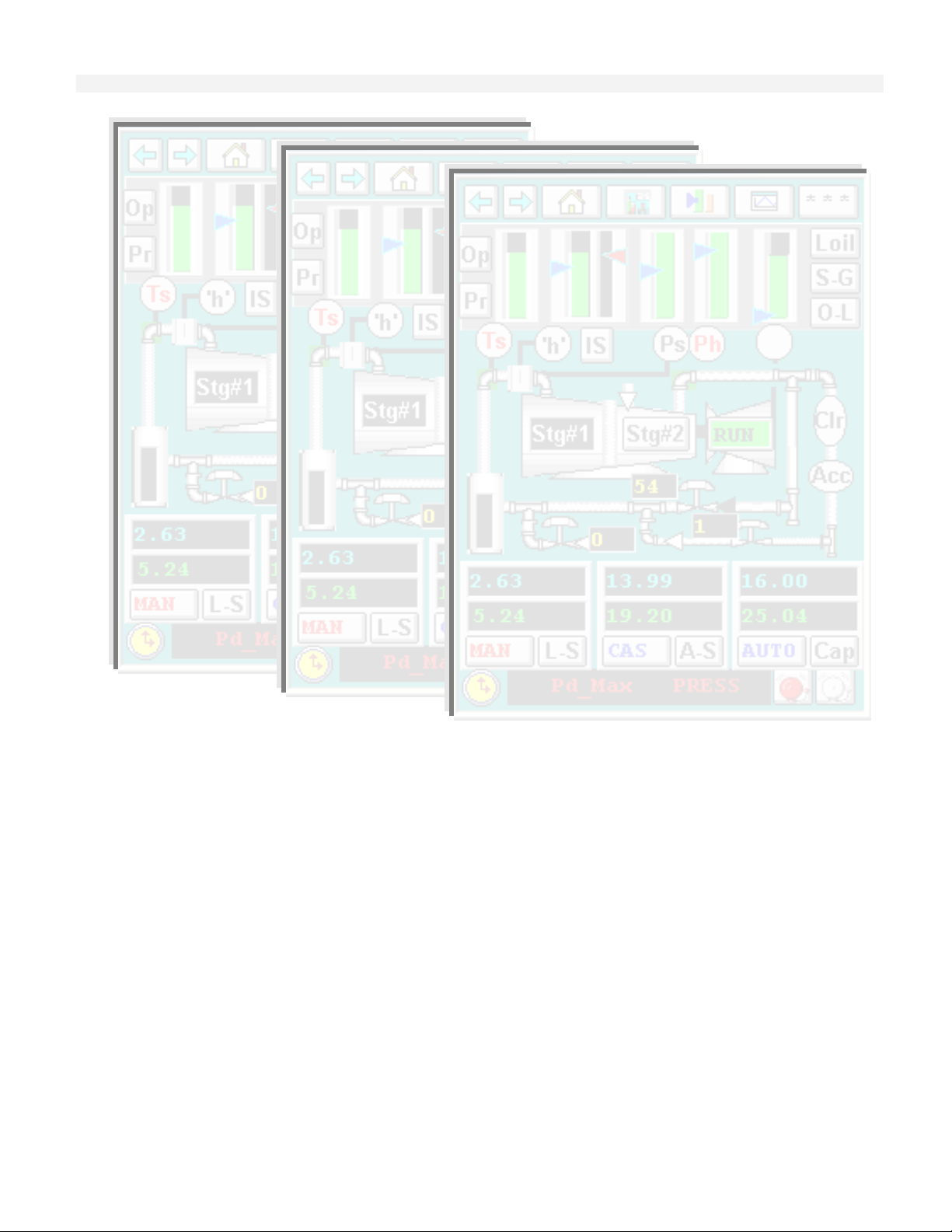
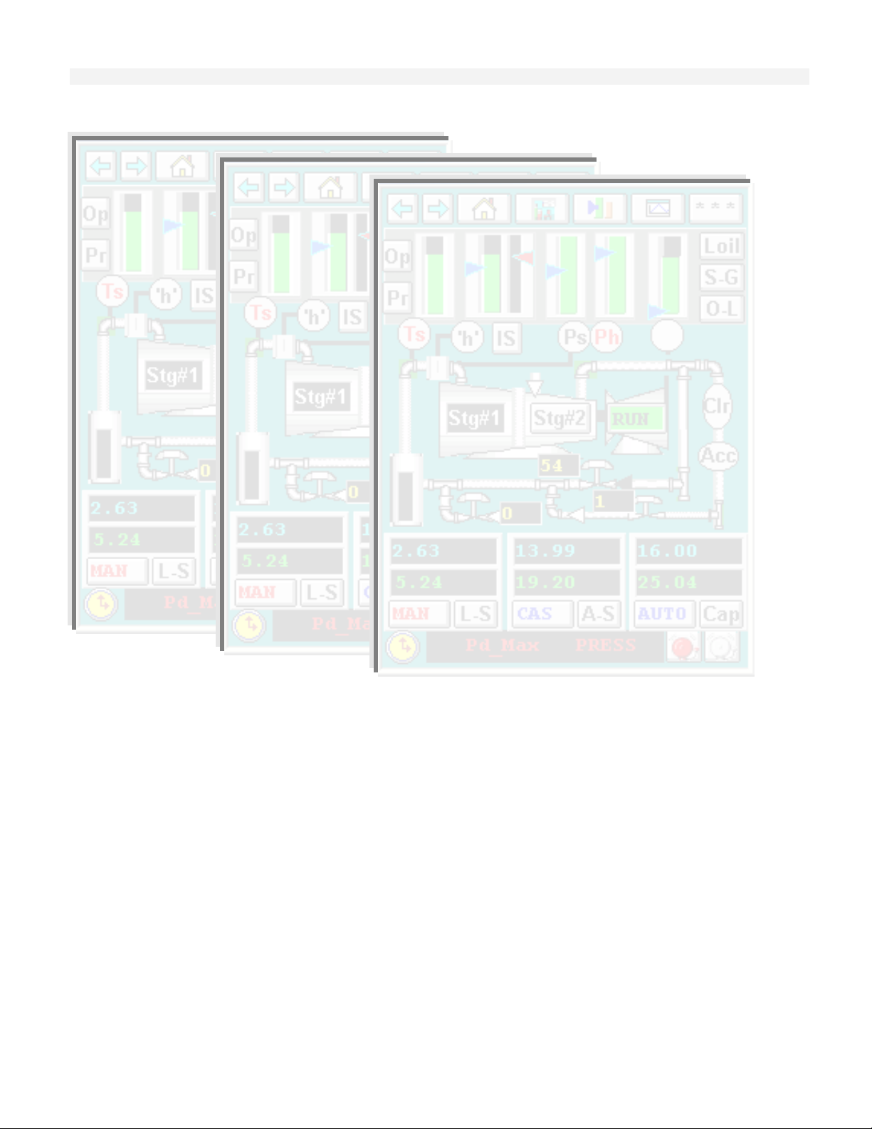
HMI Example – Single Stage Compressor.................... ...............................................................................6-22
Adaptation of Pre-Defined Displays ............................... .............................................................. .................6-25
Surge Curve Screens...................................................... ...............................................................................6-29
Custom Graphic Screens................................................ ...............................................................................6-30
Configuring the Security System.................................... ...............................................................................6-31
Communications.............................................................. ...............................................................................6-34
Downloading the Updated Application........................... ...............................................................................6-38
SECTION 7 – CONTROL PRIMER
Proportional (P) Action.................................................... ................................................................................7-4
Integral (I) Action… ......................................................... ................................................................................7-8
Derivative (D) Action ....................................................... ................................................................................7-8
Proportional-Plus-Integral (PI) Action……………………………………………………………………………7-9
Proportional-Plus-Derivative (PD) Action………………………………………………………………………..7-10
Proportional-Plus-Integral-Plus-Derivative (PID) Action………………………………………………………..7-11
Interactive and Non-Interactive Control………………………………………………………………………….7-12
Deadtime……………………………………………………………………………………………………………7-13
Cascade Control.............................................................. ................................................................................7-14
Ratio Control.................................................................... ................................................................................7-16
Damping........................................................................... ................................................................................7-16
4
Page 5

T6200
User’s Guide
SECTION 8 – CONFIGURATION
Preface............................................................................. ................................................................................8-3
Configuration Studio........................................................ ................................................................................8-4
Running the FBD Configurator Workbench................... ................................................................................8-4
Function Block Diagram (FBD) Editor............................ ...............................................................................8-10
Miscellaneous Workbench Features.............................. ...............................................................................8-16
Adaptation of Pre-Defined Configuration....................... ...............................................................................8-22
MICON OPC Server Start-up........................................................................................................................8-39
SECTION 9 – SPECIFICATIONS
APPENDIX A – DATA STRUCTURES AND EXPRESSIONS
Tags................................................................................. ................................................................................A-3
Reserved Words.............................................................. ................................................................................A-6
Labels............................................................................... ................................................................................A-7
Data Types ...................................................................... ................................................................................A-7
Logical Operations .......................................................... ................................................... .............................A-7
Arithmetic Operations...................................................... ................................................................................A-8
Relational Operations...................................................... ................................................................................A-8
Unary Operations............................................................ ................................................................................A-8
Expression....................................................................... ................................................................................A-9
Truth Tables..................................................................... ...............................................................................A-11
Logic Evaluation Rules ................................................... ...............................................................................A-11
Boolean Logic Rules ......................................................................................................................................A-11
APPENDIX B – MODBUS INTERFACE – RS-232
Preface............................................................................. ................................................................................B-2
T6200 MODBUS Functions Supported………………………………………………………………………….B-2
T6200 MODBUS Configuration…………………………………………………………………………………..B-3
5
Page 6

T6200
User’s Guide
6
Page 7
Product Overview
Section One
1
Product Overview
Design Structure 3
Analog and Discrete Input/Output 4
Line Power and Transmitter Power 5
System Security 5
On Line Diagnostics 6
Configuration Security 6
Controller Redundancy 6
Dual Non-Redundant Controller 6
1-1
Page 8
Product Overview
1-2
Page 9
Product Overview
PRODUCT OVERVIEW
The T6200 Controller is made up of two parts: The Operator Interface and the T6200 Controller.
The Operator Interface with the Windows CE platform enables complete interaction with the T6200
Controller. Through the touch screen and LCD display users can change setpoints, outputs, start/stop
devices, scroll through trends, or acknowledge alarms. The T6200 Controller functions as a
multiapplication Controller or intelligent RTU capable of performing all data acquisition, continuous
control, batch control, logic control and RTU requirements. Each T6200 Controller includes 999
function blocks in which control/logic functions can reside. The integral input/output (I/O) section
of each T6200 Controller accommodates 32 I/O points. The large library of functions (over 100) and
the practically unlimited number of blocks allow for pre-configuration of a wide variety of strategies
by the factory and permits field application optim izat ion.
Design Structure
The Operator Interface is an embedded PC. It is independent of the T6200 Controller and it
communicates with the T6200 Controller via Ethernet.
The T6200 Controller consists of three physical parts: the control board/s (single or redundant), the
controller housing, and the termination panel. Refer to Figure 1-1. The termination panel may also
include a remote termination panel for the I/O connections.
The control boards are a single printed circuit board design. The board contains the microprocessor
circuitry, the memory chips, the communication interfaces, and the input/output conditioning
components. Primary and backup control boards are identical.
1-3
Page 10
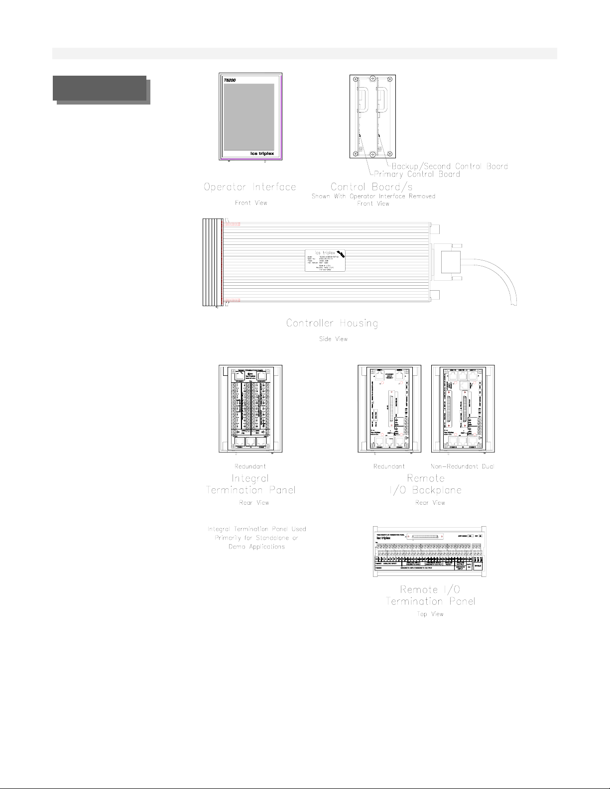
FIGURE 1-1.
T6200 Unit Controller
Product Overview
Analog and Discrete Input/Output
Analog inputs can be either current or voltage. High common mode (200 Volts) amplifiers are
utilized. Each input has a separate input amplifier. Also, each two wire transmitter input (4-20mA)
is provided with a separate internal 24 volt regulator. Analog outputs source up to 20 milliamperes
to the user’s receiver (load).
Most discrete inputs are opto-isolated (refer to specifications). The sample rate resolution of one
millisecond provides for first out sequence of events capability. Three of these inputs can be
1-4
Page 11

TABLE 1-1 .
TABLE 1-1.
Input/Output
Channel Assignments
Product Overview
configured as frequency/pulse inputs. Discrete outputs are transistor configurations. A separate
internal 24 volt regulator is supplied for each input/output.
The internal I/O section of the Controller accommodates 32 I/O points. Refer to Table 1-1 for I/O
channel assignment information.
I/O Channel Numbers
Type
T6200C
T6200D
1 - 8 9 – 16 17 - 22 23-26 27 - 30 31 - 32
Analog
Input
Analog
or
Discrete
Discrete
I/O *
Analog
I/O
Analog
Output
Discr
I/O*
Input
Discrete I/O
Discrete
Input
Discr
I/O*
* Channels 22, 31 and 32 can also be configured as a frequency/pulse input. C hannel 32 can also be
configured as a frequency/pulse output.
The process signals supported by the T6200 Controllers are:
• Analog Inputs (4-20 mA, ±20 mA, ±10 Vdc) internally or ext ernally powered
• Analog Outputs (4-20 mA, 0-20 mA)
Discrete Inputs (On-Off contacts) internally or externally powered
Discrete Outputs - internally or externally powered
Pulse Inputs (up to 25 kHz)
Line Power and Transmitter Power
The T6200 Controllers operate on 26 Vdc power. The T6200R subrack supplies redundant AC to
DC power supplies or the 26 Vdc can be obtained from any other reliable power source. Terminal
blocks are provided on the termination panel for primary and secondary (redundant) 26 Vdc power
input. Power for field transmitters, I/Ps, field switches, etc., is distributed through the T6200
Controller eliminating separate input/output power supplies and circuitry.
Both power supplies operate continuously. If one unit fails, it is not necessary to switch to the other
power supply. Both of the 26 Vdc sources are diode-isolated in the T6200 Controller to prevent the
failure of one from affecting the other. The supplies feed redundant power distribution traces on the
termination panel.
System Security
The Controller maximizes its reliability and availability by a design incorporating complete
redundancy of memory, intelligence, communication, and power. The redundancy includes total
process input/output circuitry backup. And, since each termination panel can accommodate both the
primary and backup control boards, the architecture allows for simple plug-in of the redundant
control board. No wiring or cabling is required for redunda nt confi gurati ons.
The integral backup communication link of each unit assures that both control boards (primary and
backup) maintain the same data base. Each control board has its own on-line, sophisticated
1-5
Page 12

diagnostics and also monitors the status of the other control board which provides for a reliable
transfer and redundancy scheme.
On Line Diagnostics
The T6200 Controller has on-line diagnostics designed to identify failures quickly. On all (primary
and backup) operator interfaces, highways, local communications, the Controller run diagnostics on
a continuous basis. These routines continuously check the status of critical device functi ons t o det ect
failures.
If a failure is detected an alarm is activated to inform the operator and the backup unit is enable d.
Configuration Security
The T6200 Controllers maintain identical configuration at all times. At startup, when both control
boards are powered up, the backup control board’s memory is always cleared, and the active control
board transfers the configuration to the backup control board through the backup serial link, if it has
a backup control board.
During operation (runtime), if new configuration is downloaded (to active control board), it
automatically goes to both the primary and the backup control board. Thus configuration integrity is
achieved and there are no mismatches.
Uninterrupted communication and control is provided by automatically transferring all configuration
and communications of the active control board to the backup redundant control board. There is a
complete transparency in the redundant control board. Apart from notification of failure, there is no
change in the operator interface.
Product Overview
Controller Redundancy
The T6200 Controller redundancy concept allows the user to simply plug-in a backup control board
side-by-side with the primary control board. The user has no installation or cable connection
requirements. Termination panel data links enable the backup to copy the input/output and control
configuration of the primary control board and to assume virtually immediately the input/output and
control functions in case of a primary malfunction.
Each control board contains, in addition to the input/output functions, an extensive library of control
algorithms. Thus, the T6200 Controllers can be configured as totally stand-alone intelligent
controllers or RTUs. This minimizes dependency on communications, resulting i n high reliabi lity.
Dual Non-Redundant Controller
The T6200 Dual Non-Redundant Controller concept allows the user to have two independent
controllers (a primary and a second controller) in one chassis thereby reducing the required panel
space by half. With this option, two T6200-C Controller cards or two T6200-D Controller cards or a
T6200-C and a T6200-D Controller card may be plugged into a single chassis. Two Rem ote I/O
Termination Panels (one for the primary controller and one for the second controller) are requi red
with this concept. The Dual Non-Redundant Controller option should onl y be used when c ontrol le r
redundancy is not foreseen as a requirement.
1-6
Page 13
Input/Output Circuit Description
Section Two
Analog Voltage Inputs 3
Analog Current Inputs 4
Analog Current Outputs 4
Isolated Discrete Inputs 6
Discrete Inputs with Excitation from Controller 6
Discrete Outputs 8
Discrete Outputs with Internal Power 8
Discrete Outputs with External Power 9
Active/Standby Logic 9
Input/Output Circuit Description
2
2-1
Page 14
Input/Output Circuit Description
2-2
Page 15
Input/Output Circuit Description
INPUT/OUTPUT CIRCUIT
DESCRIPTION
Each control board in the T6200 Controller incorporates the µP, memory, communicat ions and I/O
circuitry. Separate I/O modules are not required.
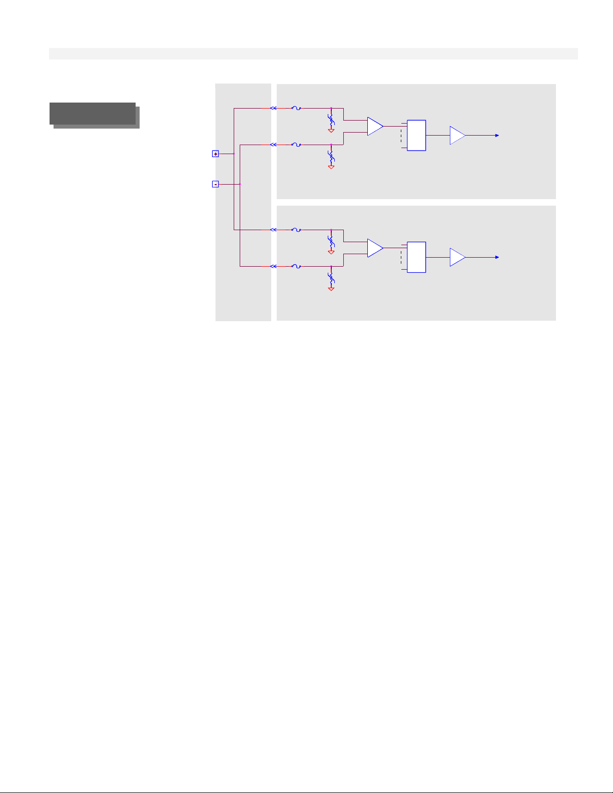
Analog Voltage Inputs
Up to 20 channels in the T6200-C Controller can be configured with field changeable jumpers for
voltage inputs. In reference to Figure 2-1, the input amplifier does not have galvanic isolation but it
appears to have it in most applications because of its high common-mode voltage and its high input
resistance. The 100 volt transient absorbers on each input will allow up to 100 volts dc or 75 volts
ac (rms, sine wave) continuously or up to 104 volts impulse voltage to enter the amplifier. The
amplifier will continue to operate with up to 200 volt s on it s inputs.
Each input has a separate input amplifier. The output of each of these amplifiers passes to the
analog switch. Only one of these inputs is selected at one time. The selected signal continues to the
programmable gain amplifier (PGA). The microprocessor selects the optimum gain setting for the
PGA. The possible input full scale ranges that can be selected are 0.625, 1.25, 2.5, 5, and 10 volts.
Inputs may be either polarity.
The voltage input configuration can be used as a current input by putting a resistor between the “+”
and “-” input terminals. Use a 250 ohm resistor for a 4 to 20 milliampere loop and a 100 ohm
resistor for a 10 to 50 milliampere loop.
2-3
Page 16
Input/Output Circuit Description
Primary Control Board
To ADC
FIGURE 2-1
Analog Voltage
Input
Analog
Voltage
Input
Termination
Panel
1A
100V
1A
100V
200 Volt
Common-mode
Amplifier
Analog
Switch
Programmable
Gain Amplifier
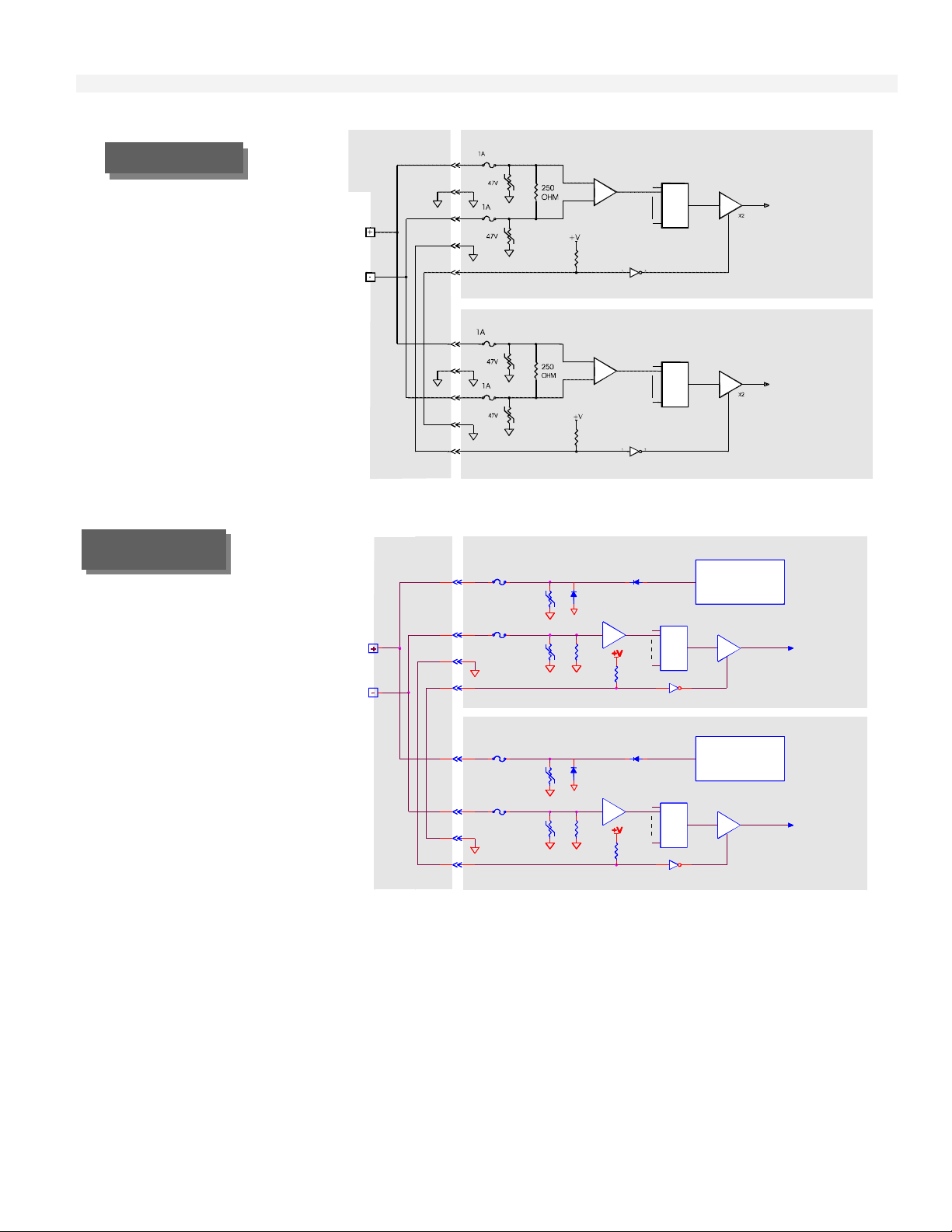
Analog Current Inputs
The current input is similar to the voltage input with 250 ohm resistor across the amplifier inputs. Field
changeable jumpers are used to select between voltage or current input. The maximum continuous input
current is 20 mA and 40 mA momentary. Refer to Figure 2-2. Also the gain is increased in the PGA by a
factor of two when a backup control board is present, to compensate for the decrease in voltage that the
additional 250 ohm resistor will cause.
When an isolated two-wire 4 to 20 milliampere transmitter is used, the circuit shown in Figure 2-3 m ay be
used. In this configuration a separate internal +24 volt voltage regulator is used for each transmitter. Each
voltage regulator has thermal, reverse voltage, and short-circuit protection. In this arrangement, one end
of the 250 ohm resistor is connected to circuit common. The two-wire 4-20 mA represents the standard
analog input jumper selection.
1A
100V
1A
100V
200 Volt
Common-mode
Amplifier
Analog
Switch
Programmable
Gain Amplifier
Backup Control Board
To ADC
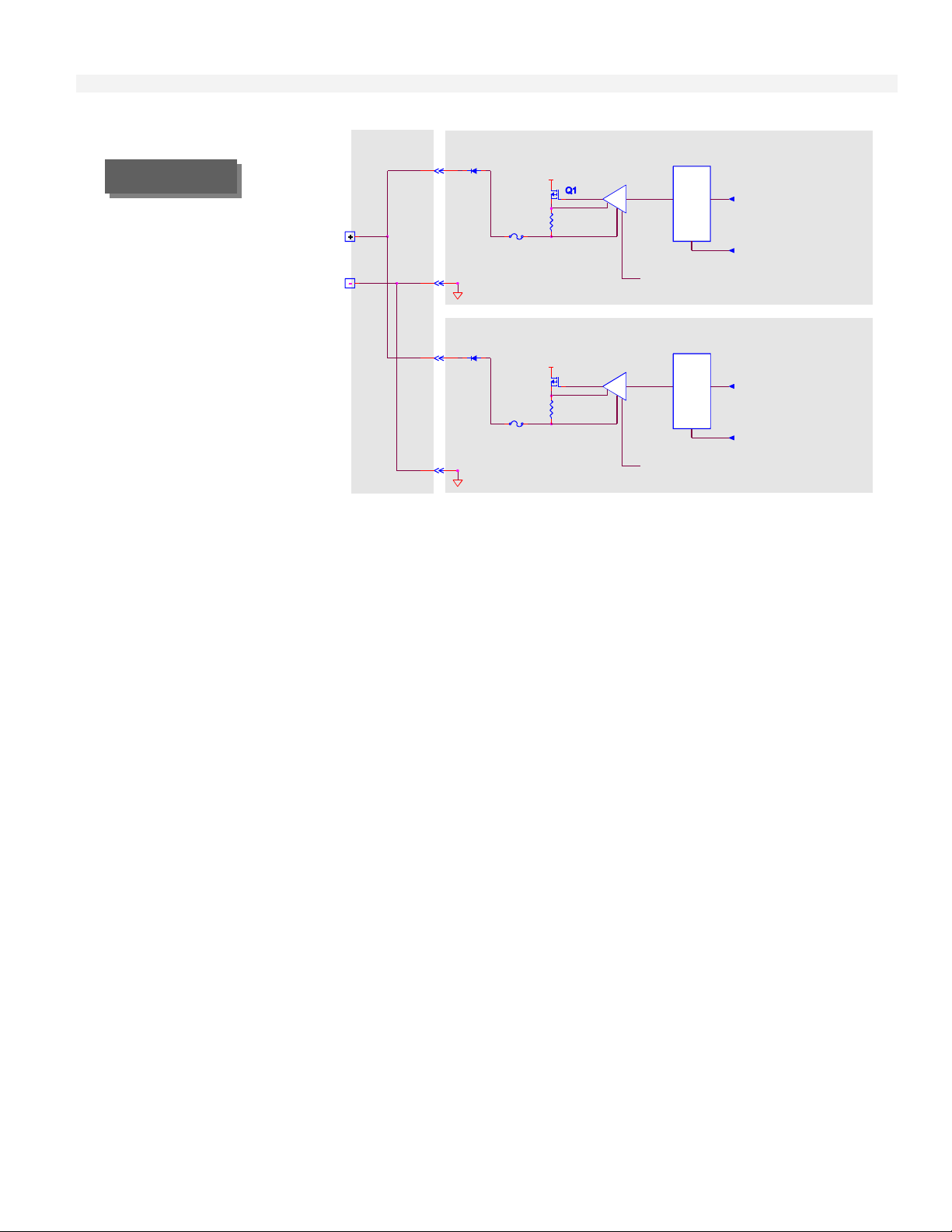
Analog Current Outputs
The T6200 Controller can be configured from four to eight current out put s. The current out put will source
from 0 to 20 milliamperes to the user's receiver (load). The receiver must share the same circuit common
as the T6200 Controller. The maximum receiver resistance is 1000 ohms.
In reference to Figure 2-4, the digital to analog converter (DAC) receives a digital value from the
microprocessor and converts it to an analog voltage. The voltage to the current converter, combined with
transistor Q1 and the 50 ohm resistor, converts the voltage to a current signal.
The output of the primary and backup control boards are connected together on the Controller termination
panel. The output is only enabled in the active control board. The diode is used to block the current from
the active control board.
2-4
Page 17
Input/Output Circuit Description
FIGURE 2- 2
Analog Current
Input
4-20 MA
Input
Termination
Panel
200 Volt
Common-mode
Amplifier
Analog
Switch
Primary Control Board
Program mable
Gain Amplifier
To AD C
FIGURE 2- 3
Two-Wire
Transmitter Input
200 Volt
Common-mode
Amplifier
Analog
Switch
Backup Control Board
Program mable
Gain Amplifier
To AD C
Primary Control Board
Voltage
Regulator with
short-circuit
protection
Programmable
Gain Amplifier
X2
Backup Control Board
Voltage
Regulator with
short-circuit
protection
Gain Amplifier
X2
To ADC
To ADC
Two-Wire
Transmitter
Input
Termination
Panel
1A
100V
1A
100V
1A
100V
1A
100V
24 VDC
250
OHM
24 VDC
250
OHM
Analog
Switch
Analog
Switch Programmable
+V
2-5
Page 18
Input/Output Circuit Description
FIGURE 2-4.
Analog Current
Output
Analog
Current
Output
Termination
Panel
125mA
125mA
+25.2V
+25.2V
50
OHM
50
OHM
Voltag e to
Current
Converter
DAC
Reset
Active from Figure 2-9
Voltag e to
Current
Converter
Q1
DAC
Reset
Active from Figure 2-9
Primary Control Board
From
Microprocessor
Inhibit from Figure 2-9
Primary Control Board
From
Microprocessor
Inhibit from Figure 2-9
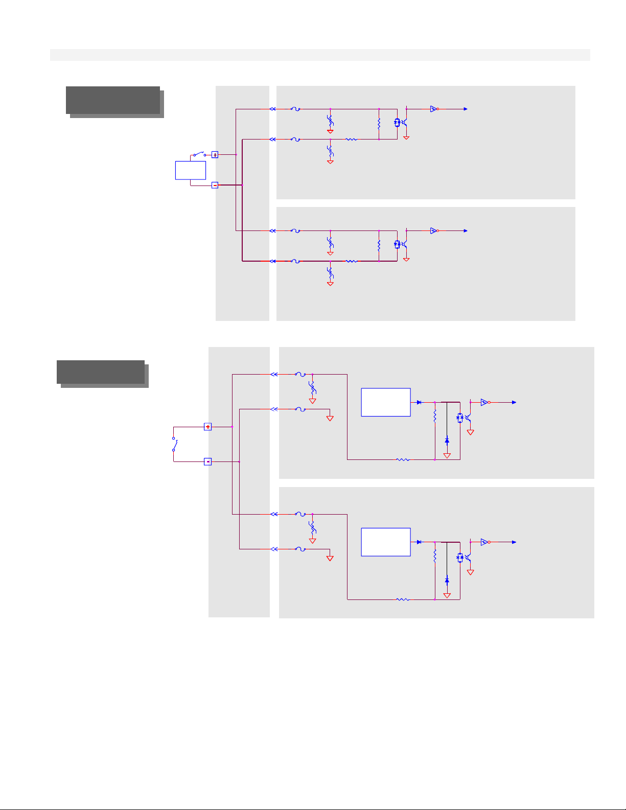
Isolated Discrete Inputs
The T6200-C Controller can be configured for up to 16 isolated discrete inputs. The T6200-D Controller
can be configured for up to 28 isolated discrete inputs in addition to the four internally power discrete
inputs. The resistor, in series with the input, is used to limit the maximum current to less than 6.5
milliamperes. In reference to Figure 2-5, the resistor across the opto-isolator is used to increase the
minimum input current to greater than one milliampere.
The opto-isolator provides electrical isolation between inputs and other circuits. Each input is protected
with fuses. A 100 volt transient absorber is provided on each input terminal to prevent arcing between
conductors on the circuit board. The maximum voltage that can be applied continuously is 38 volts dc or
30 volts ac (rms, sine wave). Discrete input channels 22, 31, and 32 can be used as frequency inputs, with
input frequencies up to 25 kHz. Other discrete inputs can be used as frequency inputs with input
frequencies up to 500 Hz.
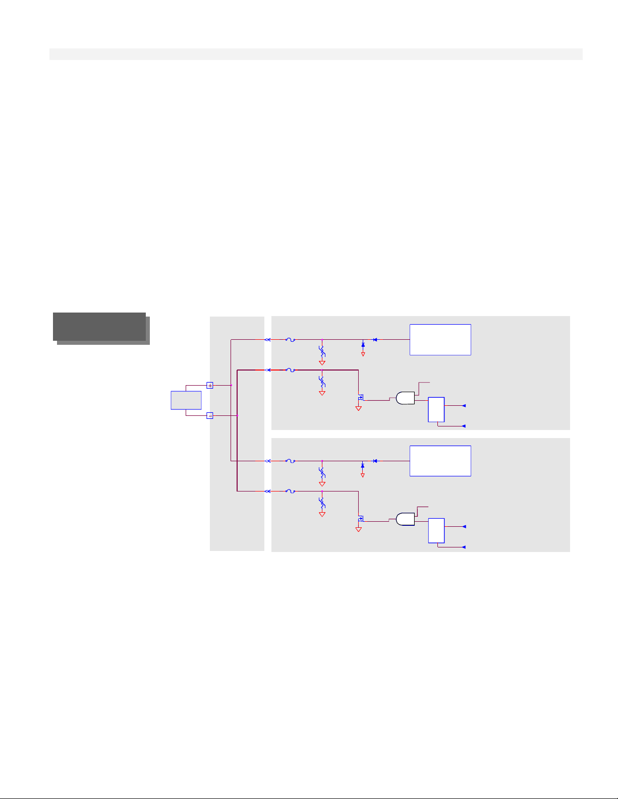
Discrete Inputs with Excitation from Controller
The discrete input is similar to the isolated discrete input above, without the isolation. The input is
internally powered. In this configuration a separate internal +24 volt regulator is provided for each dry
contact input. Each voltage regulator has thermal, reverse voltage, and short circuit protection. The
regulator supplies up to five milliamperes.
A contact closure between + and – terminals will activate the input. Refer to Figure 2-6. The internally
powered discrete input represents the standard discrete input jumper selection. The T6200 Controller has
a minimum of four internally powered discrete inputs.
2-6
Page 19
Input/Output Circuit Description
FIGURE 2- 5.
Isolated Discrete
Input
Power
Termination
Panel
1A
100V
1A
100V
1A
100V
1A
100V
1.8K
4.7K
1.8K
4.7K
Primary Control Board
Input to
Microprocessor
Backup ControlBoard
Input to
Microprocessor
FIGURE 2-6.
Discrete Input with
Excitation from
Controller
Termination
Panel
1A
100V
1A
1A
100V
1A
Voltage
Regulator
Voltage
Regulator
24 VDC
1.8K
4.7K
24 VDC
1.8K
4.7K
Primary Control Board
Input to
Microprocessor
Backup Control Board
Input to
Microprocessor
2-7
Page 20
Input/Output Circuit Description
Discrete Outputs
The T6200-C Controller can be configured for up to eight discrete outputs. The T6200-D Controller can
be configured for up to 28 discrete outputs. A 100 volt transient absorber is connected on each terminal to
protect the output transistor and to prevent arching between conductors on the circuit board. Each
terminal is protected with a one ampere fuse.
The output transistor in the standby (not ACTIVE) control board is alway s open.
Discrete output 32 can be used as frequency output, with output frequencies up to 10 kHz. Other discrete
outputs can be used as frequency outputs with output frequencies up to 100 Hz.
Discrete Outputs with Internal Power
In reference to Figure 2-7, a separate internal +24 volt voltage regulator is provided for each output. Each
voltage regulator has thermal, reverse voltage, and short-circuit protection. The regulator can supply 24
Vdc power for a load up to 20 milliamperes continuously and 100 mill iam peres momentarily .
FIGURE 2-7
Discrete
Output with
Internal Power
LOAD
<20 mA
Termination
Panel
1A
100V
1A
100V
24 VDC
Voltage
Regulator with
short-circuit
protection
Active from Figure 2-9
Latch
RS
Primary Control Board
Output from
Microprocessor
Inhibit from Figure 2-9
1A
100V
1A
100V
24 VDC
Voltage
Regulator with
short-circuit
protection
Active from Figure 2-9
Latch
RS
Backup Control Board
Output from
Microprocessor
Inhibit from Figure 2-9
2-8
Page 21
Input/Output Circuit Description
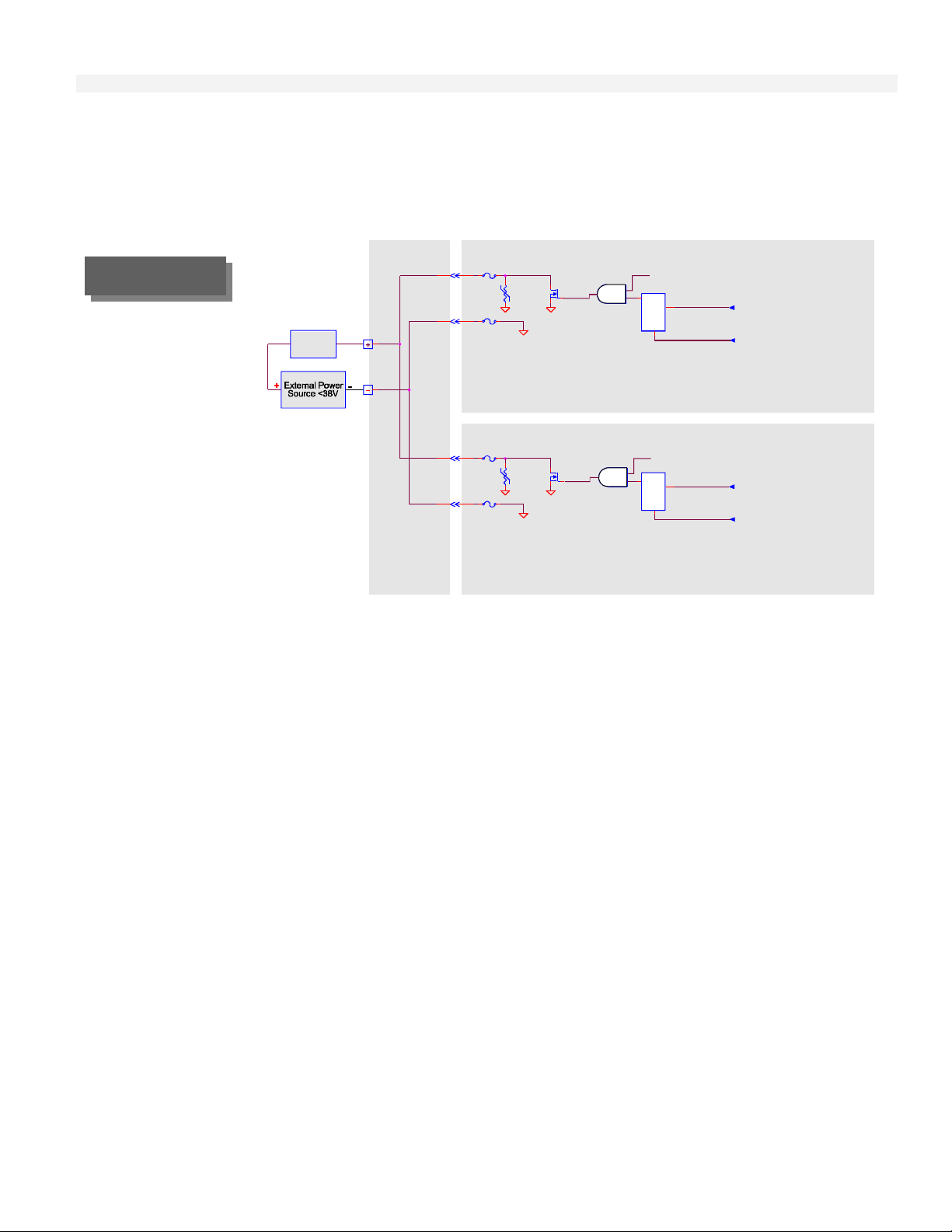
Discrete Outputs with External Power
In reference to Figure 2-8, the discrete transistor output with an external power source can sink up to 0.25
amperes continuously and one ampere momentarily. The maximum voltage that can be applied
continuously is 38 volts DC. The return (-) of the external power source must be connected to the “-”
input or “-” power terminal of the T6200 Controller.
Primary Control Board
Output fr om
Microprocessor
Inhibit from Figure 2-9
Backup Contr ol Board
Output fr om
Microprocessor
Inhibit from Figure 2-9
FIGURE 2-8.
Discrete Output
with External
Power
Load
<0.25A
T e rmination
Panel
1A
100V
1A
1A
100V
1A
Active from Figure 2-9
Latch
RS
Active from Figure 2-9
Latch
RS
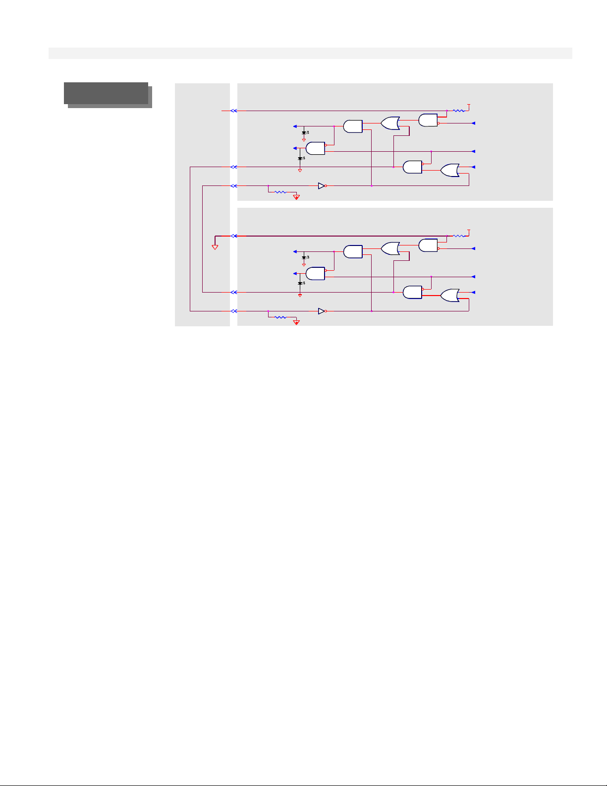
Active/Standby Logic
The active/standby logic determines which control board (primary or backup) is active and if the outputs
are active. Only one control board can assume the active role at any given time. Refer to Figure 2-9.
The inhibit signal is true when the control board is not active and the system fail signal is true. The inhibit
signal when true will reset the analog outputs to zero and reset the discrete output latches causing the
output transistors to open.
The only time the inhibit signal can be true, in a primary control board that does not have a good control
board in its backup position, is the first 0.2 second after power is first applied. This will allow the outputs
to reset on power up and to freeze the outputs if the system fail signal should become true when the
control board is active and must remain active.
2-9
Page 22
Input/Output Circuit Description
FIGURE 2-9
Termination
Panel
Primary Control B oard
Active/Standby
Logic
Active
Inhibit
Active
Inhibit
ACT
LED
OUT LED
ACT
LED
OUT LED
Power Up
Reset
System Fail
Activate
switch
Backup Control Board
Power Up
Reset
System Fail
Activate
switch
2-10
Page 23
Section Three
Site Selection Considerations 3
Access Considerations 3
T6200 Unit Automating System Mounting 4
T6200 Controller Electrical Power Wiring 6
T6200R Subrack Electrical Power Connection 8
Input/Output Hardware Configuration 9
Signal Wiring 10
Wiring and Jumper Placement for T6200-C Channels 1-8 12
Wiring and Jumper Placement for T6200-C Channels 9-16 13
Wiring and Jumper Placement for T6200-C Channels 17-22, 31, and 32 14
Wiring and Jumper Placement for T6200-C Channels 23-26 16
Wiring for T6200-C Channels 27-30 17
Wiring and Jumper Placement for T6200-D Channels 1-26, 31, and 32 17
Wiring for T6200-D Channels 27-30 19
Ethernet Communication Network 19
Network Security 19
Ethernet Network Connectors 19
Network Cabling 20
Non-Redundant Network 20
Redundant Network 21
T6200R Subrack Ethernet 23
Operator Interface Installation 24
Firmware Changes 27
Serial Communication Connection 28
Hardware Installation/Maintenance
Hardware Installation/Maintenance
3
3-1
Page 24
Hardware Installation/Maintenance
3-2
Page 25
Hardware Installation/Maintenance
Hardware
Installation/Maintenance
`
Site Selection Considerations
The T6200 Controller requires following conditions during normal operation:
32 to 122º F (0 to 50º C)
5 to 96% Relative humidity
Protection from direct contact with water, chemicals, and conductive dust.
Protection from exposure to sulfur compounds, acid, other corrosive or reactive vapors or
fumes, dust, and lint.
For estimating heat load requirements, the T6200 Controller dissipates a maximum of 10 BTU/hr.
(or 24 KGM-CAL/Hr) to the inside of the control panel.
Access Considerations
There are very few restrictions on the mounting position of the T6200 Controller. The following should
be taken into consideration:
All electrical power and input/outputs are connected on the rear termination panel.
Because as many as 70 conductors and four cables can be terminated to each T6200 Controller
adequate wireway space should be provided.
The T6200 Controller is operated from the front of the unit with switches on the
bottom. The Operator Interface slides up 0.5 in. (12 mm) to remove.
3-3
Page 26

The control boards slide out the front of the unit.
To ensure a proper viewing angle, the Controller should be installed approximately
64 inches (1.6 m) above the floor.
Outdoor installation is not recommended. However, for outdoor installations, the
face of the Controller should be shielded from direct sunlight, since bright light produces a
poor display contrast.
T6200 Controller Mounting
T6200 Controller Mounting
Figure 3-1 provides mounting dimensions for the T6200 Controller. Dimensions are shown in inches
(mm).
Remove Operator Interface by pushing up and pulling out at the bottom. Disconnect cable
from Operator Interface
Use the two Phillips head screws and clamps to mount the T6200 Controller in the user’s
panel.
When the T6200 Controller is positioned properly, hand-tighten both clamps in place. Note:
Do not exceed 15 in-lbs (17 cm-kgs) of torque on panel clamp screws.
The panel cut-out dimensions, as well as the Operator Interface front outline dimensions are shown in
Figure 3-2. The T6200 Controller would normally be mounted in a vertical posit ion.
Figure 3-3 provides mounting dimensions for the optional Remote I/O Termination Panel. The I/O
cable that connects the T6200 Controller to the Remote I/O Termination Panel is 6 ft. (2m) long.
Dimensions are shown in inches (mm). The Remote I/O Termination Panel can be snapped onto a user
supplied standard 35 mm DIN rail.
T6200R Subrack Mounting
Each T6200R Subrack Housing accommodates up to six redundant T6200 Controllers. The subrack
may also include two power supplies, Operator Interface, and two Ethernet hubs. Refer to Figure 3-4
for T6200R Subrack mounting dimensions. The subrack should be mounted in a EIA standard 19 inch
rack. Refer to Section Nine Specifications for more detailed physical dimensions.
Hardware Installation/Maintenance
3-4
Page 27
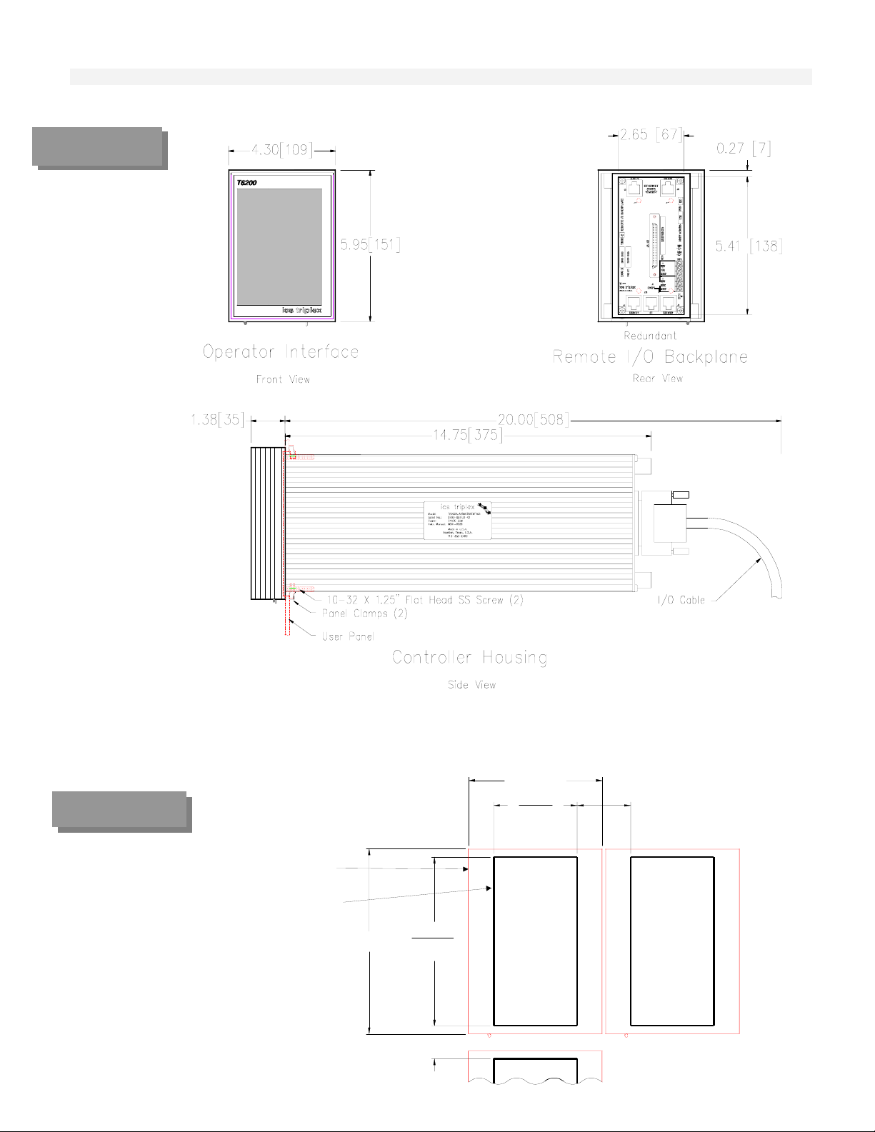
FIGURE 3-1.
T6200
Mounting
Hardware Installation/Maintenance
FIGURE 3-2.
T6200 Controller
Panel Cutout
Dimensions
OPERATOR INTERFACE
PANE L CU TO U T
5.95 [151]
5.44 [138]
5.50 [139]
1.375 [35]
4.30 [109]
2.74 [69]
2.68 [68]
1.72 [44] MIN
3-5
Page 28
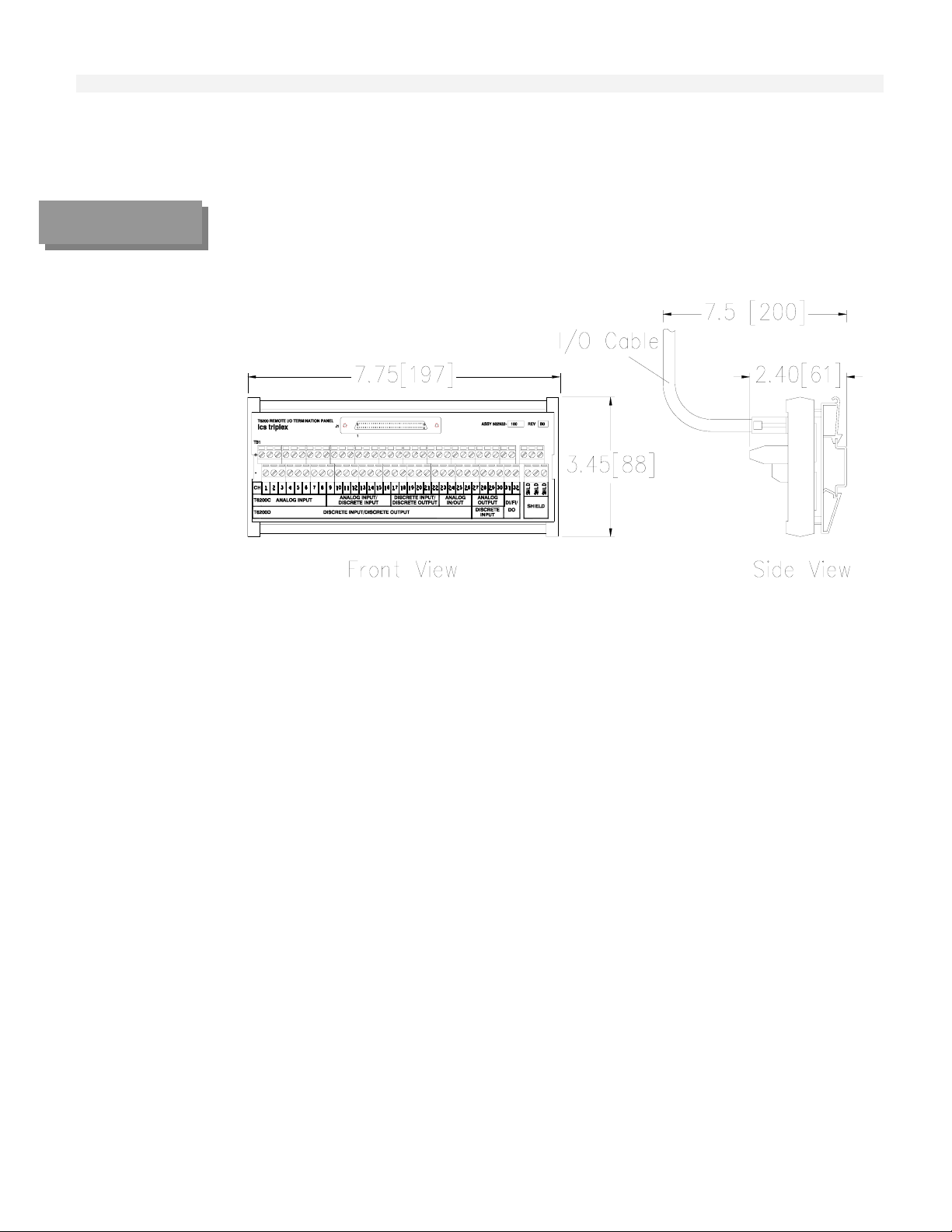
FIGURE 3-3
Remote I/O
Terminal Panel
Mounting
Dimensions
Hardware Installation/Maintenance
T6200 Controller Electrical Power Wiring
The guidelines below should be followed when wiring the power to the T6200 Controlle r:
The maximum wire size is 16 AWG stranded.
All wiring should be multi-stranded annealed copper with insulation that meets the
requirements of all applicable electrical codes.
AC power wiring should be run in a separate conduit from the T6200 Controller power and the
I/O.
The stripped portion of the wire should be 3/16” (5 mm) long.
Wires should be inserted in the clamp type terminals until they touch the internal stops. The
terminal screw should be tightened while holding the wire in place. Check for proper clamp
pressure with a gentle tug on the wire.
Electrical power should be provided from a redundant, highly reliable, dedicat ed 26 Vdc power
source.
Power consumption is 15 watts for the T6200 Controller and 15 watts for the Operator
Interface, not including field devices.
The T6200 Controller has redundant 26 Vdc power supply connections.
3-6
Page 29
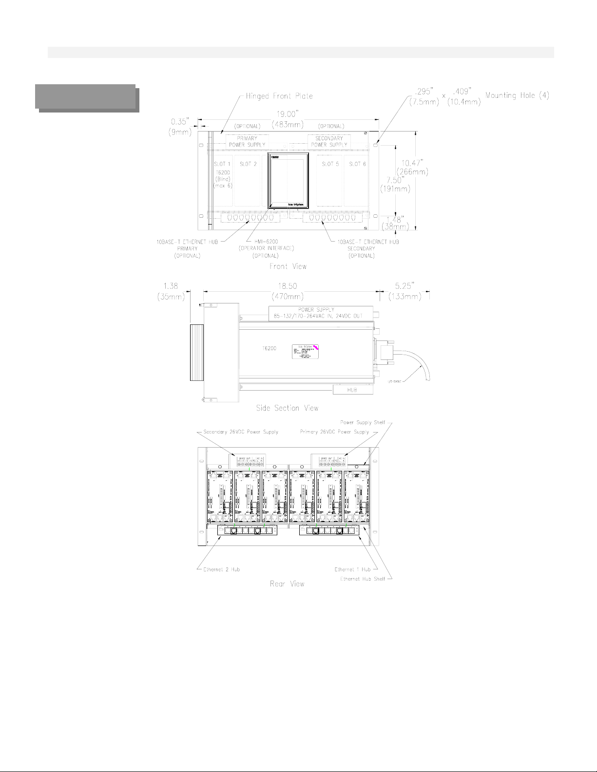
FIGURE 3-4
T6200R Subrack
Mounting
Dimensions
Hardware Installation/Maintenance
Figure 3-5 shows the internal power distribution for the T6200 Unit Automation System. Connect 26
Vdc (18-32 Vdc) power to the 26V PRI (Primary) terminals and to the 26V SEC (Secondary)
terminals.
There is a jumper (W1) on the T6200 Termination Panel that connects the minus side of the 26 volt
supply to earth ground. This jumper may be cut if the power source is referenced to earth ground
somewhere else in the system.
3-7
Page 30
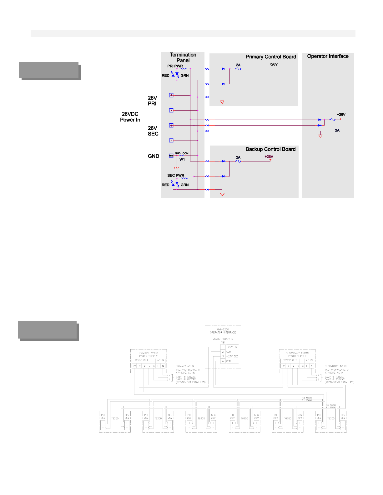
FIGURE 3-5
Internal Power
Distribution
Hardware Installation/Maintenance
T6200R Subrack Electrical Power Connection
Once the T6200R Subrack is mounted, plug the included external power supply’s DC power cord into
the matching power jack on each of the Ethernet Hub’s rear panel. The Ethernet Hub shelf may be
removed to connect the power. Plug each of the power supply’s transformers into an AC receptacle that
is six feet (two meters) or less away. The green “Pwr” LED should light up.
Refer to the guidelines in T6200 Controller Electrical Power Wiring above and Figure
3-6 and connect AC power wiring to each of the 26 Vdc Power Supplies.
The 26 Vdc power to the T6200 Controllers and Operator Interface is usually prewired as shown in
Figure 3-6.
Figure 3-6
T6200R Subrack
Power Wiring
3-8
Page 31

Input/Output Hardware Configuration
There are several different ways the hardware can be configured for each input/output. Refer to
Section Two Input/Output Circuit Description for details on each configuration. The different
configurations are achieved by the placement of jumpers (shorting bars) on a multi-pin headers located
on the printed circuit board. Each channel has a separate header and can be configured independently.
To access the jumpers:
CAUTION
Unplug the optional front panel Operator Interface
Carefully slide the printed circuit board out the front of the chassis.
The Controller contains parts susceptible to damage by electrostatic
discharge. Normal precautions should be taken to avoid high static
voltages.
When facing the component side of the printed circuit board with the LEDs on the left, the
headers/jumpers will be at the right Pin one on the headers will be as shown in the illustrations. Pin one
also has a square pad on the circuit side of the printed circuit board. Refer to Figure 3-7 for T6200C.
Refer to Figure 3-11 for T6200D.
Hardware Installation/Maintenance
FIGURE 3-7.
T6200C Control
Board
The headers may vary from input/output group to group. All the headers are oriented the same way
within one group. A group is where a`ll consecutive inputs/outputs have the same configuration
options. For example, channels one through eight are in the same group.
3-9
Page 32

Signal Wiring
FIGURE 3-8
Hardware Installation/Maintenance
Individually shielded wires are not required (except for frequency inputs). Twisted pairs and overall
cable shields are recommended. Each multipair cable should contain a few pairs of spare wires. Shiel ds
and unused conductors should be terminated to ground at Controller end only. Refer to appropriate
Wiring and Jumper Placement.
The following general guidelines apply to all signal wiring discussed in the following paragraphs.
Wire size range for the terminal panel is 26-16 AWG stranded; recommended wire size range
is 18-14 AWG.
Wire size range for the remote I/O terminal is 26-14 AWG stranded; recommended wire size
range is 18-14 AWG.
All wiring should be multi-stranded annealed copper with insulation that meets the
requirements of all applicable electrical codes.
Keep all wire runs as short and direct as possible. Long wire runs are vulnerable to picking up
stray electrical noise. Use care when running signal wiring near to or crossing conduit or
wiring that supplies power to motors, solenoids, lighting, horns, bells, et c.
Avoid bringing signal wiring into junction boxes which contain ot her wiri ng.
AC power wiring should be run in a separate conduit from the signal wiring.
The stripped portion of the wires should be 5/16” (8 mm) long.
Wires should be inserted in the clamp type terminals until they touch the internal stops. The
terminal screw should be tightened while holding the wire in place. Check for proper clamp
pressure with a gentle tug on the wire.
Integral
Termination
Panels
3-10
Page 33
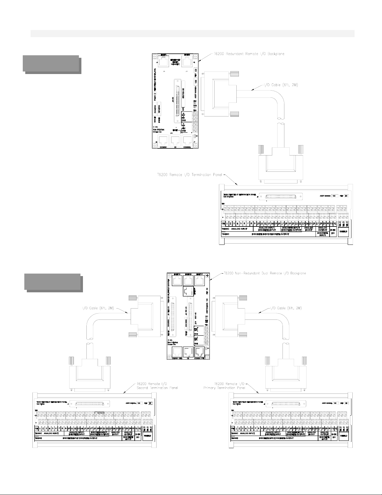
FIGURE 3-9
Redundant
Remote I/O
Termination
Panel
Hardware Installation/Maintenance
FIGURE 3-10
Dual
Non-Redundant
Remote I/O
Termination
Panel
3-11
Page 34

Wiring and Jumper Placement for T6200C
Channels 1-8
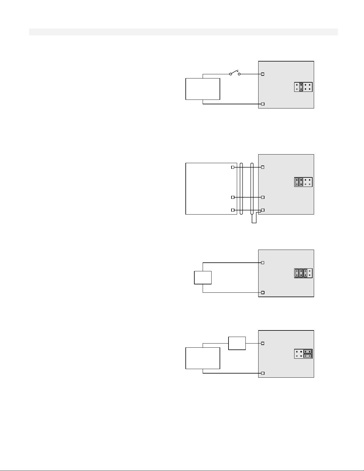
Two-Wire Transmitter
This wiring and jumper
placement is normally used
with isolated two-wire
transmitters where the
transmitter power is
supplied by the Controller.
Refer to Figure 2-3.
Analog Current Inputs
This wiring and jumper
placement is normally used
with four-wire current
transmitters when the power
is not
supplied by the
Power
Source
Controller. Refer to Figure
2-2.
Analog Voltage Inputs
This wiring and jumper
placement is for voltage
inputs. Refer to Figure 2-1.
Power
Source
+
4-20 mA
Two-Wire
Transmitter
(Isolated)
-
+
4-20 mA
Transmitter
-
Transmitter output
may be referenced
to common
+
DC Voltage
Transmitter
-
Transmitter output
may be referenced
to common
Hardware Installation/Maintenance
T6200C Controller
24 Vdc
+
Supply
mA Input
(reference to
-
common
through resistor)
SHLD
T6200C Controller
+
mA Input
(Isolated from
common)
-
SHLD
T6200C Controller
+
DC Voltage Input
(Isolated from
common)
-
SHLD
1
Factory
Default
1
1
3-12
Page 35

Wiring and Jumper Placement for T6200C
Channels 9-16
Two-Wire Transmitter
Hardware Installation/Maintenance
This wiring and jumper
placement is normally used
with isolated two-wire
transmitters where the
transmitter power is
supplied by the Controller.
Refer to Figure 2-3.
Analog Current Input
This wiring and jumper
placement is normally used
with four-wire current
transmitters when the power
is not
supplied by the
Controller. Refer to Figure
2-2.
Analog Voltage Input
This wiring and jumper
placement is for voltage
inputs. Refer to Figure 2-1.
Power
Source
Power
Source
+
4-20 mA
Two-Wire
Transmitter
(Isolated)
-
+
4-20 mA
Transmitter
-
Transmitter output
may be referenced
to common
+
DC Voltage
Transmitter
-
Transmitter output
may be referenced
to common
T6200C Controller
24 Vdc
+
Supply
mA Input
(reference to
-
common
through resistor)
SHLD
T6200C Controller
+
mA Input
(Isolated from
common)
-
SHLD
T6200C Controller
+
DC Voltage Input
(Isolated from
common)
-
SHLD
1
Factory
Default
1
1
3-13
Page 36

Hardware Installation/Maintenance
Discrete Inputs with Excitation from Controller
This wiring and jumper
placement is for discrete
(On/Off) inputs. The
Controller supplies 24 VDC
power for the input. Refer to
Figure 2-6.
Alternate
Open Collector
Transistor
Contact
T6200C Controller
Discrete Input
+
(24 Vdc/5 mA
excitation)
Circuit
-
Common
1
Isolated Discrete Inputs
This wiring and jumper
placement is for discrete
(On/Off) inputs. The
discrete inputs are isolated
from other circuits and the
external power for the input
Power Source
18 V to 32 V
ac/dc
Contact
Polarity
Arbitrary
is either 18-32 Volt AC or
DC. Refer to Figure 2-5.
T6200C Controller
+
+
Discrete Input
(Optically
coupled)
-
-
1
Wiring and Jumper Placement for T6200C
Channels 17-22, 31, and 32
Discrete Inputs with Excitation from Controller
This wiring and jumper
placement is for discrete
(On/Off) inputs. The
Controller supplies 24
VDC power for the input.
Refer to Figure 2-6.
Isolated Discrete Inputs
This wiring and jumper
placement is for discrete
(On/Off) inputs. The
discrete inputs are isolated
from other circuits and the
external power for the
input is either 18-32 Volt
AC or DC. Refer to
Figure 2-5.
Power Source
18 V to 32 V
Open Collector
ac/dc
Alternate
Transistor
Contact
Polarity
Arbitrary
Contact
T6200C Controller
Discrete Input
+
(24 Vdc/5 mA
excitation)
Circuit
-
Common
T6200C Controller
+
+
Discrete Input
(Optically
coupled)
-
-
1
Factory
Default
1
3-14
Page 37

Hardware Installation/Maintenance
Frequency Inputs
This wiring and jumper
placement is for a
PWR
frequency/pulse
preamplifier input with
the Controller supplying
the power (Channel 22,31
and 32).
Frequency/Pulse
Preamplifier or other
Discrete Device
0-25KHz only for
Channels 22, 31 &
32
OUT
COM
Discrete Outputs with Internal Power
This wiring and jumper
placement is for discrete
(On/Off) outputs. The
Controller supplies 24
VDC power for the 20
mA max load. Load
Example: Entrelec RB
+
Discrete
Load
<20 mA
-
131 (010055.23) relay.
Refer to Figure 2-7.
Discrete Outputs with External Power
T6200C Controller
24 Vdc
+
Supply
1
Input
(Circuit Common)
-
SHLD
Discrete
T6200C Controller
24 Vdc
+
+
Supply
Discrete Output
(Open Collector
-
-
Transistor)
1
This wiring and jumper
placement is for discrete
(On/Off) outputs. The
power source (less than 38
VDC) is external. The
discrete load is 0.25 Amp
max. Refer to Figure 2-8.
+
Power Source
<38 Vdc
-
Discrete
+-
Load
<0.25 A
T6200C Controller
Discrete Output
+-+
(Open Collector
Transistor)
Circuit
Common
1
3-15
Page 38

Wiring and Jumper Placement for T6200C
Channels 23-26
Two-Wire Transmitter
Hardware Installation/Maintenance
This wiring and jumper
placement is normally
used with isolated
two-wire transmitters
where the transmitter
power is supplied by the
Controller. Refer to
Figure 2-3.
+
4-20 mA
Two-Wire
Transmitter
(Isolated)
-
T6200C Controller
24 Vdc
+
Supply
mA Input
(reference to
-
common
through resistor)
SHLD
1
Factory
Default
Current Inputs
This wiring and jumper
placement is normally
used with four-wire
current transmitters when
the power is not
supplied
by the Controller. Refer
to Figure 2-2.
Power
Source
+
4-20 mA
Transmitter
-
Transmitter output
may be referenced
to common
T6200C Controller
+
mA Input
(Isolated from
common)
-
SHLD
1
Analog Voltage Inputs
This wiring and jumper
placement is used for
voltage input. Refer to
Figure 2-1.
Power
Source
+
DC Voltage
Transmitter
-
Transmitter output
may be referenced
to common
T6200C Controller
+
DC Voltage Input
(Isolated from
common)
-
SHLD
1
Analog Current Outputs
0-20mA (4-20mA)
Analog current outputs.
Refer to Figure 2-4.
+
4-20 mA or
0-20 mA
Receiver
(Isolated)
-
T6200C Controller
+-mA Output
Circuit
Common
1
SHLD
3-16
Page 39

Wiring for T6200C
Channels 27-30
Analog Current Outputs
Hardware Installation/Maintenance
FIGURE 3-11
T6200D Control
Board
0-20mA (4-20mA)
Analog current outputs.
Refer to Figure 2-4.
Channels 27-30 do not
have jumper placements.
+
4-20 mA or
0-20 mA
Receiver
(Isolated)
-
T6200C Controller
+-mA Output
Circuit
Common
SHLD
Wiring and Jumper Placement for T6200D
Channels 1-26, 31, and 32
Discrete Input with Excitation from Controller
This wiring and jumper
placement is for discrete
(On/Off) inputs. The
Controller supplies 24
VDC power for the input.
Refer to Figure 2-6.
Alternate
Open Collector
Transistor
Contact
T6200D Controller
Discrete Input
+
(24 Vdc/5 mA
excitation)
Circuit
-
Common
1
Factory
Default
3-17
Page 40
Hardware Installation/Maintenance
Isolated Discrete Input
This wiring and jumper
placement is for discrete
(On/Off) inputs. The
discrete inputs are isolated
from other circuits and the
external power for the
input is either 18-32 Volt
AC or DC. Refer to
Figure 2-5.
Power Source
18 V to 32 V
ac/dc
Contact
Polarity
Arbitrary
T6200D Controller
+
+
Discrete Input
(Optically
coupled)
-
-
1
1
Frequency Input
This wiring and jumper
placement is for a
PWR
frequency/pulse
preamplifier input with
the Controller supplying
the power (Channel 22,31
and 32).
Frequency/Pulse
Preamplifier or other
Discrete Device
0-25KHz only for
Channels 22, 31 &
32
OUT
COM
Discrete Output with Internal Power
This wiring and jumper
placement is for discrete
(On/Off) outputs. The
Controller supplies 24
VDC power for the 20
mA max load. Load
example: Entrelec RB 131
+
Discrete
Load
<20 mA
-
(010055.23) relay Refer to
Figure 2-7.
Discrete Outputs with External Power
This wiring and jumper
placement is for discrete
(On/Off) outputs. The
power source (less than 38
Vdc) is external. The
discrete load is 0.25 Amp
max. Refer to Figure 2-8.
+
Power Source
<38 Vdc
-
Discrete
+-
Load
<0.25 A
T6200D Controller
24 Vdc
+
Supply
Discrete
-
Input
(Circuit Common)
SHLD
T6200D Controller
24 Vdc
+
+
Supply
Discrete Output
(Open Collector
-
-
Transistor)
T6200D Controller
Discrete Output
+-+
(Open Collector
Transistor)
Circuit
Common
1
1
1
3-18
Page 41

Wiring for T6200D
Channels 27-30
Discrete Inputs with Excitation from
Controller
Hardware Installation/Maintenance
These channels are for
placement is for discrete
(On/Off) Inputs only. The
Controller supplies 24
VDC power for the input.
Refer to Figure 2-6
Channels 27-30 do not
have jumper placements.
Ethernet Communication Network
The T6200 Controller uses IEEE 802.3 10Base-T Ethernet communication network. Ethernet uses
the Carrier Sense, Multiple Access, Collision Detect (CSMA/CD) datalink protocol, which employs a
broadcast method for communicating with nodes. When a station senses that the network is idle and
it is ready to send, it transmits its data packets to the network. Since all nodes hear the data, each
node checks to see if the packet is intended for it. The station that matches the d estination address in
the packet is the one that responds. The collision detection part of CSMA/CD tells nodes to halt
transmission if a collision is detected and to try again later at a randomly determined delay period.
Network Security
The T6200 Controller incorporates automatic control redundancy to insure process equipment
operation in the event of failure. Redundant network components can further enhance overall system
security by maintaining communications in case of certain device malfunction and by allowing online
repair of faulty components. With proper redundancy implementation an Ethernet network can detect
when a particular path cannot pass data and then automatically switch to a backup path. Refer to
T6200 Equipment Selection and Planning G ui de for more information on network security.
Alternate
Open Collector
Transistor
Contact
T6200D Controller
Discrete Input
+
(24 Vdc/5 mA
excitation)
Circuit
-
Common
Ethernet Network Connectors
The T6200 Controller includes two individual IEEE 802.3 10Base-T Ethernet connections (ENET1 and
ENET2) with standard RJ-45 connectors to facilitate control network communication. Refer to Figure
3-8 (Integral Termination Panel), Figure 3-9 (Redundant Remote I/O Backplane) or Figure 3-10 (NonRedundant Dual Remote I/O Backplane) for connector location and Figure 3-12 for Ethernet ENET1
and ENET2 connector pin assignments.
Note on Figure 3-10 (Non-Redundant Dual Remote I/O Backplane) ENET1 on the Primary Control
Board is referenced as ENET1P and ENET2 is referenced as ENET2P. ENET1 on the Second Control
Board is referenced as ENET1S and ENET2 is referenced as ENET2S.
3-19
Page 42

FIGURE 3-12
Ethernet
ENET1 and ENET2
Connector
Pin Assignments
Network Cabling
Pin Signal
1 TXD+
2 TXD3 RXD+
4 NC
5 NC
6 RXD7 NC
8 NC
Ethernet is used as the high-speed wire media to provide the control network communication
capabilities for the T6200 Controller systems. Typically, the control network is an isolated Ethernet
network that provides communication between the T6200 Controller and workstations. It uses
Ethernet hubs and/or switches for communication connections.
Use Ethernet category five (Cat 5) cables for the Ethernet network cables. The maximum cable
length from the T6200 Controller to the hub/switch is 10 ft. (3 m). The maximum cable length from
the hub/switch to any other node is 330 ft. (100 m) for longer distances, fiber optic cables are
required.
Pin 1
Hardware Installation/Maintenance
Pin 8
Non-Redundant Network
The basic simplex network consists of a hub and Cat 5 cables that connect to each node. The T6200
Controllers have redundant Ethernet ports as a standard feature (whether they contain simplex or
redundant control boards). When installing a simplex network, using Ethernet 2 port is optional.
Refer to Figure 3-13 for a single T6200 Controller and Figure 3-14 for multiple T6200 Controllers.
FIGURE 3-13
Non-Redundant
Network with
Single T6200
Controller and
Single
Workstation
3-20
Page 43

FIGURE 3-14
Non-Redundant
Network with
Multiple T6200
Controllers and
Dual
Workstations
Hardware Installation/Maintenance
Redundant Network
Network redundancy for communication security is provided by a secondary hub and cables that
establish a secondary network identical to the primary netw ork. The secondary n etwork is connected
to the redundant communications port of each workstation and Controller, and is connected to a
separate hub/switch. Refer to Figure 3-15.
FIGURE 3-15
Redundant
Network with
Single T6200
Controller and
Redundant
Workstations
3-21
Page 44

FIGURE 3-16
Redundant
Network with
Multiple T6200
Controllers and
Redundant
Workstations
Hardware Installation/Maintenance
FIGURE 3-17
Redundant
Network with
Multiple T6200
Controllers
Mounted in a
T6200R Subrack
and
Redundant
Workstations
3-22
Page 45

FIGURE 3-18
Non-Redundant
Network with
Single Dual T6200
Controller and
Single
Workstation
Hardware Installation/Maintenance
FIGURE 3-19
Redundant
Network with
Multiple
Dual T6200
Controller and
Redundant
Workstations
T6200R Subrack Ethernet
The Ethernet Hubs on the T6200R Subrack are usually connected as shown in Figure 3-17.
If the workstation is not part of an existing network, connect the workstation to port eight on the
hubs. Set the Up-Link switch to “Normal”.
To connect the hubs to an existing network; set the Up-Link switch to “Up-Link” and connect
existing network to port eight.
The Operator Interface is usually connected to port seven on Ethernet 1 Hub.
3-23
Page 46
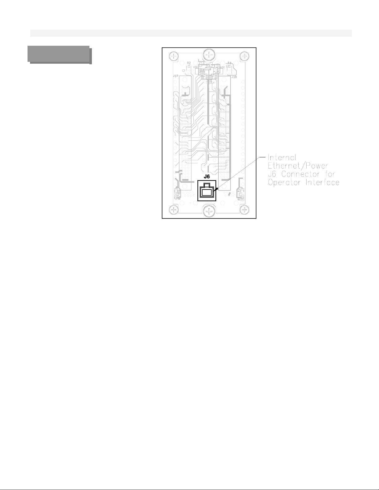
p
FIGURE 3-20
Internal
Ethernet/Power
J6 Connector for
O
erator Interface
Hardware Installation/Maintenance
Operator Interface Installation
Ethernet/Power Cable Installation
The Operator Interface Ethernet/Power cable is routed thru the center of the T6200 Controller
housing and plugged into connector J6 inside the Controller on the Termination Panel or I/O
Backplane. Refer to Figures 3-20 and 3-21. The Ethernet cable carries the 10Base-T Ethernet
communications and the 26Vdc power from the T6200 Controller. Refer to Figure 3-22 for connector
J6 pin assignments.
3-24
Page 47

FIGURE 3-21
Operator Interface
Internal
Ethernet/Power
Cable
Installation
Hardware Installation/Maintenance
FIGURE 3-22
Operator
Interface J6
Connector Pin
Assignments
Pin Signal
1 TXD+
2 TXD3 RXD+
4 +26V PRI
5 +26V SEC
6 RXD7 COM
8 COM
Pin 1
Pin 8
Operator Interface Attachment to T6200 Chassis
The Operator Interface is attached to the T6200 Chassis by four screw collars.
The Operator Interface is installed by placing the two top screw collar slots at the rear of the case
over the two top screw collars. The case should be angled slightly out at the bottom. Once the top
screw collars align thru the top screw collar slots, the case can be straightened vertically and then
slide down until it stops on the case slots edge. Refer to Figure 3-23.
The Operator Interface may be removed by pulling the Latch Release Pull located at the bottom right
of the case at the same time sliding the case up then away from the T6200 Chassis.
FIGURE 3-23
Operator Interface
Attachment to
T6200 Chassis
3-25
Page 48

FIGURE 3-24
Standalone
T6200 Controller
Operator Interface
Ethernet Crossover
External Cable
Connection
Hardware Installation/Maintenance
Standalone T6200 Controller Operator Interface Ethernet
External Cable Connection
For Standalone T6200 Controller applications where no communications to other controllers or
workstations are required, the T6200 Controller ENET1 connector may be connected directly to the
OI (Operator Interface) connector with a short Ethernet crossover cable (ICS Triplex p/n 6009-0 030)
eliminating the necessity of an Ethernet hub. Refer to Figure 3-24.
3-26
Page 49

Firmware Changes
Firmware is the software, operating system, and function library that has been programmed into an
EPROM (erasable programmable read-only memory). Should it become necessary to update the
firmware or install a custom firmware in the field, the EPROM will have to be replace. To change the
EPROM:
CAUTION
FIGURE 3-25
Carefully slide the control board out the front of the chassis.
Use an Amp 44 pin PLCC extraction tool number 82159-1 to remove the EPROM from the
socket. The EPROM is the 44 pin IC with a label. Refer to Figure 3-25.
Install the new EPROM. The EPROM is keyed with a notch on one corner. This notch must
be in the same orientation as the notch on the EPROM socket while plugging the EPROM into
the socket.
Replace the control board.
Load configuration.
Hardware Installation/Maintenance
The Controller contains parts susceptible to damage by electrostatic discharge.
Normal precautions should be taken to avoid high static voltages.
T6200 EPROM
Placement
3-27
Page 50

Serial Communication Connection
The T6200 includes two individual RS-232/RS-485 serial port connections (COMM 1 and COMM 2)
with RJ-45 connectors to facilitate serial communication. COMM 1 and COMM 2 are software
configurable for either RS-232 or RS-485. See Appendix C Modbus Interface RS-232 for COMM
1 and COMM 2 RS-232/RS-485 Configuration. Note: RS-485 is not multidrop. Refer to Figure 3-8,
Figure 3-9, or Figure 3-10 for appropriate COMM 1 and COMM 2 connector location. Note: NonRedundant Dual Remote I/O Backplane (Figure 3-10) has only COMM 1 for the Primary and Second
Control Board. Refer to Figure 3-26 for COMM 1 and COMM 2 connector pi n assignme nts.
FIGURE 3-26
Serial
Communication
Connector
Pin Signal
1 NC
2 NC
3 TD (RS-232)/COMM-(RS-485)
4 SG (SIGNAL GND)/COM
5 SG (SIGNAL GND)/COM
6 RD (RS-232)/COMM+ (RS-485)
7 NC
8 NC
Hardware Installation/Maintenance
Pin 1
Pin 8
3-28
Page 51

Section Four
The Micon OPC Server Compact Disc 2
Install The Packet Driver Software 2
Install the MICON OPC Server and Related Components 5
Ethernet Addresses 7
Software Installation
Software Installation
4
4-1
Page 52
Software Installation
Software Installation
Instructions for the installation of the MICON OPC Server and a sample OPC Client software on
Microsoft Windows XP.
The Micon OPC Server Compact Disc
The MICON OPC compact disc contains the Micon OPC Server, a sample OPC Cliente. The setup
program for the MICON OPC Server software and the sample OPC Client software are located in the
“MICON” folder. Create a directory "C:\MICON" on the installation computer. Note that the "MICON"
folder must be in the root directory of the "C" drive.
IMPORTANT NOTE: If you plan to use the IEC-61131 based graphical configurator from MICON
called “Straton for MICON”, then you MUST install that package before installing the MICON OPC
Server.
Install The Packet Driver Software
Open the Network Connections window:
Right-click “My Network Places” icon, located on the desktop (Figure 4-1)
Select “Properties”
4-2
Page 53

Figure 4-.1
Software Installation
Desktop Window
Figure 4-2
Network Connections
Window
Open the “Local Area Connection Properties” window:
Right-click “Local Area Connection” (Figure 4-2)
Select “Properties”
Open the “Select Network Component Type” window:
Select “In
stall…” (Figure 4-3)
Open the “Select Network Protocol” window:
Select “Protocol” (Figure 4-4)
Select “A
dd…”
Open the “Install From Disk” window:
Select “H
ave Disk…” (Figure 4-5)
4-3
Page 54

Software Installation
Figure 4-3
Local Area
Connection
Properties Window
Figure 4-4
Select Network
Component
Type Window
Open the “Locate File” window:
Select “B
rowse” (Figure 4-6)
Locate the "\ndisnt” folder on the installation CD
Select “OK”
4-4
Page 55

Figure 4-5
Select Network
Protocol Window
Software Installation
Figure 4-6
Install From Disk
Window
Windows will select “OEMSETUP.INF” in the “File name:” field as shown in Figure 4-7. Select
“O
pen” to install the NDIS3P2K.INF driver.
The “Virtual Packet Driver” will be highlighted as shown in Figure 4-8. Select “OK” to complete
the driver installation.
Install the MICON OPC Server and Related Components
Install the MICON OPC Server and related components. Execute the file "\MICON\Setup.exe” on
the CD:
Double click “MICON” folder located in the root directory of the CDROM drive
Double click “Setup.exe”. The setup program will copy various files to your hard disk drive
and copy the OPC Server and related files to a directory of your choice. Then the setup
program will proceed to install the OPC Data Access components. This will open the
“InstallShield Self-extracting EXE” window (Figure 4-9).
4-5
Page 56
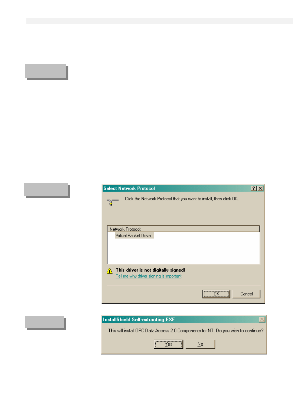
Figure 4-7
Locate File
Window
Software Installation
Select “Yes”. This will open the “Readme Information” window (Figure 4-10).
Select “Next”. This will open the “Setup Complete” window (Figure 4-11).
Select “Finish”
Figure 4-8
Select Network
Protocol
Window
Figure 4-9
InstallShield Selfextracting
EXE Window
4-6
Page 57

Figure 4-10
Readme
Information
Window
Software Installation
Figure 4-11
Setup Complete
Window
Ethernet Addresses
Edit or create a file "C:\MICON\devlist.txt" using Notepad or some other text editor. In this file, add
one line for each T6200 Controller's Ethernet addresses as follows:
4-7
Page 58

Software Installation
Primary Control Board E thernet Address
Backup Control Board Ethernet Address
UC254,00:08:9A:D2:05:02,00:0D:9A:D2:05:02,
UC255,00:08:9A:D2:06:02,00:0D:9A:D2:06:02,
BAK ID from I/O Backplane
PRI ID from I/O Backplane
Figure 4-12
devlist.txt – Notepad
Window
Figure 4-13
T6200 Controller Name
The strings are separated by a comma. The first string is the name for the T6200 Controller. The
second string is the Ethernet address for the primary control board and the third string is the Ethernet
address for the backup. Make sure there is a comma at the end of each line. There can be only one
Controller per line. Refer to Figure 4-12. The Controller/s listed in this file will be the only one/s that
the MICON OPC Server will communicate with at runtime.
The T6200 Controller name must be a unique name and should have from one to 16 alphanumeric, dash (), and/or underscore (_) characters. The name cannot contain spaces (blanks) or other symbols. The first
character of a name cannot be a dash or number. Both upper and lower case letters are accepted.
The PRI ID and BAK ID numbers on the T6200 Controller I/O Backplane is used to build the Ethernet
addresses. Refer to Figure 4-13. Add “00:” in front of each number, add “:” between every other digit,
and add “:02,” to the end.
T6200 PRI ID and
BAK ID
4-8
Page 59

T6200 Controller Operation
Push to Activate Switch 5
System Start-up 6
Replacing Control Boards 6
Loading Controller Configuration 8
Watchdog Timer 8
T6200 Controller Operation
5
Section Five
5-1
Page 60

T6200 Controller Operation
5-2
Page 61

T6200 Controller Operation
T6200 Controller Operation
The redundant T6200 Controller consists of two identical control boards, primary and backup, and one
termination panel. Refer to Figure 5-1. The primary control board is always on the left and the backup
is always on the right. Normally, the primary board is the active board and the backup board is the
standby board. These roles may be reversed. When the backup board is active, it transmits a “Backup
Active” alarm to the host.
The active board controls both the analog and discrete outputs to the field. The analog and discrete
outputs are disabled on the standby board. Refer to Figure 5-2. When the outputs are required to
feedback as inputs, the outputs of the active board are used in both boards. A primary board without a
backup is always active. The active and standby boards have the same inputs and configuration.
Push to Activate Switch
A PUSH TO ACTIVATE switch (SW1) is located at the front of each control board at the bottom.
Refer to Figure 5-3. The switch has three functions:
Used to activate a standby Controller. The NORMAL LED must be illuminated before
this Controller can be activated. If the Controller is activated, the redundant Controller will be
deactivated automatically.
This switch can also be used to clear all the configuration in the Controller memory.
This can be accomplished only during the first three seconds when the Controller is being
powered up by depressing the switch for one second or more.
Each time this switch is depressed, the Controller identification number will be
transmitted to the host over the Ethernet communications. This may be used when adding a
Controller to the network.
5-3
Page 62

FIGURE 5-1
T6200 Primary
and Backup
Control Boards
T6200 Controller Operation
Figure 5-2
T6200-C Active
and Standby
Current Outputs
System Start-up
When power is first applied, the T6200 Controller forces the analog outputs to zero and the di screte
outputs to open. Next, the T6200 Controller starts the self-test and flashes the COMM LEDs. After the
self-test has been successfully completed, the primary board will become active. The OUT LED will
illuminate on the backup board during this wait period. There must be a board in the primary positi on
when running the Controller Definition program in A/S VIEW. If the T6200 Cont roll er does not have a
primary board when power is first applied the backup board outputs will remain in their power-up reset
condition.
5-4
Page 63

h
TABLE 5-1
Control
Board LEDs
LED
ACT
(TOP)
NOR
EN1
EN2
COMM1
COMM2
OUT
T6200 Controller Operation
NAME
COLOR
DESCRIPTION
Active Green This LED shows the Active/Standby status
of the Controller. When illuminated, the
Controller is “Active” and controls the
outputs. When a backup Controller is
used, either primary or backup can be
active, but not both of them.
Normal Green The LED shows the status of the watchdog
timer. The LED is illuminated when the
microprocessor is properly toggling the
watchdog timer.
Ethernet 1 Yellow This LED will flash when data is being
transmitted or received on Ethernet 1
Ethernet 2 Yellow This LED will flash when data is being
transmitted or received on Ethernet 2
Communication 1 Green This LED will flash when data is being
transmitted or received on COMM 1 or
backup communication
Communication 2 Green This LED will flash when data is being
transmitted or received on COMM 2
Outputs Red This LED illuminates when the outputs are
inhibited. This condition normally occurs
during power up. The backup control
board cannot be active if this LED is
illuminated.
Figure 5-3
Push to
Activate Switch
Backup
Control Board
Primary
Control Board
“Push to Activate”
Switc
If the primary board has a configuration in its memory, it will start the loop processing. If the primary
boards do not have configuration, the outputs will remain in their power-up r eset condition.
At startup, the backup board's memory is always cleared, and the primary board transfers the configuration
to the backup board through the backup serial link.
During runtime operation, if a new configuration is downloaded, it automatically goes to the active board.
If the active board is the primary board, the backup board's memory is cleared, and the primary board
5-5
Page 64

transfers the configuration to the backup board through the backup serial link. The standby primary
board’s memory cannot be cleared during runtime operation without removing the board. To transfer a
configuration from a backup board to a primary board, the primary board must be removed (unplugged)
and reinstalled, clearing the memory at the same time (see Replacing Control Boards below). The
primary board, with cleared memory, will then request a configuration transfer from the active backup
board.
Replacing Control Boards
In a system with redundant boards, the backup board can be activated to allow removal of t he primary
board without upsetting the system. Depressing the PUSH TO ACTIVATE switch will activate the
backup board. The NORmal LED must be illuminated and the OUT LED must not be illuminated before
the board can be activated. When the backup board is active, it transmits a "Backup Active" alarm to the
host on the Ethernet. This alarm cannot be cleared as long as the backup board is active.
After the backup board has been activated, the primary board may be removed by pulling on the handle on
the front of the board to unplug it.
The memory must be cleared in the replacement board. To clear the memory, plug in the replacement
board and depress the PUSH TO ACTIVATE switch for one or more seconds within the first three
seconds. The OUT LED will illuminate for a few seconds while it gets the configuration from the backup
board and then compiles it. After the OUT LED goes off, depress the PUSH TO ACTIVATE switch to
activate the primary board.
If you do not clear the memory, the replacement board will retain its old configuration.
CAUTION
it is the same model and the jumper placements are the same.
Each Controller model has a different mechanical key to prevent the incorrect model from being plugged
into the termination panel.
Plug in the replacement Controller. The NORmal LED will not illuminate for a few seconds while it gets
the configuration from the Backup Controller and then compiles it. After the NORmal LED illuminates,
depress the PUSH TO ACTIVATE switch to activate the Primary Controller.
When replacing a Controller that does not have a backup and the application process is shutdown, the
Controller can just be unplugged and the matching replacement board plugged in its place. If the
replacement board has an undesirable configuration, it can be cleared by depressing the PUSH TO
ACTIVATE switch for more than one second within the first three seconds after the Controller has been
plugged in. A new configuration can be down loaded from the host.
Before plugging in a replacement Controller, verify
Refer to the jumper placement in Section Three,
T6200 Controller Operation
Hardware Installation/Maintenance.
Loading Controller Configuration
If a Controller is unplugged or power is removed long enough for the capacitor (that is used to keep the
RAM alive) to discharge (usually about one week) the above process will have to be repeated.
5-6
Page 65

Watchdog Timer
The microprocessor toggles the watchdog timer at least once every 100 milliseconds. If the watchdog
timer is not toggled within this time period, the watchdog timer will reset the microprocessor. If t he board
is on standby, the outputs will be disabled. If the board is active, control will be transferred to the backup
board. If there is no backup board or if the OUT LED is illuminated, the outputs will remain at the
condition before the watchdog timer reset the microprocessor.
If the microprocessor does not start after being reset, the watchdog timer will continue to reset the
microprocessor every 1.6 seconds. If the microprocessor does restart in a redundant system, the board will
remain in the standby mode. If there is no backup board, the primary board will resume t he active m ode.
T6200 Controller Operation
5-7
Page 66

T6200 Controller Operation
5-8
Page 67

p
Preface 2
Overview of HMI-6200 Features 3
Event Information Processing 5
Display Layout 11
General Display Description 14
Graphic Displays Configuration 17
HMI Example – Single Stage Compressor 18
Adaptation of Pre-Defined Displays 21
Surge Curve Screens 25
Custom Graphic Screens - 26
Configuring the Security System 27
Communications 30
Downloading the Updated Application 34
Section Six
O
HMI-6200 Operator Interface
6
HMI-6200
erator Interface
6-1
Page 68

HMI-6200 Operator Interface
HMI-6200
OPERATOR INTERFACE
Preface
To be effective in a small (5.7” P/PC size) footprint, the operator interface must be ergonomically
pleasing and comfortable to the user. While this may seem to be a fairly easy goal to achieve with
today's well accepted Menu Bar interfaces, a number of elements come into play with a process
controller-based environment that must be brought into proper relationship with the operator-elements
such as instant alarm access, prevention of accidental value entry, value setting accuracy, etc.
The HMI-6200 display architecture is flexible, yet clean and simple in appearance and interacts with
every application in the same manner. The windows, menus, etc. are consistent looking and behaving.
The prompting and pre-formatted type display hides the complex window access procedure and
simplifies operation to a point where a virtually untrained person can easily navigate between displays.
It provides an intuitive means of interacting with the process.
The touch screen provides for simple operator interaction. Direct touch or a pen (stylus) are used for
contact with the screen.
For lager size touch panel computers (12.1, 15 ..etc inch screen size) several displays can be grouped
on each screen. The screen grouping is accomplished by right-clicking the Group Screen on the Screen
menu of the WEB Studio software.
6-2
Page 69

Overview of HMI-6200 Features
A standard option of the T6200 Unit Automation System is to incorporate an integral 5.7 inch P/PC
based full-featured human-machine interf ace – HMI-6200.
This Operator and Engineering Interface Software offers…
- Standard and Customized Screens
- On-Line Operation and Control
- On-Line and Remote Diagnostics
- Alarm and Event Management
- Critical Event Archiving
- Trend and Historian
- OPC Compliant Client-Server Architecture
- Unit Asset Condition Management - UAM
HMI-6200 Microcontroller –
- Intel StrongARM SA1110 microprocessor
- 32 MB Flash Memory
- 64 MB SDRAM Memory
- Integrated LCD controller
- Ethernet connectivity
- CompactFlash slot
- Card Speaker
Database Management –
Object oriented database
- Fill-in-the-blank definitions
- Data accessible system wide
Standard Environment –
Based on Microsoft’s DNA architecture
- Industry standard operating system – Windows CE
- Distributed COM
- XML technology
True Multi-User Capabilities –
- Supports multiple P/PC’s and workstations
- Networkable on popular local and wide area nets
- Web enabled to serve HTML pages over the Web with
real-time data
- Allows sub-division of process responsibilities to different users
Business Interoperation –
Unit control can be integrated into a total plant/business system.
- Integrates TMC Unit Control and Business Asset technology
- Imports and exports real-time data and reports in XML
- Protected data ownership and security
HMI-6200 Operator Interface
6-3
Page 70

HMI-6200 Operator Interface
OPC Client/Server –
The build-in CE OPC Server is compatible with the StrongARM processor
Enables communication with control modules
- Open systems OPC link
- Server identifier
- Configurable data update rate
If an operator interface other than the HMI 6200 is selected
make sure that the OPC server is compatible with its processor.
Comprehensive GUI –
Based on WEB Studio, the graphical user interface offers object oriented easy to use graphics.
User-defined and pre-defined graphic displays. Used to monitor and control a TMC process.
- Pre-defined displays include:
Home; Graphics, Face-Plates; AIN/AO; DIN/DO; Alarm Summary, Alert Summary; Trend;
Historical Trend;
- Scripting language including math expressions, statistic and logical functions, module activation
functions, etc.
- Build hierarchies and networks of displays
- Displays real-time & historical data
- Translation Tool for multi-language operation
Time-Scheduled Tasks –
Provides time-based user defined operations
- Event types: Reports, Recipes, Calculations, data logs, match/logic functions or any program
- Scheduling intervals from seconds to years
- Quickly defined and interactive
- Schedules application programs
Alarms and Alerts Processing –
Provides comprehensive alarm reporting
- SOE (sequence of events) capabilities
- Individual or multiple alarm acknowledgements
- Remote Ack (acknowledge)
- User definable priorities
- User definable status colors (start, ack, norm)
- Archive storage an d call back
Real-Time and Historical Trending –
All data base points may be selected for trending
- Selectable plot scales, time spans, colors, grid sizes
- Up to 8 plots per window
- Selectable curve type (X/t, X-Y)
- Save On Trigger or Save on Tag Change selection
- Archive storage an d call back
Recipes and Reports –
Facilitates assessment of unit performance
- Easy creation of reports (without programming tool)
- Load recipes and retrieve values in XML format
6-4
Page 71

Event Information Processing
The following describes the information structure for alarm and alert handling and for t ren d a nd
historical recording
Alarm and Alert Definition –
The T6200 includes comprehensive detection and notification of alarms and alerts. Alarms are defined
as conditions which require user acknowledgement; alerts are records of actions/conditions for which
operator acknowledgement may or may not be specified (Ack is configuration selectable).
Alarm and Alert Detection –
For reliability and speed-of-response alarm and alert detection and processing takes place in the con trol
module of the T6200. All alarms and alerts are time-stamped upon detection.
Deterministic Alarming –
Deterministic alarms/alerts are generated by comparing the performance of combinations of discretes
and/or variables against pre-defined limits of alarmable conditions of operations. Practically unlimited
logic/math/selection functions are provided in the control module of the T6200 to allow for simple or
sophisticated alarm/alert interlocking.
Deterministic alarm configurations serve basically two purposes - 1) they can be used to advise or take
action based on the nature of alarm combinations or 2) deterministic alarming can also be used to
disregard alarms/events that are merely further effects of a fault that has already been recognized. Two
examples of combinational alarms would be:
- Do not generate a low flow alarm if a corresponding pump is turned off.
- Alarm on deviation of a process signal from a trip-point only if the rate of change or another variable
exceeds specification at the same time that certain valves are fully open and a feed pump is off.
HMI-6200 Operator Interface
Alarm and Alert Suppression –
Alarm and alert processing can be suppressed at the control module level. The configured suppression
may be for specific alarm/alert points or groups and is normally process condition related. Notification
of suppression is provided via alarm “cutout” attributes.
Alarm and Alert Notification –
The HMI-6200 (operation interface) provides several features for notification of alerts and alarms.
These include: HMI display, audible annunciation and optional control triggering.
6-5
Page 72

FIGURE 6-2
Alerts - Summary
Display
HMI-6200 Operator Interface
FIGURE 6-3
Alarms - History
Display
Historical Alarm and Alert Display -
The Alarm/Alert History display provides for means of viewing past Alarm and Alert events. Historical
data can be retrieved with convenient date/time selection buttons.
6-6
Page 73

FIGURE 6-4
Trend History
Definition
Windows
HMI-6200 Operator Interface
Dynamic Trending Module –
The HMI-6200 trend capability provides for viewing of real-time and historical data. A trend display
format, with up to six plots, is included.
Trend Configuration –
The contents of the Trend and the Trend History display are defined by trend window templates as
shown below.
FIGURE 6-5
Trend Points
Configuration
Window
Compressor App
6-7
Page 74

HMI-6200 Operator Interface
6-8
Page 75

FIGURE 6-6
On-Line Trend
Display
HMI-6200 Operator Interface
Trend Display –
The trend display is presented in the popular strip chart recorder format.
Historical Tend Display -
The Trend History display provides for a comprehensive means of viewing process and calculated data
over periods of time. Historical data can be retrieved with convenient date/time selection buttons
6-9
Page 76

FIGURE 6-7
Trend History
Date/Time Selection
HMI-6200 Operator Interface
6-10
Page 77

Display Layout
Preformatted displays provide the basic operations interface for: compressor /turbine contro l, continuous
process control, batch/sequence control, SCADA alarms, trends, etc. Information is presented in an
easily understood manner.
The operational displays are organized into a structural hierarchy consisting of overview(s), graphics,
face-plates, etc. Displays are called up through a simple menu bar procedure. In addition to the menus,
the user is provided with “go-to” display buttons to allow for customized window selection.
Besides the configuration at the time the systems is set up, some configuration is normally done later
on, such as building additional graphics.
Analysis of process conditions is fully supported. A standard trend display (real-time and historian
trend), alarm and alert indication (real-time and historical) and diagnostic displays allow for quick
process analysis and situation correction.
Reports and Recipe screens and the ability to retrieve values in XML format facilitate the assessment
and correlation of unit performance.
FIGURE 6-8
Operational
Display
Hierarchy -
Overview
Graphics
HMI-6200 Operator Interface
T6200
Unit Controller
MICO
HOME
U-200
T6200
Unit Controller
GRAPHIC
MICO
#1
U-200
T6200
Unit Controller
ALARM
MICO
ALERT
U-200
SUMM
T6200
Unit Controller
GRAPHIC
MICO
U-200
#2
T6200
Unit Controller
TREN
MICO
U-200
HIST
T6200
Unit Controller
MICO
GRAPHIC
U-200
#N
T6200
Unit Controller
OPER
MICO
U-200
STATUS
T6200
Unit Controller
DIAGN
MICO
FLOW
U-200
CHARTS
T6200
Unit Controller
PROC
MICO
U-200
STATUS
T6200
Unit Controller
DIAGN
MICO
FLOW
U-200
CHARTS
T6200
Unit Controller
I-LOCK
MICO
U-200
ESD
T6200
Unit Controller
DIAGN
MICO
FLOW
U-200
CHARTS
Face-Plates
T6200
Unit Controller
FACE-PL
MICO
U-200
#1
Operation
T6200
Unit Controller
FACE-PL
MICO
U-200
#2
T6200
Unit Controller
FACE-PL
MICO
U-200
#N
T6200
Unit Controller
LOOP
MICO
U-200
TUNING
/Process Displays Status/
T6200
Unit Controller
REPORT
MICO
U-200
RECIPE
Diagnostic
T6200
Unit Controller
AUX
MICO
GRAPHIC
U-200
#1 -- #N
/Aux displays
The HMI-6200 is designed to facilitate operation at all levels. It allows simplified access to the
controls, provides a logical display format, and incorporates methods for easy interaction with the
process. Operation and management may call up displays from many different unit areas for a concise
picture of unit and plant/pipeline performance.
The HMI-6200 also supports engineering functions in the creation and scheduling of reports and
recipes.
Status displays, diagnostic flow charts, tuning indication and other user-defined auxiliary displays
enable rapid situation correction.
6-11
Page 78

FIGURE 6-1
Graphic display of
a Column with
Top and Bottom
Reflux
Pre-defined
Header and Footer
template described
below
HMI-6200 Operator Interface
HMI-6200 Header and Footer Template
The Web Studio screen editor allows you to create a variety of windows and dialogs which feature user
inputs by screen selection and touch pad. The following relates to the HMI-6200’s process display
access formats that are pre-defined by a standard Header and Footer template.
Header
- Next (f) and Last (e)
- Home display access
- Graphic display(s) access
- Face-Plate display access
- Trend/Historian display access
- *** Miscellaneous display access
Footer
6-12
Page 79

HMI-6200 Operator Interface
- UAM displays access
- Alarm Summary/History display access
- Alert Summary/History display access
6-13
Page 80

General Display Description
“Home” Display –
The “Home” display typically provides for an overview presentation of the compressor performance
with an “at a glance” identification of off-normal and alarm conditions. The operator can select directly
subdisplays (Graphics, Face-Plates, Diagnostics and Operation etc.) from this display to bring details
into view.
HMI-6200 Operator Interface
Graphic Display(s) –
While pre-defined custom graphic displays meet the need of most users, many still may wish to create
additional displays that are specific to their respective TMC operations.
The displays normally consist of graphical symbols, bar-graphs and alphanumeric information. They
represent real-time database information graphically and allow for user-specific actions and control. From
the graphic display(s) the operator can also directly select sub-displays (Face-Plates, Operation and
Process Status, Diagnostics, etc.).
Face-Plate Displays –
These displays show PID “face-plates” and process control parameters associated with the displayed
loops – Anti-Surge, Incipient Surge, Capacity, Load Share, I/O Overview.
Direct go-to buttons to displays of Operation Status, Diagnostics, Interlocks, Tuning are provided.
Alarm Summary Display –
The alarm summary display identifies and summarizes all new alarm points along with other
acknowledged alarm points. It lists time of occurrence and description. The display shows 16 alarms
per page. A scroll-bar is used to access all alarms.
Alarm priority and filter as well as the message color are defined during configuration (creation of the
alarm worksheet).
The Alarm History display allows for dissemination/ diagnostics of historical alarm conditions. This
display includes convenient date and time selection.
6-14
Alert Summary Display –
In order to provide segregation between alarms and alerts/events a separate alerts group is included.
Operation and function of this display is identical to the alarm summary display.
Page 81

HMI-6200 Operator Interface
Trend Display –
The trend module displays analog and discrete points on trend of any tagged system variable. The trend
display can contain up to six variables (plots) – continuously updated. Plot colors, scale (Min, Max),
Cursor Value and time span are selectable. Curve type can either be X/t or XY.
One can store the trend points in a history file for data collection and display. The historian module
includes a dead band (for data storage reduction) and incorporates save on Trigger or Tag Change
selection. The Trend History display also contains time and date selection.
Miscellaneous Displays Operation and Process Status Displays –
Operation indication is structured to quickly and accurately determine process status and to allow for
fast response.
Diagnostic Displays –
The unit maintenance functions can be supported by diagnostic displays which provide the us er with a
flow-chart type view of the control loops.
Analog and Discrete I/O Displays –
The I/O displays provide a summary of the analog and discrete point values. Each rectangle includes
the abbreviated point name and the value.
Equipment Condition Displays –
Condition display(s) can be provided to illustrate status (Interlock, ESD status, etc.) and pertinent values
of the process equipment.
Detail Display(s)
Displays for calculation and fall-back value settings are typically included to provide an overview of
key parameters.
Reports and Recipes –
Reports can be created without needing any special programming tool (like VB, etc.). Using the report
workstheet and the scheduler, reports can be custom designed and scheduled for display and
transmission.
The recipes module (worksheet) is used to create, load and delete recipes. Recipes, in this case, means a
group of tags that have their values saved and retrieved like a database. The values can be retrieved
from the ASCII file in standard format or the XML format.
6-15
Page 82

FIGURE 6-9
Workspace Window
HMI-6200 Operator Interface
FIGURE 6-10
Scheduler –
Critical and control related timed-tasks normally reside in the T6200 control module(s). However,
timed tasks for reports, supervisory recipes, trend and math are typically handled by the HMI-6200
Scheduler module.
The timed-task module (scheduler) supports reports, logs, recipes and general actions (math and logic
functions). It provides for the scheduling, definition and detection of timed tasks. The tasks may be
scheduled to execute automatically once, or any number of times at fixed intervals as pre-defined by the
user.
The Clock event is used to trigger actions based on regular time intervals such as timers and counters.
The base time (minimum of 100 ms) is set in the Time column. In the Tag column, one must configure
the tag that will receive the result from the expression configured in the Expression column. The
Disable field can be used to prevent an expression in the line from being executed.
The Calendar event is used to trigger actions on a scheduled time. Also, it is possib le to specify a fixed
date for an event in the Date column.
The Change event is used to trigger an action upon a change in tag value (such as special trend on incipon). In the Trigger column, one must configure a tag that will be used to trigg er the event when the
change in value has occurred.
Scheduler
Configuration
Example for IncipInitiated Trending
6-16
Page 83

Graphic Displays Configuration
The HMI-6200 graphics software is a runtime-only version of the workstation PC graphics. All
configurations of graphic displays are made using a workstation PC and then downloaded to the HMI6200 P/PC Operator Interface. Once in run-time mode, the user is able to execute all runtime functional
dynamics that have been added/defined during configuration.
Powerful HMI Visualization -
A complete set of drawing and animation tools is furnished. One can create graphic objects and build
displays using any combination of drawing tools (boxes, lines, circles, text, etc.); save the graphic
objects in a library, add expressions and animation.
Dynamic Object Animation –
Considering the small (P/PC size operator interface) footprint, it is important to provide highperformance animation effects based on dynamic real-time links. The dynamic action tool offers
rotation, animation, analog color, flash, etc.
Summary of Graphic Features:
- High Performance Object-based Graphics
- Powerful Display Creation Tools
- Dynamic Animation
- Import Popular Display Formats
- Extensive Symbol Library
- Built-in Math, Expressions and Calculations
HMI-6200 Operator Interface
FIGURE 6-11
Graphics
Configuration
Screen
6-17
Page 84

HMI Example – Single Stage Compressor
The following shows an example of a T6200 Compressor Unit HMI for single stage centrifugal
machines.
The HMI is designed to facilitate operation at all levels. It permits simplified access to the unit,
provides a logical display hierarchy, and a choice of navigation for easy interaction with the process.
FIGURE 6-12
Compressor Home
Screens display the
Performance Map
and process values
at “a glance”
HMI-6200 Operator Interface
FIGURE 6-13
Compressor Graphic
Screens provide for
visual overview and
for control
Graphic Overview Display/Control
6-18
Page 85

FIGURE 6-14
Compressor FacePlate
Screens and Aux
Displays provide for
traditional operation
convenience
HMI-6200 Operator Interface
A/S Face-Plate Display/Control
LS Face-Plate Display/Control
Capacity Face-Plate Display/Control
LSE Face-Plate Display/Control
Lube Oil Display/Control
Seal Gas Display/Control
6-19
Page 86

FIGURE 6-15
Compressor Driver
Display provides for
Turbine Status
Indication
HMI-6200 Operator Interface
From operator displays to maintenance screens to engineering displays th e HMI-6200 covers the full
interface spectrum. This color LCD display represents an HMI with full DCS/SCADA capabilities. It
provides a complete “window” on the process by which one can operate/control, maintain and manage
the process unit.
Driver Status Display
FIGURE 6-16
Quench Control
Overload Contro l
Suction Control –
all on one display
Quench & Overload Face Plates
6-20
Page 87

HMI-6200 Operator Interface
FIGURE 6-17
Maintenance Screens
facilitate process and
control diagnostics
Operation Status Display
Process Status Display
Load Share Diagnostic Display
Loop Tuning Display/Entry
Adaptation of Pre-Defined Displays
The general HMI-6200 operator interface consists of preformatted displays. These displays are
structured into overview(s), graphics, face-plates, trend, etc. The user is provided with an operator
Load Efficiency Diagnostic Display
Interlock Display
6-21
Page 88

HMI-6200 Operator Interface
interface that allows for easy customization and adaptation to the specific process/plant configuration.
Besides adaptation at the time of system set-up, some display configuration is usually done later on.
System Requirements
The HMI-6200 operator interface is based on Web Studio. To develop/adapt an application with Web
Studio software, the following hardware and software is recommended for the Host computer...
- IBM-compatible computer with an Intel compatible processor
- Windows NT/XP/2000 operating system
- 128 MB of RAM
- 200 MB of free hard disk space
- MS Internet Explorer 4.0 or higher
- CD-ROM drive (only for initial setup)
- Ethernet connection for downloading applications
Installing Web Studio
The installation CD is used to install InduSoft Web Studio. The development environment runs on
Microsoft Windows NT/XP/2000; the CEView runtime environment, which is downloaded to the HMI6200 operator interface, comes pre-installed on the runtime workstation.
The Web Studio provides the tools needed to adapt the pre-formatted HMI-6200 operator interface to
the customer’s specific application. Refer to InduSoft Web Studio installation instructions.
Screen Editing and Configuration
The screen editor p ermits to change th e pre-defined ICS TRIPLEX screen s and create new s creens and
dialogs. The configuration task allows for changing any element in the configuration, including the
database. An emulation of the revised/extended application can be run and tested on the development
computer before downloading it to the HMI-6200 operator interface.
Refer to the on-line Technical Reference and User Manual under the Help tab for detailed instructions.
Tag Database
The T6200 is delivered with a pre-configured Application Tag database. These tags are shown/declared
under the Tag List and Datasheet View of the Database tab.
The pre-configured Application Tag database consists of generic tags
generic tag structure be retained and that custom tag requirements be accommodated by simple labels
on faceplates, etc. (not database tag changes).
. It is recommended that this
6-22
Page 89

FIGURE 6-18
Workspace Window
Database Tab
selection of
Application Tags
HMI-6200 Operator Interface
Class Tags
Loop tags – PV, SP, Out, Mode – are defined in a tag format called “classes”. This permits a high
degree of encapsulation. When a class-type tag is created, it does not contain a single value, but a set of
values associated with the loop. When a new loop is created, it is recommended to follow the predefined class type definition.
Database Exercise
In the development computer Workspace window, select the Database tab. Click the Application Tags
folder to expand it and double-click the Datasheet View line to open the database worksheet.
FIGURE 6-19
Application
Datasheet
Analog Input
configuration
Note that the database was updated during the development (tags appear as they are created and empty
spaces are present as a result of deletions).
For this database exercise example, we add/define a discharge temperature tag and associated alarm
tags. We need to configure the Application Datasheet as follows (in order to fill in the field, click on
the field after the last defined tag and type the data).
On line # 64… Name: type
Td_a; Array Size: type 3 (four stage compressor, 0-3); Type: click ▼ and select Real; Description: type
Td Absolute (Deg R or K); Web Data: click ▼ and select Local or Server.
On line # 65… Name: type
Td_FB; Array Size: type 3; Type: click ▼ and select Boolean; Description: type FALLBACK Disch
Temp; Web Data: click ▼ and select Local or Server.
Repeat the data entry on line # 66 as shown below, to define the high temp alarm.
We have created an additional analog input with High and FB alarms; now expand the Tag List folder to
verify the database addition you have created. Note that during the screen development, when you type
in a nonexistent tag, Web Studio will prompt you to check if you desire to create a new tag (if you
accept, it will create a window which permits to create the tag).
6-23
Page 90

HMI-6200 Operator Interface
Changing/Expanding Screens
Before changing and/or expanding screens, you should consider the pre-defined structure of the
application screens. For new screens, you can use existing screens (including the Standard screen),
saving it under different names. To update/change an existing screen, insert/change the objects in the
window between the he ader and footer. It is not recommended to change the header or footer
arrangement itself.
The standard header and footer was used as template for all application screens. The footer area
includes a single line alarm object that displays the latest active alarm. The individual objects that make
up graphics, faceplates, etc. on the application screens are taken from the pre-configured objects in the
Library.
Database Updates/Additions Recommendation:
For most applications there are no update or addition requirements of the pre-defined Tags that are
stored in the Application Database. Or in other words, the pre-defined generic Application Database
does not have to be changed in most cases; user tags are accommodated by tag labels (not database tags)
‘drawn’ with the screen editors’ A/N characters.
If updating/changing Application Tags is required, keep the following syntax rules in mind:
• Although the maximum Tag length is 32 characters, Tags should be as short as possible
(typically not exceeding 12 characters)
• Tags must begin with a letter. They can be composed of letters, numbers, and the underscore
character (_)
• The tag name must be different from the Web Studios’ reserved internal tag names and math
functions
• While tag names are NOT case sensitive, both uppercase and lowercase characters should be
used to make tag names more clear
Make sure that No
corner DRAG status). Enable DRAG (strike Ctrl > D on keyboard) only if you need to move/reposition
objects on the screen.
DRAG is set before working with any screen (see screen, lower right-hand
6-24
Page 91

Surge Curve Screens
FIGURE 6-20
Surge CurveOp Point Display:
X/Y Map
SLL Configuration
below
HMI-6200 Operator Interface
- Surge Curve Configuration: The Surge Limit Line (SLL) is arranged in a lookup table format
with linear vector interpolation. Up to 20 points can be defined. The X points define the domain
input – Hp,sim. The Y points define the range (output) – Q2,sim.
- Click on Edit Mode Enable check. Drag the surge points to the desired position or use the
Up/Down buttons to position the surge points.
6-25
Page 92

Custom Graphic Screens
While the pre-defined operating displays that are provided with the HMI-6200 operator interface meet
the needs of some users, many still wish to create displays that are specific to their respective unit
operations. Like the pre-defined displays, user-defined graphic displays are constructed via the Web
Studio Object Toolbar and by importing symbols from the Library.
FIGURE 6-21
Overview Graphic
Stage Graphics
Screens:
Custom Graphics
generated from predefined examples
HMI-6200 Operator Interface
The Overview screen (on left hand side above) is customized to provide a key variable type graphical
representation of the actual multi-stage CO compressor application.
The Stage graphic screen (on right hand side above) is configured to show the individual compressor
stages. One graphic screen is provided for each stage.
Control of process equipment should be built into the graphic displays so that an operator can select
Loops, etc. and command the equipment associated with it. By providing users with graphical
illustrations of the equipment, control is simplified and easier to understand. It is however
recommended that several steps requiring confirmation and authorization of control be used to minimize
the chance of accidentally actuating equipment. Carefully consider the Object Properties (such as
Confirm and Password) and evaluate if Security (see Configuration of the Security System) should be
enabled for the screen and/or specific control variables/points.
6-26
Page 93

Configuring the Security System
The Security folder allows you to define Groups and Users as well as their access privileges to Web
Studio tools and to the application. Through the Database tab, you can tailor Groups and Users to your
security needs.
FIGURE 6-22
Workspace Window
Task Tab
Selection of
Security
HMI-6200 Operator Interface
FIGURE 6-23
Security
Group Account
Window
Development Group
- Password: __________ is pre-defined as the Main Password. You will need to enter the password
each time you access the Security System (so it is mandatory that your remember it). To change the
Main Password contact the factory.
- Development Group: Double-click Development, enter the Password, and the Group Account
window will open.
In this window, you enable/disable the Development Group operations and you set the range levels.
Verify that the Security Levels and Access are defined in accordance with your application
requirements.
6-27
Page 94
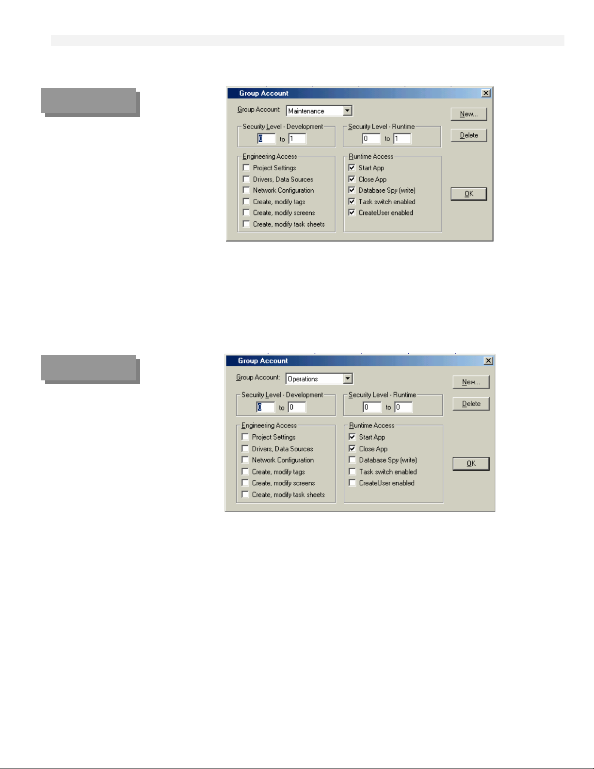
FIGURE 6-24
Security
Group Account Window
Maintenance Group
HMI-6200 Operator Interface
- Maintenance Group: Double-click Maintenance, enter the Password, and the Group Account
window will open.
FIGURE 6-25
Security
Group Account Window
Operations Group
In this window you enable/disable the Maintenance Group operations an d you set the range levels.
Verify that the Security Levels and Access are defined in accordance with your application
requirements.
- Operations Group: Double-click Operations, enter the Password, and the Group Account window
will open.
In this window you enable/disable the Operations Group operations and you set the range levels. Verify
that the Security Levels and Access are defined in accordance with your application requirements.
6-28
Page 95

FIGURE 6-26
p
User Account
Windows
- Dev1
- Maint1
- O
FIGURE 6-27
HMI-6200 Operator Interface
- Users: Double-click the User Account labels of the Security System window, enter the Password,
and the individual User Account windows will open.
1
In these windows, you create and maintain accounts for application users. Verify (and if needed redefine) the application users that will be in each group in the Group Account list. Users can also be
accessed by selecting the User option under Insert on the Main Menu Bar.
Password Button – Opens the User Password window, in which you can define a password for the user.
The pre-defined User Password is 64266.
- Guest User: After you initialize Web Studio, a default user is logged on the Guest user. If no user is
logged on or the current user has logged off, Guest user is automatically logged on. Thus, the Guest
group has default privileges. Since the installation parameters of the Guest group leave all tasks
enabled, you should change it and set as few privileges as you want for a star t up procedure.
Log On/Log Off: This utility is used to log on or off. For development purposes, you can log on or off
by selecting Logon under Project on the Main Menu Bar. The Log on/off feature on the HMI-6200
operator interface is provided by the Log on/off button (using the Web Studio Scripting Language
function) on the Miscellaneous screen (Misc scr). The pre-defined Log On password is 64266.
Log On
Window
Security System Review/Setup
Before beginning to verify/change the security system, it is important to have the groups and users
you want to configure in mind. You need to define the rights that each group has in your
environment. Each group has a range for the level in Development and Runtime. You should carefully
review the Security of all operation/maintenance/engineering screens (Screen Attributes, Security) and
the individual point security access on those screens.
Do not forget to review Object Properties for security access (Security level entry) of critical
buttons (with commands configured to turn on/off equipment) and of critical pre-set
calculation/fallback values.
6-29
Page 96

Communications
OPC Communication
The Web Studio OPC Client module communicates with the MICON OPC Server module using the
OPC Data Access Standard. The Tag Names passed between the OPC Client and Server are defined
under OPC in the Comm tab.
FIGURE 6-28
Workspace Window
Comm Tab
Selection of
OPC Sheets
OPC Worksheets: Double-click on the desire OPC item (GEN, AI/AO, Stage) to open the OPC Client
worksheets.
HMI-6200 Operator Interface
FIGURE 6-29
OPC Worksheet:
GENeral Parameters
6-30
Page 97

FIGURE 6-30
OPC Worksheets:
Stage#1 Parameters
HMI-6200 Operator Interface
Verify that all
Name and are associated with the correct OPC Server item. Also, make sure that tags are not
dynamic tags required by the HMI-6200 Operator Interface are listed under Tag
selected as Scan Always unless the specific tags require continuous scanning, such as Alarm/Alert
related tags.
Tag Names are obtained from the Database (double-click on Tag Name column). To associate the Tag
Name to the OPC Server item, right click on the item column and hit OPC Browser. This enables you
to browse all the OPC Server configured items. If the T6200 connection is not already established it
will open the OPC Server link.
6-31
Page 98

FIGURE 6-31
HMI-6200 Operator Interface
WEB Communication:
Web Studio allows you to save your application screens in HTML format and export them to Internet
Browsers (Internet Explorer).
You need to set the parameters in the Web tab in the Program Settings dialog window and save the
screens which you desire for Web communications as HTML (menu File – Save as HTML). Caution:
The Web Pages generated by the Save As HTML function are independent of the screen file they were
generated from. As such if you make a change to the Display Screen that change will not appear on the
Web page until you again Save As HTML.
Any tags which are used to display data or input commands need to have their web settings changed to
server in order to communicate over the web. Select Application Tags in the Database and verify the
Web Data column.
Application Datasheet
Database Tab
Web Data selection
FIGURE 6-32
Project Settings
Web Tab
The computer where the HTML files are stored (Page Server) must be a WEB Server (HTTP Server
driver) and the computer where the application is running (Data Server) should have a fixed IP address.
Note the Page Server and the WEB Server can, but do not have to be, the same computer. For T6200,
the Page and WEB Servers are both contained in the operator interface.
To be able to view your web pages you must first configure the web setting. These can be found in the
Project Settings window under the Web tab (see above). First you need to input the Data Server IP
Address, this is the IP address where the application is running. Next you need to enter the URL in the
following format: http://<the IP address of the unit where the web server is running>/<path from
the server to the web page directory>/. Once these two fields are correct click the ok button. Then
go to Tools on the menu bar and select Verify application (if you have any windows open in the
development system Studio will demand you close them before verifying the application).
Caution: If you change any of the web information under the Project Settings you will need to ReVerify the application for the new setting to take affect. Because the Web Pages Display information
from the application through the Web Server, the Runtime System, the Web Server and the TCP/IP
Server need to be running to view the Web Pages.
6-32
Page 99

FIGURE 6-33
UAM Report
Screen
Real-Time
Web Data
HMI-6200 Operator Interface
Once all the settings are correct, turn on the Web Server then run the application. With both of these
running you should be able to use Internet Explorer to connect to the application By selecting the URL
(http://<the IP address of the unit where the web server is running>/<path from the server to the
web page directory>/<application screen name>.html). A prompt for a username and password will
appear, enter one of the username and passwords from the security section. Once the screen appears
you can interact with the application.
Example: UAM Report screen on-line data exported to Internet Explorer.
6-33
Page 100

Downloading the Updated Application
After the adaptation of the pre-defined displays is completed, connect the development computer to the
controller operator interface via a direct HMI Crossover Ethernet cable or via the controllers’ Primary
Ethernet connection (T6200 rear termination panel, Ethernet 1). If the connection is made through the
Primary Ethernet at the controller termination panel, make sure that the T6200 control board(s) is
unplugged and that the connection from the termination panel is made direct
computer using a standard Ethernet cable.
HMI-6200 operator interface Arrangement
Select the Miscellaneous Screen (click on the *** button on the Header of the operator interface
display) Log Off and press the CEViewSD (CE View Shutdown, grayed out before Log Off
confirmation) button on lower right area of the screen. The operator interface will exit the CE View
program and display a Remote Agent window.
FIGURE 6-34
Button
Log On/Off and
CEViewSD on
Misc *** Screen
HMI-6200 Operator Interface
to the development
6-34
- Remote Agent Window
The user needs to move the "Remote Agent" window down only if he cannot see the information that he
wants to see. Typically, this will be required in order to expose the “My Computer” and “T6200
Configuration” icons.
- Delete existing COMPR_~1 Folder: Double-click the My Computer icon and then double-click the
IPSM folder icon to access the COMPR_~1 folder. Click the COMPR_~1 folder and click File and
Delete. The “Confirm Folder Delete” pop-up window with the text “Are you sure you want to remove
the folder ‘COMPR_~1’and all its contents?” will appear. Press Yes and close the pop-up. The
COMPR_~1 folder will be deleted. Close the window. The Remote Agent window (as it was previously
positioned) will appear.
 Loading...