

Page 1

ICS Regent
Important!
®
PD-6048
MODBUS Master Package
for
MODBUS Master Function Block
The MODBUS Master package for W
package which allows the user to MODBUS Master function blocks for
Regent application programs. W
seamlessly integrated with the base WINTERPRET
MODBUS Master function blocks allow the Regent to use devices which
respond to MODBUS commands to collect and disseminate data for non
safety-related application.
hen installed on the PC, the package is
INTERPRET
W
INTERPRET
(T3837)
Issue 1, August, 96
is an add-in software
software.
-
Software Installation
The MODBUS Master package is installed on the PC running the
W
INTERPRET application software. The WINTERPRET
provides the necessary installation software to install this add-in package.
The package should be install
the W
INTERPRET
Installation Procedure
The files on the MODBUS Master package diskette are in compressed
form. You cannot simply copy the files to your hard drive — they must be
decompressed before they will run. You must have the W
package distribution disk in order to run the setup procedure to install the
MODBUS Master package.
To install the MODBUS Master package, use the following sequence:
1.
Insert the WINTERPRET base package distribution disk into drive A: or
B:
2.
Start Windows (if it isn’t already running).
3.
Choose Run from the Program Manager’s File menu.
base package.
base package
ed at the same time or after you have installed
INTERPRET
base
Industrial Control Services
(Issue 1)
1
Page 2

MODBUS Master Package for
4. Type a:\
base package disk in drive B: type b:\
press ENTER.
5. In the WINTERPRET
which you have installed the W
that you have already installed W
6. In t
Master package box.
7. Choose
When the installation is completed, you can run the WINTERPRET
application and create MODBUS Master function blocks in your
application programs.
he W
setup.exe
INTERPRET
OK
in the text box. (if you inserted the WINTERPRET
Setup dialog box enter the name of the directory in
Installation dialog box check the MODBUS
to have the setup program install the package software.
W
INTERPRET
setup.exe
INTERPRET
INTERPRET
(T3837)
.) Choose OK or
base package (This assumes
). Choose
Continue.
Working with MODBUS Master Function Blocks
MODBUS Master function blocks are created as part of an application
program which may also contain other types of function blocks. A single
application program is made up of as many as 50 function blocks of any
type or combination.
When you installed the MODBUS Master package, additional software
was added to W
function blocks. With this additional software you can create MODBUS
Master function blocks by opening a project, opening a program, and
opening (or creating) a function block.
The code generated by W
(MODBUS Master function block code) responds to control signals,
prepares MODBUS commands to be sent, decodes received MODBUS
responses, and in general performs the operations that are associated with a
MODBUS Master.
The MODBUS Master code is executed in the Regent in the same manner
as any other function block code. It is called once per application scan as
long as the program to which the MODBUS Master function block belongs
is in the run state. Instead of performing a complete MODBUS scan each
INTERPRET
INTERPRET
to allow you to work with MODBUS Master
for the MODBUS Master
PD-6048 August, 96
(Issue 1)
2
Page 3

MODBUS Master Package for
time it is called, the MODBUS Master function block code splits up the
tasks so that it can be done a
a time. This allows the Regent system to remain responsive, as well as
eliminating the potential loss of time while waiting for MODBUS responses.
For an overview about Regent application programs and function blocks
and how to create them using W
with Programs and Function Blocks
little at
INTERPRET
W
INTERPRET
, refer to Section 5,
, in the Regent User’s Guide.
(T3837)
Working
Using MODBUS Master Function Blocks
The MODBUS Master function block allows the user to specify the
following Regent variables:
·
Variables to receive data from MODBUS slaves
·
Variables to be the source of data sent to MODBUS slaves
·
Variables to serve as control signals for the function block
·
Variables to receive the current status and other information about the
function block.
Each Regent variable used to send or receive data may be associated with a
different MODBUS node and address. The user may specify which port on
the Regent to use, including the s
configuration.
The MODBUS Master function block compiler may be invoked from the
File menu in the MODBUS function block editor when the editor is closed
and the changes have been saved for the current function block. The
compiler translates the user’s inputs from the source file into an object file to
be loaded into and executed in the Regent.
The compiler has two separate phases: registration and generation. In the
registration phase, the compiler registers t
from the project dictionary. The generation phase consists of parameter
validation followed by code and data segments generation. The registration
phase follows the conventions (and requirements) imposed by other
W
INTERPRET
each function block compiler, and is where MODBUS-Master-specific
code is introduced.
function block compilers. The generation phase is unique to
election of a secondary port for a dual-link
ag names and retrieves definitions
PD-6048 August, 96
(Issue 1)
3
Page 4

MODBUS Master Package for
Name
Size Type
Description
E
NABLE
Coil Input
Enables execution of the function block. Energize to
execute the function block.
E
RROR
Coil
Output
Enunciates a MODBUS function block error.
Energized when an error occurs.
R
ESET
Coil Input
Resets the error information. Energize to reset the
information. While energized, no errors w
ill be
reported.
N
ODE
Word
Output
The MODBUS node associated with the error. 0 when
there is no error.
C
ODE
Word
Output
The MODBUS function block error code. 0 when there
is no error.
T
IME
Float
Output
The time it took to complete the last MODBUS scan in
ms. 0 until a scan has been completed.
T
OGGLE
Coil
Output
This control signal changes state at the beginning of
each MODBUS scan. (Its period it typically 2 *
Time)
W
INTERPRET
(T3837)
Operation
The MODBUS function block uses control signals to report information and
accept runtime control
used like normal Regent variables. Table 1 identifies these control signals.
Table 1 - Control Signals
E
NABLE
E
NABLE is de
and all other signals are invalid (exception: the RESET
honored).
E
RROR
enunciates any errors that the MODBUS function block code
encounters.
N
ODE
and
when
E
RROR is active. NODE
a zero [0] indicating the MODBUS master itself).
specific MODBUS exception code.
The
T
OGGLE
the initial scan,
T
OGGLE
desired instead of a toggle, external application code (in the same program)
may reset
directives. The signals are user defined, and may be
controls the execution of the function block at runtime. When
-
ener
gized (OFF), the function block code is not executed
input signal will still be
C
ODE
are used to further define an error. They are valid only
contains the MODBUS node that is in error (
C
ODE contains the
state changes each time a MODBUS
T
IME
contains the length (in ms) of the MODBUS scan.
is initialized to de-energized (OFF) for the initial scan. If a pulse is
T
OGGLE
to the de-energized state after a rising edge is detected.
scan is completed. After
PD-6048 August, 96
(Issue 1)
4
Page 5

MODBUS Master Package for
Field Size
Description
Node Byte
The MODBUS node to broadcast this command to.
Function
Byte
The MODBUS function to broadcast.
Address
Word
The starting MODBUS address for this command.
Count
Word
The number of MODBUS variables to be returned.
CRC Word
The pre-calculated CRC for the MODBUS command.
Offset
Word
The index into the Read Var table for the initial MODBUS
variable.
Reserved
Word
Reserved for internal use.
Field Size
Description
Value
Word
The value of the regent varia
ble.
Note:
W
INTERPRET
(T3837)
Tables define the work that the MODBUS function block performs. The
primary table used is the ‘Read Command’ (RC) table. Each entry in the
RC table is eight bytes wide, with the first six bytes corresponding exactly
to the same fields in a MODBUS command. Each entry (starting with the
first) in the RC table sends a MODBUS command. When the response is
received, the Count field is used to decode the received data. The Index
field, in conjunction with the Read Variable table, is used to store the data in
its proper place. Tables 2 and 3 define the Read Command and Read
Variable Tables, respectively.
Table 2 - Read Command Table
Table 3 - Read Variable Table
When each entry in the Read Command table has been sent, the function
block code waits for all the replies to be returned. When all of the replies
have been received and processed, a single MODBUS scan has been
completed. At the start of the next MODBUS scan, the entire process
starts over at the beginning of the RC table.
Abstractly, the RC table can be thought of as a “Read” queue. This queue is
replenished at the start of each MODBUS scan, and is empty at the scan’s
completion. Future pseu
queue as the READQ.
PD-6048 August, 96
(Issue 1)
do code examples refer to the abstract RC table
5
Page 6

MODBUS Master Package for
Field Size
Description
Node Byte
The MODBUS node to notify when the v
alue changes.
Function
Byte
The MODBUS function to use for notification.
MODBUS
Address
Word
The MODBUS address to use for notification.
Value
Word
The current value of the variable.
CRC Word
Placeholder for the run-time calculated CRC of the MODBUS
command.
Last Value
Word
The last known value of the variable.
Reserved
Word
Reserved for internal use.
Note:
W
INTERPRET
(T3837)
The ‘Write Command’ (WC) table is also used by the MODBUS master
function block code. In many ways, the WC table is similar to the RC table.
However, the WC table does not utilize a corresponding Write Variable
table because each “Write” only references a single variable. Table 4
defines the Write Command Table.
Table 4 - Write Command Table
Every application scan the function block code is executed, each variable
defined in the WC table is examined by comparing its current value to the
co
ntents of the Last Value field. If the two value differ, the Send Flag field is
set and the current value is copied into the Last Value field.
Each entry in the WC table, with the Send Flag set, causes a MODBUS
command to be sent. When the response is received, the Send Flag for that
variable is cleared. For the initial MODBUS scan, the Send Flag field is set
for every entry in the table. The WC table is processed from the initial entry
to the final entry in sequence. If no more MODBUS commands can be
sen
t, WC processing stops and resumes again on the same entry the next
time the function block code is executed.
PD-6048 August, 96
Abstractly, the WC table can be thought of as a “Write” queue. This queue
is full for the initial MODBUS scan. Future pseudo code example refer to
the abstract WC table queue as the WRITEQ.
The tasks performed each time the function block code is executed are as
follows:
· ENABLE
·
is checked to see if the function block should be executed.
A check is made to see if this is the initial MODBUS scan. If so, local
variables and tables are initialized.
(Issue 1)
6
Page 7

MODBUS Master Package for
·
A check is made to see if this is the start of a MODBUS scan. If so, the
‘MODBUS Scan Time’ timer is reset.
·
Each “Write” variable is check to see if it has changed state (or value),
and those that have are added to the WRITEQ.
·
Outgoing packets are sent.
While !FULL(SENDQ)
If !EMPTY
(WRITWQ)
ENQ(SENDQ, DEQ(WRITWQ))
Else If !EMPTY(READQ)
ENQ(SENDQ, DEQ(READQ))
End If
End While
·
Incoming responses are received, and the appropriate actions are
taken.
·
While !EMPTY(RECVQ)
PROCESS(DEQ(RECVQ))
End While
A check is made to see if this is the end of the MODBUS scan. If so,
copy the timer and toggle the toggle.
·
RESET
is checked to see if the error signals should be cleared. This
occurs even if the function block is not executed.
W
INTERPRET
(T3837)
The MODBUS function block code keeps track of how many me
ssages
are outstanding by incrementing a counter for each ENQ(SENDQ,
DEQ(READQ)), and decrementing the same counter for each
DEQ(RECVQ) when the response is a “Read” response. A MODBUS
scan is considered complete when the counter is zero (0) and the READQ
is empty (COUNT == 0 && EMPTY(READQ)).
At the beginning of each MODBUS scan, a copy of the system millisecond
timer is made. At the completion of a MODBUS scan, this value is copied
into the T
IME
variable and the
T
OGGLE
signal is inverted.
Placing a MODB
US command on the SENDQ involves copying the
MODBUS command to a buffer, generating the appropriate error-check
code, and sending the command to the correct port (primary or secondary).
Internal variables are used to determine the port.
If a secondary port was defined, once each MODBUS scan the initial
MODBUS ‘Read Command’ for each node is sent via the secondary port.
The result of this command is ignored, it is used only to check for a valid
connection. The MODBUS Node table is used to track the status o
node’s response. Table 5 defines the MODBUS Node Table.
f each
PD-6048 August, 96
(Issue 1)
7
Page 8

MODBUS Master Package for
Field Size
Description
Node Byte
A MODBUS slave node
Reserved
Byte
Reserved for internal use.
Field Type
Description
Primary Port
Constant
Must be a number between 2 and 6.
Secondary Port
Constant
If specified, must be a number between 1 and 6 and
cannot be equal to the value specified for the
Primary Port. If not specified, a secondary MODBUS
port will not be used.
W
INTERPRET
(T3837)
Table 5 - MODBUS Node Table
If a non-MODBUS error is reported for any MODBUS slave on the
current primary port, the ports are swapped and the secondary port is used
as the primary port for the next MODBUS scan. If no errors are reported,
the Primary port is used for the next MODBUS scan. This approach results
in the MODBUS ma
diagnostic error, and remaining there until another error occurs.
ster switching over to the secondary port on any
When the responses are being processed, any MODBUS exceptions
energize the E
RROR
signal. If the
N
ODE
and
C
ODE
variables are both zero,
the MODBUS node and exception code are copied into them. This action
preserves the initial MODBUS error until
RESET is activated.
In addition to reporting MODBUS exception codes, some additional error
information is reported. In these cases, the
N
ODE
variable
is set to an invalid
MODBUS node number (0 or 248+). Just before the end of each
execution scan, the RESET signal is examined. If it is energized (ON), the
E
RROR
signal is de-energized (turned OFF) and the
variables are set to zero.
As long as the
no MODBUS errors are reported
R
ESET
N
ODE
and
C
ODE
signal remains energized,
Validation
Before any code is generated, all parameters are validated according to the
criteria presented in Table 6.
Table 6 - Parameter Validation Rules
PD-6048 August, 96
(Issue 1)
8
Page 9

MODBUS Master Package for
Field Type
Description
E
NABLE
Tag
If specified, must be the name of a valid bit variable.
If not specified, the MODBUS function block is
assumed to always be enabled.
R
ESET
Tag
If specified, must be the name of a valid bit variable.
If not specified, the
E
RROR
o
utput can only be
cleared by stopping, and then restarting the
MODBUS function block.
E
RROR
Tag
If specified, must be the name of a valid bit variable.
C
ODE
Tag
If specified, must be the name of a valid word
variable.
N
ODE
Tag
If specified, must be the name of a valid word
variable.
T
IME
Tag
If specified, must be the name of a valid floating
point variable.
T
OGGLE
Tag
If specified, must be the name of a valid bit variable.
Field Type
Description
Name Tag
Must be the name of a valid variable. The size and
usage of the variable must match the attributes as
specified by the value of the Address field. (Refer to
Table 8 for additional information.)
Address
Constant
Must be between 0 and 49,999.
Node
Constant
Must be between 1 and 247.
Usage Switch
Must specify either Read or Write.
Address Range
Regent Type
MODBUS Type
MODBUS Cmd
Usage
0
9999
Bit Variable
Coil 01
Read or Write
10000
19999
Bit Variable
Input 02
Read Only
20000
29999
Reserved - - -
30000
39999
Word Variable
Input Register
04
Read Only
40000
49999
Word Variable
Holding register
03
Read or Write
W
INTERPRET
(T3837)
A rule violation results in an error message, but the validation procedure
con
tinues until all parameters have been checked. After the parameters are
checked, each variable definition is validated according to the criteria
presented in Table 7.
Table 7 - Variable Definition Validation Rules
PD-6048 August, 96
(Issue 1)
9
Page 10

MODBUS Master Package for
W
INTERPRET
(T3837)
A rule violation results in an error message, but the validation procedure
continues until all variables have been checked. The special condition where
there are no variables defined also generates an error message. The
compiler proceeds only after all parameters and variables have been
validated and no errors have occurred.
The special condition where there are no variables defined also generates an
error message. The compiler proceeds only after all parameters and
variables have been validated and no errors have occurred.
Generation
After all parameters and variables have been validated, the compiler
generates the code and da
ta segments for the function block. The majority
of the code segment remains the same across all MODBUS Master
function blocks, because the specific behavior of the MODBUS Master is
defined in the tables generated as a part of the data segment.
PD-6048 August, 96
(Issue 1)
10
Page 11
MODBUS Master Package for
W
INTERPRET
(T3837)
Using the MODBUS Master Function Block Editor
MODBUS Master function blocks are created using Add Function Block
or Insert Function Block from the Program Editor. After you have created a
new function block, the MODBUS Master Function Block Editor window
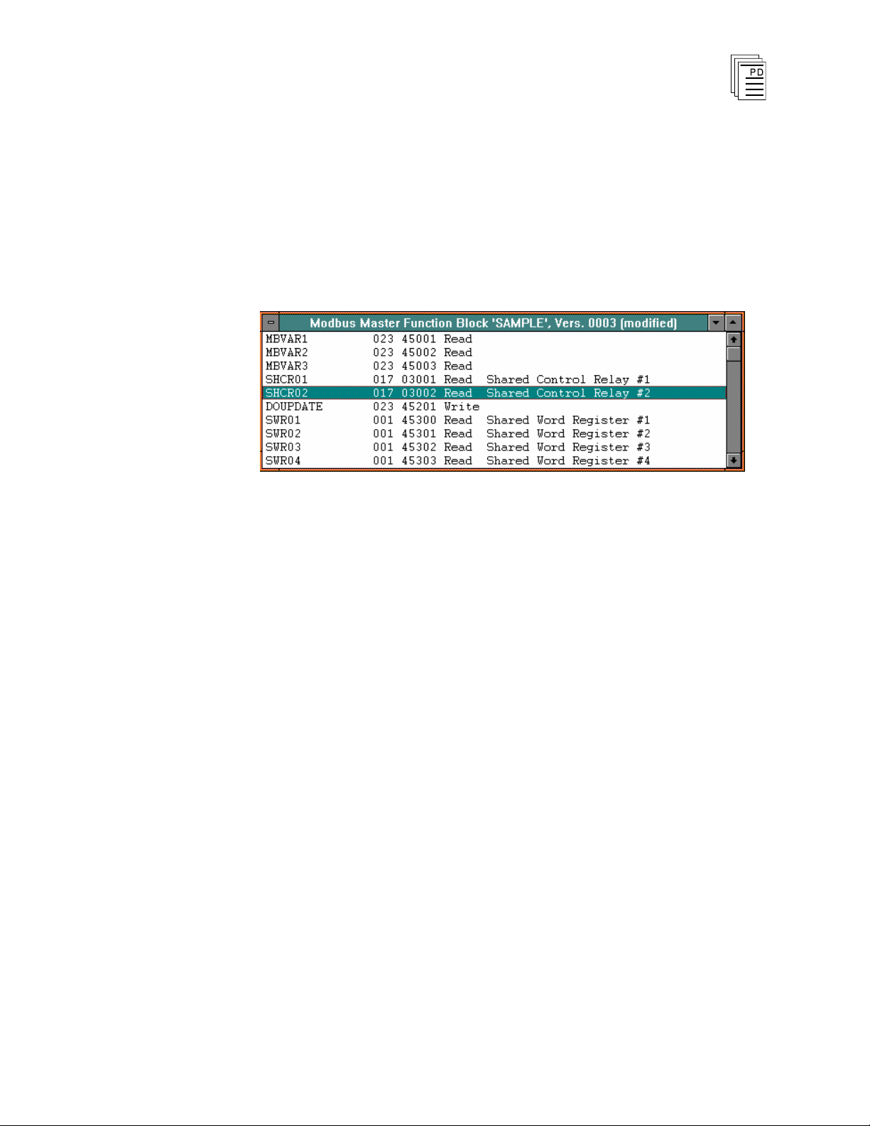
is opened
Figure 1. The MODBUS Master Function Block Editor Window
The primary user interface for the MODBUS Master function block will be
the MODBUS Master function block window. This window displays a list
of variables known to the MODBUS Master function block. Each line
includes the variable’s name, type, MODBUS node, MODBUS address,
and whether the MODBUS master is Read or Write.
as shown in Figure 1.
The MODBUS Master function block compiler may be invoked from the
File menu in the MODBUS function block edi
and the changes have been saved for the current function block. The
compiler translates the user’s inputs from the source file into an object file to
be loaded into and executed in the Regent.
Using drop-down menus, you select commands to configure and print the
function block and perform other options.
File Menu
The File Menu allows you to access the standard function block file
commands including Save Function Block, Revert to Last Saved, Compile,
View Error Messages, Edit Fu
Block Details, Print Function Block, Print Setup, Log Off, and Exit. For
more information on these commands, refer to
Function Blocks
PD-6048 August, 96
(Issue 1)
tor when the editor is closed
nction Block Description, Edit Function
Commands Common to All
in Section 5 of the Regent Ò + Plus User’s Guide.
11
Page 12

MODBUS Master Package for
W
INTERPRET
(T3837)
Edit Menu
The Edit menu (see Figure 2) allows you to select Add Variable, Edit
Variable, Insert Variable, Delete Variable, Add Multiple, and Edit
Parameters commands.
Figure 2. The
Edit Menu
Add Variable/Edit Variable/Insert Variable
The Add Variable command allows you to add a variable to the end of the
function block variable list. The Edit Variable command allows you to edit a
selected variable. The Insert Variable command allow to enter a new
variable.
After choosing to add, edit, or insert a variable, the dialog box shown in
Figure 3 opens.
PD-6048 August, 96
(Issue 1)
Figure 3. The MODBUS Variable Editor Dialog Box
12
Page 13

MODBUS Master Package for
W
INTERPRET
(T3837)
The variable parameters are as follows:
Name
The variable to be associated with the specified MODBUS address. This is
a required field and
must be a valid Winterpret tag name.
Node
The MODBUS node to be associated with the specified MODBUS
variable. This is a required field and must contain a valid node number in the
range of 1 - 247.
Address
The MODBUS address to be associated with the specified MODBUS
variable. This is a required field and must contain a valid MODBUS
address in the range of 0 - 49,999. This address determines the MODBUS
function to be used.
Usage: Read/Write
The MODBUS function usage: to send data or receive data from a
MO
DBUS slave. This is a required field and must follow the MODBUS
variable type as implied by the MODBUS address.
Delete Variable
The Delete Variable command allows you to remove the currently selected
variable from the MODBUS Master variable list.
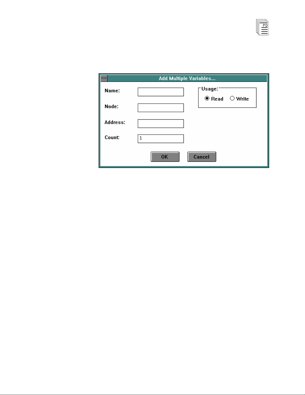
Add Multiple
The Add Multiple command allows you to add a number of MODBUS
variables to the MODBUS Master Function Block Editor window with a
single action. Choosing this command opens the dialog box shown in
Figure 4.
PD-6048 August, 96
(Issue 1)
13
Page 14
MODBUS Master Package for
W
INTERPRET
(T3837)
Figure 4. The Add Multiple MOD
BUS Variables Dialog Box
The variable parameters are as follows:
Name (Starting)
The name of the initial variable to be added. This is a required field and
must contain a valid W
Node
INTERPRET
tag name picture.
The MODBUS node to be associated with each MODBUS variable. This
required field must contain a valid MODBUS node number in the range of 1
-
247.
Address (Starting)
The starting MODBUS address to be used. This required field must contain
a valid MODBUS address in the range of 0 - 49,999. The specifi
address determines the MODBUS function to be used.
ed
PD-6048 August, 96
(Issue 1)
14
Page 15

MODBUS Master Package for
W
INTERPRET
(T3837)
Usage: Read/Write
The MODBUS function usage: to send data or receive data from a
MODBUS slave. This is a required field and must follow the MODBUS
variable type as implied by the MODBUS address.
Count
The number of MODBUS variables to be added. This required field must
contain a valid count in the range of 1 - 999.
Edit Parameters
This command allows you to specify or change the compile-time
configuration options for the MODBUS Master function bloc
this command opens the dialog box shown in Figure 5.
k. Choosing
The parameters are as follows:
Primary Port
The compile time parameter which selects the Regent serial port to be used
as the primary MODBUS port. This required field must be a valid port
PD-6048 August, 96
(Issue 1)
Figure 5. The MODBUS Parameters Dialog Box
15
Page 16

MODBUS Master Package for
W
INTERPRET
(T3837)
number in the range of 2 - 6, and must not be the same as the Secondary
Port field.
Secondary Port
The compile time parameter which selects the Regent serial port to be used
as the secondary MODBUS port. If not left
blank, this field must be a valid
port number in the range of 2 - 6, and must not be the same as the Primary
Port field.
Enable
The variable to be used as the ENABLE control relay. If not left blank, this
field must contain a valid W
Error
INTERPRET
tag name.
The variable to be used as the ERROR output coil. If not left blank, this
field must contain a valid W
INTERPRET
tag name.
Reset
The variable to be used as the ERROR output coil. If not left blank, this
field must contain a valid W
INTERPRET
tag name.
Error Code
The variable to be used as the [ERROR] CODE output register. If not left
blank, this field must contain a valid W
Error Node
INTERPRET
tag name
The variable to be used as the [ERROR] NODE output register. If not left
blank, this field must contain a valid W
MODBUS Scan Time
INTERPRET
tag name.
The variable to be uses as the [MODBUS Scan] TIME output floating
point register. If not blank, this field must contain a valid WINTERPRET tag
name.
MODBUS Scan Toggle
The variable to be uses as the [MODBUS
not blank, this field must contain a valid W
Search Menu
Scan] TOGGLE output coil. If
INTERPRET
tag name.
From the Search Menu (see Figure 6), you can select the Go To Variable,
Find, and Find Next commands.
PD-6048 August, 96
(Issue 1)
16
Page 17

MODBUS Master Package for
W
INTERPRET
(T3837)
Figure 6. The Search Menu
Go To Variable
The Go To Variable command allows you to quickly move to different
entries in the MODBUS variables list and the MODBUS parameters. After
choosing this command, the dialog box shown in Figure 7 opens.
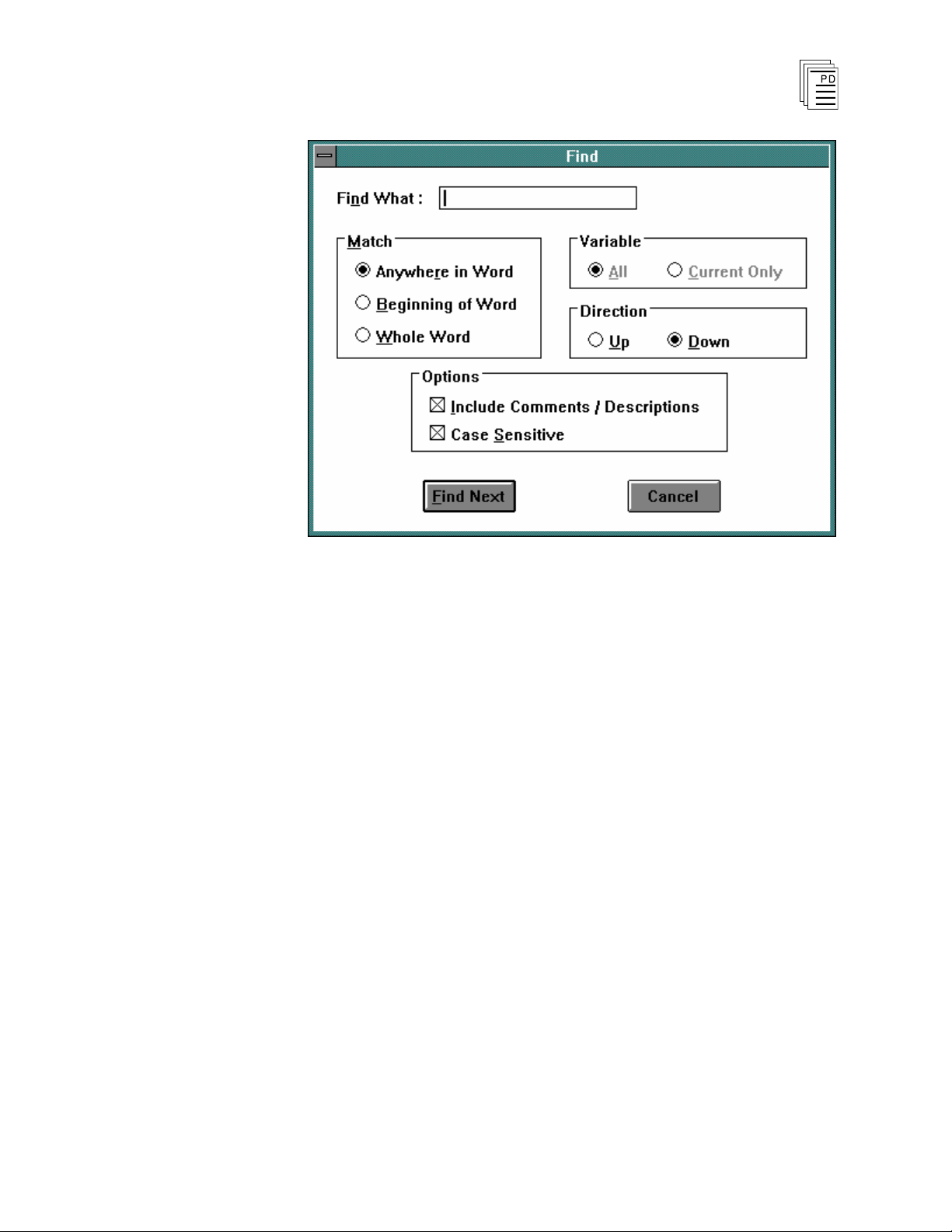
Find
The Find c
Figure 7. The Go To Variable Dialog Box
ommand allows you to locate different entries in the MODBUS
variables list and the MODBUS parameters. After choosing this command,
the dialog box shown in Figure 8 opens.
PD-6048 August, 96
(Issue 1)
17
Page 18
MODBUS Master Package for
W
INTERPRET
(T3837)
Find Next
Figure 8. The Find Dialog Box
The Find command searches for the next occurrence of whatever was
previously searched for using the Find command.
PD-6048 August, 96
(Issue 1)
18
Page 19

MODBUS Master Package for
W
INTERPRET
(T3837)
Using the MODBUS Master Function Block Monitor
The MODBUS Master function block monitor displays the parameters,
variables, addresses, and values of a MODBUS Master function bloc
executing in a Regent.
When you have selected a MODBUS Master function block in the
Program Monitor window and have chosen the Monitor command from the
Control Menu, the MODBUS Master Function Block Monitor Window is
opened, as shown in Figure 9.
Figure 9. The MODBUS Master Function Block Monitor Window
The MODBUS Function Block Monitor Window is essentially the same as
its editor counterpart except that no changes can be made to the variable
list, and the current value of each variable is displayed i
column.
n the left-most
k
File Menu
The File Menu provides access to several commands common to all
function block monitors, including View Function Block Details, View
Function Block Descriptions, Log Off, and Exit. For descriptions of these
commands, refer to
Monitors
PD-6048 August, 96
(Issue 1)
Commands Common to All Function Block
in Section 7 of the Regent
Ò
+ Plus User’s Guide.
19
Page 20

MODBUS Master Package for
W
INTERPRET
(T3837)
Control Menu
The Control menu provides access to several commands common to all
function block monitors, including Run, Sto
these commands, refer to
Monitors
The Control Menu command specific to the MODBUS Master Function
Block Monitor is the Take Monitor Offline command.
in Section 7 of the Regent Ò + Plus User’s Guide.
Take Monitor Offline
The Take Monitor Offline command allows you to toggle on and off the
constant update of the monitor with information from the Regent.
Search Menu
The Search menu allows you to perform standar
MODBUS Master function block. This menu is implemented exactly as
Search menu in the MODBUS Master Function Block Editor section of this
document.
Monitor Variable Dialog Box
p, and Scan. For descriptions of
Commands Common to All Function Block
d search operations on the
The MODBUS Variable Dialog Box (see Figure 10) is essentially the same
as that used in the editor, except that you cannot make any changes to the
variable definition, and the current value of each variable is displayed in a
separate field.
Figure 10. The MODBUS Master Monitor Parameter Dialog Box
PD-6048 August, 96
(Issue 1)
20
Page 21

MODBUS Master Package for
W
INTERPRET
(T3837)
Configur
Block
ing a MODBUS Master Function
Serial Port Definition
The MODBUS function block requires you to define a Regent serial port to
use as the primary and/or secondary MODBUS Master port. To allow the
user to reserve a port for this use, and so that the port definition can be
check at runtime a new type of serial port, called MOD MASTER, is used.
(This is a MODBUS master port type, but the current length restrictions
limit the length of port types to 10 characters.)
Serial Port List Dialog Box
From the Proj
display the Serial Port List Dialog Box (see Figure 11).
ect Editor "Definitions" menu, select Serial Ports. This will
The Type drop-down control now displays MOD MASTER between the
ASCII and MODBUS selections. The dialog box functions normally,
except that an additional validation rule is added for the MOD MASTER
port type.
PD-6048 August, 96
(Issue 1)
Figure 11. Serial Port List Dialog Box
21
Page 22

MODBUS Master Package for
W
INTERPRET
(T3837)
A MOD MASTER type port has the following restrictions:
·
8 data bits
·
2 stop bits an
d no parity bit, or 1 stop bit and 1 parity bit.
In addition, the Node field is not valid in this context, and is set to zero (0).
Figure 12. Serial Port Settings Dialog Box
Refer to Section 4 of the Regent Ò + Plus User’s Guide for more
information on working with serial ports.
PD-6048 August, 96
(Issue 1)
22
Page 23

MODBUS Master Package for
W
INTERPRET
(T3837)
Safety Considerations
The MODBUS Master function block is TÜV certified for Risk Class 5 as
non-interfering. These function blocks may only be used in safety
applications if they do not perform any control actions that affect the value
of Risk Class 5 safety critical variables.
Availability
The MODBUS Master function block is available as an add on package to
Winterpret/TRIOS versions 3.40 and later.
critical
PD-6048 August, 96
(Issue 1)
23
 Loading...