

Page 1

ICS Regent
®
PD-6044
Industrial Control Services
1
Continuous Control Package for
W
INTERPRET
Continuous Control Function Block for PID
Control (T3834)
Issue 1,
March, 06
The Continuous Control package for WINTERPRET
is an
add-in software package which allows the user to create
co
ntinuous control function blocks for Regent application
programs. When installed on the PC, the continuous
control package is seamlessly integrated with the base
W
INTERPRET
software.
Continuous Control is used to maintain a measured
process signal at a pr
edetermined value and provides the
user with three different control modes: Proportional,
Integral and Derivative. These modes give Continuous
Control the term ‘PID’. Each function block allows the user
to define up to 16 control loops (also known as con
trollers).
Software Installation
The Continuous Control package is installed on the PC
running the WINTERPRET
application software. The
W
INTERPRET base package provides the necessary
installation software to install this add-in package. The
Continuous Control package should be installed at the
same time or after you have installed the WINTERPRET
base package.
Installation Procedure
IMPORTANT!
The files on the Continuous Control package diskette are
in compressed form. You cannot simply copy the files to
your hard drive — they must be decompressed before they
will run. You must have the WINTERPRET
base package
Page 2

Continuous Control Package for W
INTERPRET
(T3834)
2
Industrial Control Services
distribution disk in order to run the setup procedure to
install the Continuous Control package.
To install the Continuous Control package, use the
following sequence:
1. Insert the WINTERPRET base package distribution disk
into drive A: or B:
2. Start Windows (if it isn’t already running).
3. Choose Run from the Program Manager’s File menu.
4. Type a:\
setup.exe
in the text box. (if you inserted the
W
INTERPRET base package disk in drive B: type
b:\setup.exe
.) Choose OK or press ENTER.
5. In the WINTERPRET Setup dialog box enter the name of
the directory in which you have installed the
W
INTERPRET base package (This assumes that you have
already insta
lled W
INTERPRET). Choose Continue.
6. In the WINTERPRET Installation dialog box check the
Continuous Control package box.
7. Choose OK to have the setup program install the
Continuous Control package software.
When the installation is completed, you can r
un the
W
INTERPRET application and create continuous control
function blocks in your application programs.
Working With Continuous Control (PID) Function Blocks
Application programs consist of one or more logical units
called function blocks. Each function
block performs part
of a program. These function blocks allow you to create
modular programs that are easily updated and
manipulated. Each function block can be used in one or
many programs.
Different types of function blocks can be combined to create
a
program.
Continuous control function blocks let you coordinate and
interlock the loop control functions with the discrete and
sequential functions of ladder logic. The shared variables
in the Regent provide a convenient way to do this.
Page 3

Continuous Control Package for W
INTERPRET
(T3834)
PD-6044
March, 06
3
Shared variables are data values internal to the Regent
that may be commonly referenced by all function blocks of
any application program. Use the Shared Variable Editor
to define the shared variables in the Regent.
Each controller may have up to 10 alarms associated with
it, each of which may be defined by assigning a name.
Continuous Control is used to maintain a measured
process signal at a predetermined value. A Continuous
Control process requires four fundamental items:
·
A process variable (PV) that can be measured
·
A s
etpoint (SP) at which the process variable should be
maintained
·
A control output that affects the process such that the
process variable is changed
·
A set of rules that govern how the controlled output
should be changed to make the process variable equal to
its setpoint
Most of the parameters in the Continuous Control loop
may be assigned a name instead of a constant value.
When a parameter is given a name, that value may be
dynamically modified by other application program
function blocks.
Examples of how
this dynamic modification might be used
include:
·
Assigning a name to the auto/manual parameter would
enable a ladder logic function block to place the
Continuous Control loop in automatic mode when
required by the process
·
Assigning a name to the setpoint p
arameter would
enable a ladder logic function block to modify the
setpoint automatically. Remote setpoint and ramp/soak
functions could be initiated automatically based upon
sequential process events.
·
Continuous Control alarms can be assigned names to
ena
ble them to be referenced in ladder logic function
blocks
Page 4

Continuous Control Package for W
INTERPRET
(T3834)
4
Industrial Control Services
Proportional Control
Making the controlled output a continuous variable that is
proportional to the process error provides a precise means
of controlling the process. The process error is the
diff
erence between the setpoint and the process variable.
This can be represented by:
Mn = P = Kcen
where,
Mn = controller output
P = proportional action
Kc = proportional constant, Gain
en = process error = setpoint (SP) - process variable (PV)
In practice this representation is not satisfactory because
the output is zero when the error is zero. Usually some
output is required to maintain the process variable at the
setpoint. This is called the output bias. The rules
governing the control output then become:
Mn = P + M
r
= Kcen + Mr
where,
Mr = output bias
With the addition of the output bias we have an output
value to keep the process variable at the setpoint. This
indicates that there is a finite controller output for a finite
process error. In many cases this finite value will not bring
the process variable back to the setpoint due to system
disturbances or setpoint changes. In effect, it becomes
necessary to continuously adjust or reset the output bias to
bring the process back in control.
Integral Control
The most common method used to automatically reset the
output bias is integral control. Integral control
automatically adjusts the output bias as long as there is a
process error. This is accomplished by integrating the error
with respect to time. The int
egral term can be expressed as:
In = I
n -1
+ (TS/Tl) * en
where,
n = current integral action
I
n-1
= previous integral action
Page 5

Continuous Control Package for W
INTERPRET
(T3834)
PD-6044
March, 06
5
TS = loop sample time
Tl = reset time
The amount of reset action is defined by the integral time
constant: reset time (Tl). The re
set time represents the time
required for the integral sum to equal the proportional
action. This assumes that the process error remains
constant. Thus a smaller value for reset time creates more
reset action. A larger value for reset time creates less res
et
action.
The integral term can be added to the equation to provide
an automatic reset function. When integral and
proportional control are combined the control output is
expressed as:
Mn = P+l+Mr = Kc [en + I
n-1
+ (TS/TI) * en] + Mr
Derivative Control
A
third type of control action is derivative control.
Derivative control causes the control output to change
based upon the rate of change of the error. It acts as an
anticipatory control action used to compensate for sudden
process changes or upsets. The derivative action can be
represented as:
Dn = (TD/TS ) * d
where,
Dn = derivative action
TD = derivative time constant, rate time
d = differential:
for error differential, de:
de = (en - e
n-1
)
where,
en = current error
e
n-1
= previous error
for process differential, dp:
dp = (PVn - PV
n-1
)
where,
PVn = current process variable
PV
n -1
= previous process variable
Page 6

Continuous Control Package for W
INTERPRET
(T3834)
6
Industrial Control Services
The amount of derivative action is defined by the
derivative time constant: rate time (TD). The rate time is
the time period over which the error rate of change is
extrapolated and a control action is based. A larger rate
time causes more derivative action. A smaller rate time
causes less derivative action. Derivative action is never
used alone but only in conjunction with proportional or
bo
th proportional and integral. When derivative control is
combined with proportional control and integral control,
the output equation is expressed as:
Mn = Kc [en + In
-
1
+ (TS/Tl) * en + (TD/TS) * de] + M
r
Often all three control modes are used. This three-mode
control is referred to as PID control, which has been widely
accepted as a general set of rules suitable for most
continuous control systems. The PID algorithm can be
"tuned" to reflect the unique dynamics of a particular
process by modifying the proportional, integral and
derivative constants (gain, reset time and rate time) until
the desired system response is achieved.
Page 7
Continuous Control Package for W
INTERPRET
(T3834)
PD-6044
March, 06
7
Using the Continuous Control (PID) Editor
Continuous Control function blocks are created using Add
Function Block or Insert Function Block from the Program
Editor. After you have created a new function block the
Continuous Control Editor window is opened as shown in
Figure 1.
Figure 1. The Continuous Control (PID) Editor Window.
The Continuous Control Editor lets you create an
d edit
continuous control function blocks. When you create a
continuous control function block you will enter your
parameters in the dialog boxes.
It should be noted that output and output bias variables
must be unique to a controller.
Using drop-down
menus you can select commands to
configure controllers in the function block, print the
function block and perform a host of other options.
Page 8

Continuous Control Package for W
INTERPRET
(T3834)
8
Industrial Control Services
File Menu
The File Menu gives you access to the standard function
block file commands which include: Save Function
Block,
Revert to Last Saved, Compile, View Error Messages, Edit
Function Block Description, Edit Function Block Details,
Print Function Block, Print Setup, Log Off and Exit. For
more information on all of these commands refer to
Commands Common to all Function Blocks in Section 5 of
the Regent User’s Guide.
Edit Menu
From the Edit Menu the user can select the Add
Controller, Edit Controller, Insert Controller and Delete
Controller commands.
Add Controller/Insert Controller
The Add Controller command lets you add a controller to
the function block. The new controller is added at the end
of the list. The Insert Controller command lets you add a
new controller to the function block. The new controller is
inserted just above, or before, the selected controller.
After choosing Add or Insert Controller, the dialog box
shown in Figure 2 will open. The Controller dialog opens
with the default values shown.
Page 9

Continuous Control Package for W
INTERPRET
(T3834)
PD-6044
March, 06
9
Figure 2. Add/Insert Controller Dialog Box
The PID controller parameters are as follows:
Page 10

Continuous Control Package for W
INTERPRET
(T3834)
10
Industrial Control Services
Low Scaling Va
lue
The low engineering value corresponding to the analog
value of 0. The low scaling value must always be less than
the high scaling value (-32768 < x < high scaling value).
PID Controller Name
The name of the control loop. Follows the same format as
ta
g names. The controller name must not be the name of a
variable.
PID Controller Title
A controller may be given a title containing up to 40
characters of descriptive text. This is the only optional
parameter for a controller.
Input
The name of the process variable which is to be maintained
at the desired setpoint.
High Scaling Value
The high engineering value corresponding to the analog
value of 4,095. The high value must always be greater
than the low value (low scaling value < x < 32767).
Scaling Type
Choose the Linear option button for linear value
conversion. Choose the Square Root option button for
square root extraction (square root extraction is typically
used to linearize flow signals that are measured using
differential pressure transmitters).
O
utput
The name of the variable which receives the result of the
current control computation.
Output Bias %
The bias portion of the control loop. May be in the range
0.0 to 100%. The default value is 0.0%. The corrective
output that maintains the output
at the setpoint.
Output Delta %
The maximum change of output allowed between two loop
calculations. May be in the range 0.0 to 100%. The default
value is 100%.
Page 11

Continuous Control Package for W
INTERPRET
(T3834)
PD-6044
March, 06
11
Direct/Reverse (Control Direction)
Determines the control output gain. In Direct mode, the
c
ontrol output increases as the gain increases (direct acting
or positive gain). In Reverse mode, the control output
decreases as the gain increases (reverse acting or negative
gain). The default value is Direct.
Sample Time
The sample time is the time be
tween loop calculations to
determine how often the controller is solved. May be in the
range 0.01 to 650 seconds. The default value is 1.00 second.
Gain
The gain constant value, including the process gain and
the controller gain. May be in the range 0.01
to 50
(unitless). The default value is 1.00. The desired ratio of
change in corrective action for a given change in the error.
Reset Time
The reset time is the time required to eliminate the effects
of offset introduced by the proportional term. May be
in
the range 0.0 to 3600 seconds. The default value is 0.0
seconds.
Rate Time
The rate time is the time required for the derivative action
to advance the effects of the proportional action. A value of
0 disables the computation of the derivative compone
nt.
May be in the range 0.0 to 250 seconds. The default value
is 0.0 seconds.
Setpoint
The setpoint at which the process value is maintained.
May be in the range Setpoint Low < x < Setpoint High.
There is no default value.
Setpoint Low Limit
The setpoint low limit is the smallest value that the
setpoint can become from the actions of bumpless transfer
or cascade. May be in the range Scale Low < x < Setpoint
High. There is no default value.
Page 12

Continuous Control Package for W
INTERPRET
(T3834)
12
Industrial Control Services
Setpoint High Limit
The setpoint high limit is the largest va
lue that the
setpoint can become from the actions of bumpless transfer
or cascade. May be in the range Setpoint Low < x < Scale
High. There is no default value.
Setpoint Tracking
Select Yes or No. If Yes is selected, the setpoint becomes
the process var
iable value upon mode change from manual
to automatic (bumpless transfer). If No is selected, the
setpoint remains unchanged upon mode change from
manual to automatic. The default value is Yes.
Low Integral Windup %
The lower limit on the control loop ou
tput (%) where
integral windup is prevented. May be in the range 0.0 to
100%. The default value is 0.0%. The smallest value for
the integral error. The integral sum is not updated for
values smaller than the limit.
High Integral Windup %
The upper limit on the control loop output (%) where
integral windup is prevented. May be in the range 0.0 to
100%. The default value is 100%. The highest value for
the integral error. The integral sum is not updated for
values larger than the limit.
Auto/Manual (Oper
ational Mode)
Loop calculation. In Manual, loop calculation is not
performed (ie. the controller is driven by the operator). In
Automatic, loop calculation is performed (ie. The controller
is driven by the Regent PID algorithm). The default value
is Man
ual.
Automatic On
(Yes/No) Controls the master control loop switching. If Yes
is selected, the master control loop of a cascaded system is
switched to automatic when the slave control loop is in
automatic mode. The default value is Yes.
Maximum Error
The
maximum error value allowed for the loop calculation
(in engineering units). May be in the range 0 < x < Scaling
Range. There is no default value. The largest value for
the error for any sample of the process variable.
Page 13

Continuous Control Package for W
INTERPRET
(T3834)
PD-6044
March, 06
13
Error Rate
The maximum rate of change of error allowed for the loop
calculation (in engineering units). May be in the range 0
<
x < Scaling Range. There is no default value.
Differential
Applicable only to the derivative term, calculations may be
based on Error or Process differential
. The default value is
Error.
Error SQR P
Enables proportional action to be based on error (No) or
error squared (Yes). The default value is No.
Error SQR I
Enables integral action to be based on error (No) or error
squared (Yes). The default value is No.
Error Deadband
The distance above and below the setpoint for which the
error is ignored (in engineering units). May be in the
range 0 < x < Scaling Range. There is no default value.
Simple/Mod (Error Mode)
Determines the way in which the error within the
deadband is treated. In Simple mode, the error is treated
as zero for P, I and D terms. In Modified mode, the error is
treated as zero for P and D terms and Integral action is
calculated using the error value. The default value is
Simple
Low Deviation
The smallest change about the setpoint that causes a
warning alarm (in engineering units). May be in the range
0 < x < Deviation High. There is no default value.
High Deviation
The largest change about the setpoint that causes a
warning alarm (in engineering units). May be in the range
Deviation Low < x < Scaling Range. There is no default
value.
Page 14

Continuous Control Package for W
INTERPRET
(T3834)
14
Industrial Control Services
The Alarms dialog is launched from the Controller dialog
by pressing the ‘Alarms...’ button. All alarms are optional if required, an alarm is specified by entering a variable
name. The same name may be used for alarms in different
controllers within a function block, but a warning message
will be displayed on compilation.
Figure 3. The Continuous Control (PID) Alarms
Dialog Box.
The PID alarms are a
s follows:
Page 15

Continuous Control Package for W
INTERPRET
(T3834)
PD-6044
March, 06
15
Low Integral Windup Alarm
On if the integral error is smaller than the low integral
value.
High Integral Windup Alarm
On if the integral alarm error is larger than the high
integral value.
Maximum Error Alarm
On when the error term is larger than the maximum error.
Maximum Error Rate Alarm
On when the rate of change for the error exceeds the
maximum error rate.
Setpoint Low Alarm
On when the setpoint is lower than the setpoint low limit.
Setpoint High Alarm
On when the setpoint is higher than the setpoint high
limit.
Deviation Low Alarm
On when the change about the setpoint is smaller than the
deviation low limit.
Deviation High Alarm
On when the change about the setpoint is larger than the
deviation high limit.
Negative Deviation
On to indicate
the controller output is decreasing.
Control On Status
On to indicate that the control loop is running in automatic
mode, off to indicate that the control loop is running in
manual mode or algorithm cannot be calculated in
automatic mode.
Edit Controller
T
he Edit Controller command lets you edit a controller.
The Edit Controller command brings up the same dialog as
add/insert controller, but with the values filled in.
Delete Controller
The Delete Controller command deletes a controller from
the function bl
ock.
Page 16

Continuous Control Package for W
INTERPRET
(T3834)
16
Industrial Control Services
Search Menu
From the Search Menu the user can select the Go to
Controller, Find and Find Next commands.
Go To Controller
The Go to Controller command lets you quickly move to
different entries in the controller list.
Figure 4. Go to Controller Dia
log Box
Entry Number:
Enter the controller number that you want to go to.
Go:
Choose Go to move to the controller number that you
entered in the Entry Number text box.
First:
Go to the first controller in the list.
Last:
Go to the last controller i
n the list.
Page 17

Continuous Control Package for W
INTERPRET
(T3834)
PD-6044
March, 06
17
Find
The Find command can be used to locate variables in the
controller list.
Figure 5. The Find Dialog Box
Find What text box:
Type in the source name of the entry or character string
you want to search for. The Find What text box ret
ains the
name of the last entry or character string that was
searched for. Use the Find Next command button or press
F3 to repeat the search.
Match:
Lets you to match character strings as they occur
anywhere in a word, only at the beginning of a word, o
r as a
whole word.
Direction:
Determines whether the search will move upward or
downward from the current function block. The search will
stop when it reaches either the top or the bottom of the list.
Options:
The Options check boxes let you decide wh
ether to search
for the character string in the entries' comments and
Page 18

Continuous Control Package for W
INTERPRET
(T3834)
18
Industrial Control Services
descriptions and whether the search should be case
-
sensitive.
Find Next
The Find Next command searches for the next occurrence
of whatever name (or character string) was previously
searc
hed for using the Find command.
Options Menu
The Options Menu allows you to enable and disable the
Prompt for Delete option common to all delete operations
used in W
INTERPRET
.
Window Menu
The Window menu commands are standard throughout all
W
INTERPRET
wind
ows. For more information on using the
Window menu commands see Commands Common to all
W
INTERPRET Windows in Section 3, Installing the
W
INTERPRET Application of the Regent User’s Guide.
Help Menu
The Help menu commands are standard throughout all
W
INTERPRET windows. For more information on using the
Help menu commands see Commands Common to all
W
INTERPRET Windows in Section 3, Installing the
W
INTERPRET Application of the Regent User’s Guide.
Page 19

Continuous Control Package for W
INTERPRET
(T3834)
PD-6044
March, 06
19
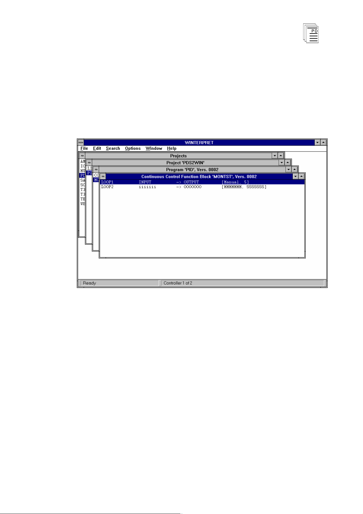
Using the Continuous Control (PID) Monitor
The Continuous Control (PID) Monitor displays the
current status of the continuous control function block
defined in your system.
When you have selected a Continuous Control function
block in the Program Monitor window and chosen the
Monitor command from the Control Menu, the Continuous
Control Monitor window is opened as shown below.
Figure 6. Continuous Control Monitor Window.
File Menu
The File Menu provides access to several commands
common to all function block monitors. These include View
Function Block Details, View Function Block Description,
Log Off and Exit. For descriptions of these commands see
Commands Common to all Function Block Monitors in
Section 7, Loading, Monitoring and Testing Application
Programs in the Regent User’s Guide.
Page 20

Continuous Control Package for W
INTERPRET
(T3834)
20
Industrial Control Services
Control Menu
The Contro
l Menu provides certain commands that are
common to all function block monitors. These include Run,
Stop and Scan commands to control the execution status of
the entire application program. For descriptions of these
commands see Commands Common to all Function Block
Monitors in Section 7, Loading, Monitoring and Testing
Application Programs in the Regent User’s Guide.
Control Menu commands which are Continuous Control
specific are: Tune Controller and Monitor Controller.
Tune Controller
The Tune Controller command displays the dialog box
shown in Figure 7. All parameters for the controller are
displayed. For parameters which have been defined as
constants, only the constant value is displayed. For
parameters which have been defined as variables, the
v
ariable name is displayed in the right hand field and the
continuously updated value of the variable obtained from
the Regent is displayed in the left hand field. Due to the
size of the dialog, the full dialog cannot be seen on systems
with VGA resolution. The Windows ‘move window’ facility
can, however, be used to move the dialog around the screen
to view different sections.
Figure 7. Tune Controller Dialog Box.
Page 21

Continuous Control Package for W
INTERPRET
(T3834)
PD-6044
March, 06
21
Note: In order to tune a controller while it is running in a
Regent, each parameter to be tuned should be defined as a
variable (shared variables may be defined with initial
values, local variables may not). The Data Monitor should
be used to change the values of the variables as required.
Monitor Controller
The Monitor Controller command displays the dialog box
shown in Figure 8. In order that the whole dialog can be
viewed on systems with VGA resolution, this dialog
displays only ‘key’ variables.
Figure 8. Monitor Controller Dialog Box.
Search Menu
The Search Menu provides commands to locate
information in a continuous controller function block. You
can choose Go to Controller (to move to a particular control
loop), Find (to search for text strings) or Find Next (to
repeat the last Find selection).
Page 22

Continuous Control Package for W
INTERPRET
(T3834)
22
Industrial Control Services
Window Menu
The Window menu commands are standard throughout all
W
INTERPRET windows. For more information on using the
Window menu commands see Commands Common to all
W
INTERPRET Windows in Section 3, Installing the
W
INTERPRET Application of the Regent User’s Guide.
Help Menu
The Help menu commands are standard throughout all
W
INTERPRET windows. For more information on using the
Help menu commands see Commands Common to all
W
INTERPRET Windows in Section 3, Installing the
W
INTERPRET Application of the Regent User’s Guide.
Safety Consideration
s
The continuous control function block is TÜV certified for
Risk Class 5 as non-interfering. These function blocks may
only be used in safety critical applications if they do not
perform any control actions that affect the v
alue of Risk
Class 5 safety critical variables.
Page 23

Continuous Control Package for W
INTERPRET
(T3834)
PD-6044
March, 06
23
 Loading...