

Page 1

ICS Regent
®
PD-6041
Communications Package for
W
INTERPRET
Guarded Peer-Link Communications
(T3831)
Issue 1,
The W
ware package that allows you to configure Guarded Peer-Link
communications for interconnected Regent systems. Using
Guarded Peer-Link, multiple Regent systems can transfer
safety-critical data between each other for distributed safety
interlocking within a plant. Using redundant networks and
communications modules, the peer-to-peer communications
are protected against single points of failure.
INTERPRET Communications Package is an add
March, 06
-
in soft
-
Features
·
Multidrop peer-to-peer communications between two to 31
Regent controllers.
·
Supports single and redundant networks
legs).
·
Deterministic protocol suitable for transfer of safety-critical
data between Regent systems.
·
TÜV certified, Risk Class 5.
·
Transfer up to 6,500 variables over the network.
·
Each leg of a redundant network is Mastered by a separate
Regent system.
·
Full status monitoring and alarming of the network through
system variab
(from one to five
les in each Regent.
Industrial Control Services
1
Page 2

Communications Package for
Important!
W
INTERPRET
(T3831)
Software Installation
The Communications package is installed on the PC running
the WINTERPRET
package provides the necessary installation software to install
this add-in communications package. The communications
package should be installed at the same time or after you
have installed the WINTERPRET
Installation Procedure
The files on the Communications package diskette are in
compressed form. You cannot simply copy
hard drive — they must be decompressed before they will run.
You must have the WINTERPRET base package distribution
disk in order to run the setup procedure to install the
Communications package.
To install the Communications package, use the following
sequence:
1. Insert the WINTERPRET base package distribution disk into
drive A: or B:
application software. The W
base package.
the files to your
INTERPRET
base
2. Start Windows (if it isn’t already running).
3. Choose Run from the Program Manager’s File menu.
4. Type a:\
W
INTERPRET base package disk in drive B: type
b:\setup.exe
5. In the WINTERPRET Setup dialog box enter the name of the
directory in which you have installed the WINTERPRET
base package (This assumes that you have already
installed WINTERPRET). Choose Continue.
6. In the WINTERPRET Installation dialog box check the
Communications package box.
7. Choose OK to have the setup program install the
Communications package software.
When the installation is completed, you can run the
W
INTERPRET application and define the Guarded Peer
communications variables and projects. For detailed
guidelines on configuring the Guarded Peer-Link
setup.exe
.) Choose OK or press ENTER.
in the text box. (if you inserte
d the
-
Link
2
Industrial Control Services
Page 3
Communications Package for
communications see Configuring the Guarded Peer-Link,
starting on page 11.
W
INTERPRET
(T3831)
Guarded Peer-Link Operation
Guarded Peer-Link communications allow multiple Regents to
send and receive data over a bussed serial communications
network. This multidrop network can be made redundant by
using up to five separate multidrop legs, ea
serial ports on the Regent communications modules. An
example is shown in Figure 1.
ch connected to
PD-6041
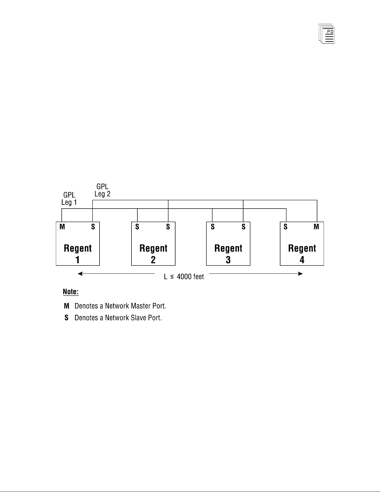
Figure 1. Guarded Peer-Link Communications Network.
Each leg of the GPL network requires one Regent to act as the
GPL Master for the leg. When redundant legs are used for
fault tolerance, each leg has a unique GPL master. For
example, in Figure 1, Regent 1 is the GPL master for network
leg 1 and Regent 4 is the GPL master of network leg 2. By
utilizing separate GPL masters for each network leg, the GPL
communications can be maintained as long as at least one
March, 06
GPL master is running.
3
Page 4
Communications Package for
W
INTERPRET
(T3831)
Theory of Operation
Each leg of the GPL network uses a bussed multidrop RS-485
communication link for exchanging data between up to 31
Regents. When loaded and operating, the GPL
communications activity on each leg sequences through
polling commands and broadcast responses as shown in
Figure 2. The completion of this sequence for each Regent on
the network makes up a GPL communications cycle. This
cycle repeats continuously while the GPL master for the leg is
operating. Each leg of the network runs asynchronous to each
other.
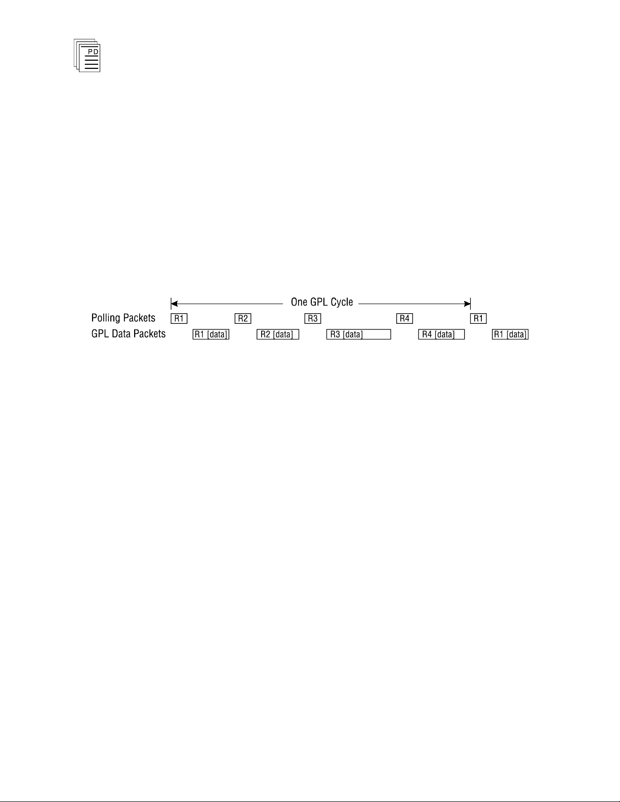
Figure 2. The GPL communications cycle.
During the communications cycle the GPL master issues a
poll command to a Regent to transmit its GPL data packet.
The polled Regent broadcasts its GPL data packet which
contains all of the GPL variables configured for the Regent.
Each Regent on the network receives the broadcasted GPL
data packet and stores the contents in an internal GPL input
buffer. The GPL master then issues a poll command to the
next Regent on the network to transmit its GPL data packet.
This sequence continues until all Regents identified in the
GPL configuration have been polled and subsequently
broadcast their GPL data packets. The GPL master repeats
the communication cycle continuously.
Internal to each Regent configured for GPL communications
are input templates, output templates, input data buffers and
output data buffers. Each of these are described below.
Input Templates
The Regent has an input template for every configured node
on the network (including itself). Figure 3 illustrates the
structure of the GPL input templates for each Regent
configured for Guarded Peer-Link communications.
4
Industrial Control Services
Page 5
Communications Package for
W
INTERPRET
(T3831)
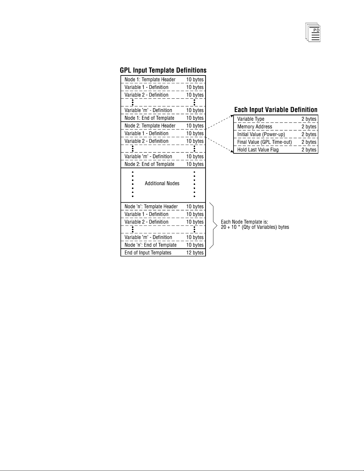
Figure 3. Structure of the GPL Input Templates.
The input templates allow the Regent to understand the data
format of GPL variables from each Regent’s data packet and
where to copy the needed variables from the input buffers into
this Regent’s I/O and shared variables. In addition, the input
template contains initial and final values for each variable (as
configured in the I/O or shared variable editors). The initial
value will be used when the Regent powers up (warm starts),
until subsequent GPL data packets are received. The final
valu
e is used for input variables when input data is not
received from a particular node on the network (all of the
input buffers for the node have timed out on all legs, see GPL
Fault Handling, starting on page 8).
The total size of the GPL input template in each Regent will
be:
GPL Input Template = 20 * (No. of Nodes) + 10 * (Qty of Variables) + 12 bytes
PD-6041
March, 06
5
Page 6
Communications Package for
W
INTERPRET
(T3831)
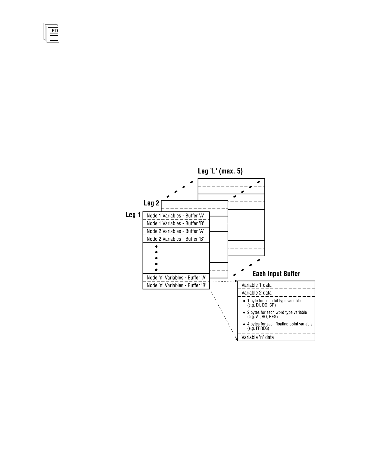
Input Data Buffers
Each Regent connected to a GPL network with “L” legs has
2*L input data buffers for each node on the network
(including itself). For example a GPL network with two legs
(dual redundant) has 4 input data buffers for each node (two
for each leg). Each of these data buffers is the size of the GPL
data packet from the associated node. Figure 4 illustrates the
structure of the GPL input data buffers in each Regent
configured for Guarded Peer-Link communications.
6
Figure 4. Structure of the GPL Input Data Buffers.
When an incoming GPL data packet is received it is stored in
one of the two buffers for the leg of the network the data was
received and the input data buffer is marked as “most recent.”
The previous “most recent” input data buffer is marked as
“empty.” At the end of the application program scan, the
Regent will use the input data buffer that is marked as most
Industrial Control Services
Page 7
Communications Package for
W
INTERPRET
(T3831)
recent to transfer the input GPL variables into the Regent’s
shared variables and I/O memory areas (as defined by the
input templates).
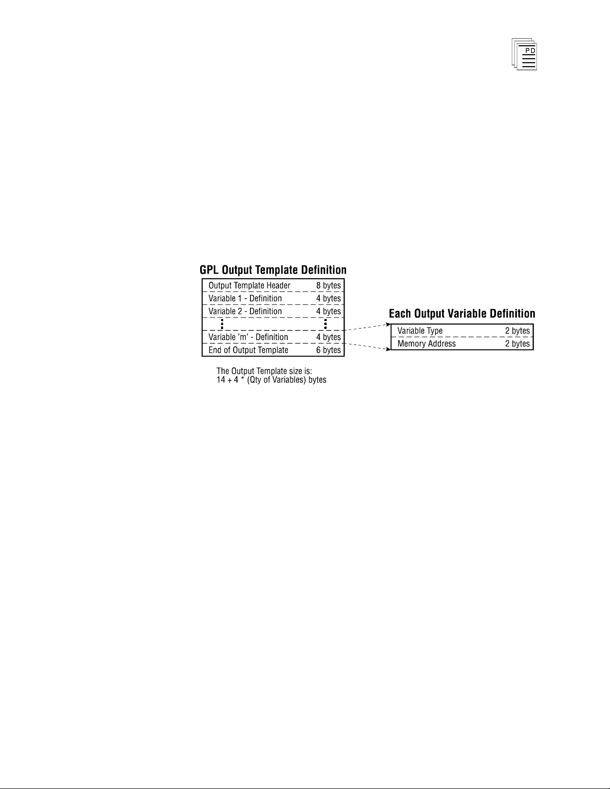
Output Template
The Output Template is used to identify which variables in
the Regent are configured as GPL variables that this Regent
provides to the GPL network. Figure 5 illustrates the
structure of the GPL output template for an individual
Regent configured for Guarded Peer-Link communications.
Figure 5. Structure of the GPL Output Template.
At the end of each application program scan the Regent uses
the definitions in the output template to load its primary GPL
output data buffer with the GPL output variables.
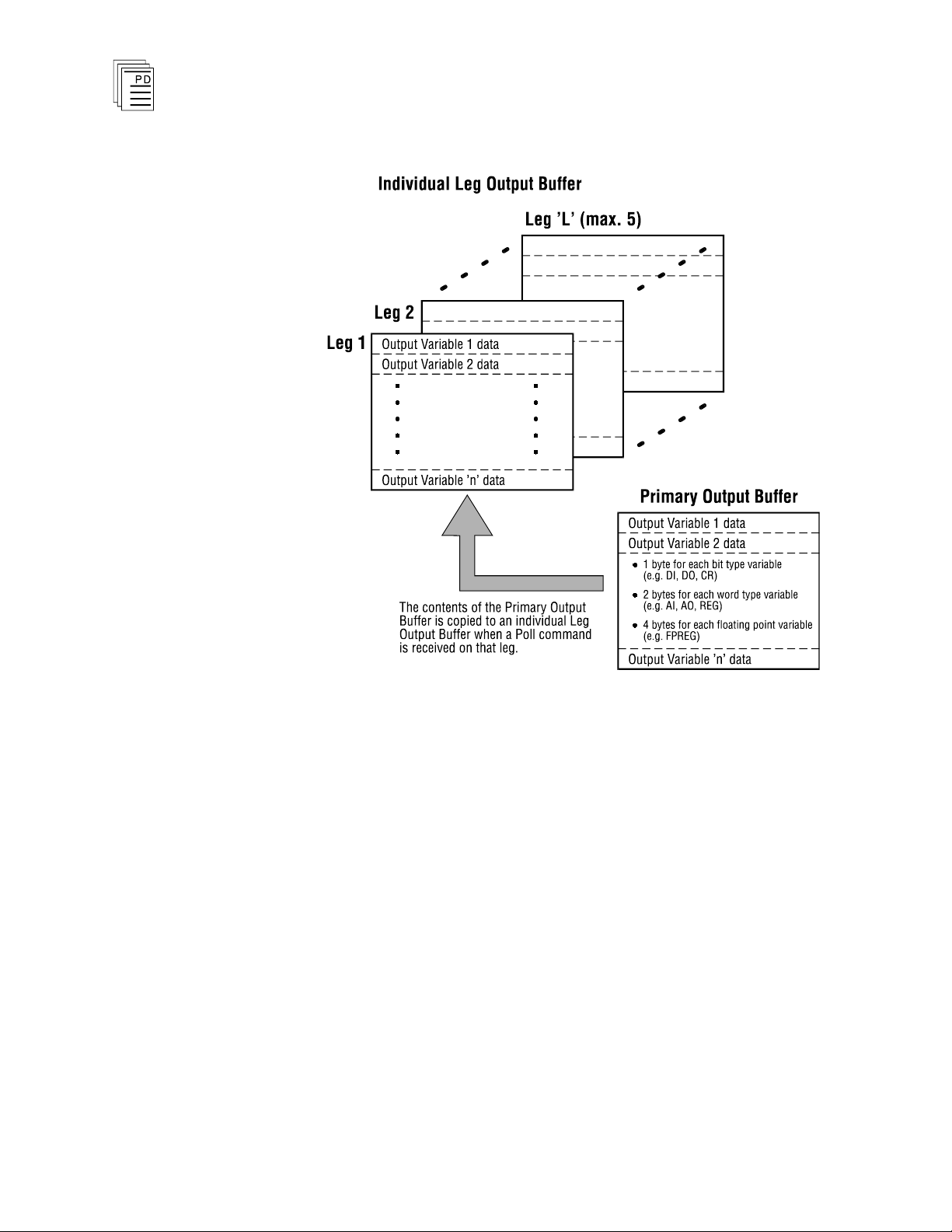
Output Data Buffers
Each Regent connected to a GPL network with “L” legs has
L+1 output data buffers. One is a primary output data buffer
and the others are individual output data buffers for each leg
of the network. Figure 6 illustrates the structure of the GPL
output data buffers for a Regent configured for Guarded Peer
Link communications.
-
PD-6041
March, 06
7
Page 8
Communications Package for
W
INTERPRET
(T3831)
Figure 6. Structure of
the GPL Output Data Buffers.
Each buffer is the size of the GPL data packet that this
Regent provides to the network. At the end of each
application program scan, the values of the variables
configured for GPL are copied into the primary output data
buffer. When the Regent receives its GPL poll command from
a particular leg of the network, the primary output data buffer
is copied to the output data buffer for that leg and the Regent
broadcasts its GPL data from this buffer to the particular leg
of the net
GPL Fault Handling
work.
During GPL operations, each Regent performs fault detection
and fault handling for the GPL communications, regardless of
whether it is a GPL Net Master or Net Slave. The input
8
Industrial Control Services
Page 9

Communications Package for
Communications Error
Explanation
Parity
The communications module UART detects a
parity error for character.
Framing
The communications module UART detects a
data framing error.
Character over-run
The communications module UART detects a
character over-run.
Packet CRC
The Regent validates the CRC for a received
packet.
Intercharacter time-out
The Regent detects an intercharacter time-out
condition (5 character times).
Packet echo time-out
The Regent detects that a node has not started
to transmit a response to a poll request in the
allotted time (20 milliseconds).
Remote activity time-out
The Regent reports an error when no
communications activity occurs on a GPL port for
allotted time (2 seconds).
W
INTERPRET
(T3831)
templates in each Regent provide a complete definition of the
entire GPL network configuration.
When the GPL communications are active (see Connect
Network, starting on page 22) each Regent monitors the
activities of the GPL network for the types of errors listed in
Table 1. A brief explanation accompanies each type of error.
When the Regent detects errors on the GPL communications,
it reports these errors using system variable control relays.
Internally the Regent filters these faults to mask
intermittent failures. When a fault occurs repeatedly, then
fault bits are set and certain fault handling responses may
occur.
Table 1. Guarded Peer-Link Communications Errors.
transient or
PD-6041
March, 06
For example if a Regent fails to receive data from a particular
node on the network, a fault bit will be set and the GPL input
data variables associated with that node will be set to their
configured final values.
GPL System Variables
There are 49 system variable control relays that are defined
for GPL status and fault reporting. These variables should be
monitored as appropriate in the application programs or
operator interface to notify plant personnel about the status of
9
Page 10

Communications Package for
Variable Name
Description
GPLPxMASTER
Port x is configured as a GPL Net Master Port — x
is
the port number (2 through 5). This bit turns on after
loading the Regent serial ports definition.
GPLMSTRSCAN
The GPL master is scanning. If the Regent is
configured as a GPL Net Master, this bit is on after the
Start Network command is performed.
GPLCONNECT
The Regent is connected to GPL. Once the Connect
Network command is performed, this bit is on to
indicate the GPL Network functions are active.
GPLINTEMP
The GPL input template is defined. This bit is on after
the Load Network command is performed, to indicate a
valid input template is loaded.
GPLOUTTEMP
The GPL output template is defined. This bit is on after
the Load Network command is performed, to indicate a
valid output template is loaded.
GPLSCANONE
First GPL scan. This bit is on after the Connect
Network command is first performed and remains on
until several GPL communications cycles have
completed successfully.
GPLDATAxx
GPL Node xx has provided fresh data — xx
ranges from
01 to 31. When GPL is successfully running, the
GPLDATAxx bit is on for each configured GPL node.
While the GPL is running, if a GPLDATAxx bit turns off,
it indicates that this Regent is no longer rece
iving fresh
data from node xx.
GPLFLTANYBUS
Fault on any GPL bus. This bit turns on if any type of
fault is detected for GPL. Normally accompanied by
GPLPxFAULT bit(s).
GPLPxFAULT
Port x GPL bus fault. This bit turns on if a fault is
detected for a specific communications port for GPL —
x ranges from 1 to 6, representing the communications
port number of the Regent.
GPLFLTLOCAL
GPL local bus has a fault. This bit turns on when the
Regent detects a local fault using a loopback
verification test when i
t transmits its own GPL packets.
Normally this fault indicates a communications module
fault, or cable disconnected.
GPL communications. A brief description of each of these
variables is provided in Table 2.
W
INTERPRET
(T3831)
Table 2. GPL System Variables.
10
Industrial Control Services
Page 11

Communications Package for
W
INTERPRET
(T3831)
Configuring the Guarded Peer-Link
Configuration Planning
The Guarded Peer-Link Definitions Dialog is accessed from
the Project Selector Window’s Definitions Menu. Before you
use this command you should perform the following activities.
1) Define all Projects
Each Regent to be connected using Guarded Peer-Link
communications must be defined as a project using
W
INTERPRET
2) Configure the se
For each Regent, configure the serial ports that will be
used for Guarded Peer-Link communications. For each leg
of the Guarded Peer-Link, one Regent will be configured
with a Net Master port and the other Regents will be
configured with a Net Slave port.
3) Identify the GPL variables provided by each Regent
.
rial ports
Each variable that a Regent will provide to one or more
other Regents must be already be defined in the providing
Regent’s I/O or shared variable definitions.
4) Identify the GPL variables received by each Regent
Each GPL variable that a Regent will receive from another
Regent must be defined in the receiving Regent’s I/O or
shared variable definitions. In the receiving Regent’s I/O
or shared variable definition the variable must be defined
using the exact same tag name the variable is named in
the providing Regent.
PD-6041
March, 06
11
Page 12

Communications Package for
Configuring the Regent Serial Ports for GPL
W
INTERPRET
(T3831)
Communications
In each Regent project, use the Serial Ports command from
the Project Editor’s Definitions Menu to define the serial p
orts
used for GPL communications. An example of the Serial Ports
dialog is shown in Figure 7.
Figure 7. Defining GPL Ports in the Serial Ports Dialog.
In this example, two ports are configured for GPL
communications indicating that the GPL network uses two
legs for redundancy. Port 2 is configured as a Net Master for
one leg — all other Regents connected to this leg should be
configured as Net Slaves. Port 4 is configured as a Net Slave
—
one of the other R
Master for this leg of the GPL Network.
egents must be configured as the Net
Each GPL port for this Regent is configured as node number
1, and the baud rate is set for 19,200 baud. Data format for
GPL ports must be set for 8 data bits, 1 stop bit and odd
parity.
An example of the serial port settings for four Regents
connected by two legs of a GPL network is shown in Table 3.
12
Industrial Control Services
Page 13

Communications Package for
Port
#
Node
#
Port Type
Baud
Rate
Data
Format
Network
Leg
Regent
1
2
4
1
1
Net Master
Net Slave
19.2K
19.2K
8+1+Odd
8+1+Odd
1
2
Regent
2
2
4
2
2
Net Slave
Net Slave
19.2K
19.2K
8+1+Odd
8+1+Odd
1
2
Regent
3
4
6
3
3
Net Slave
Net Slave
19.2K
19.2K
8+1+Odd
8+1+Odd
1
2
Regent
4
3
5
4
4
Net Slave
Net Master
19.2K
19.2K
8+1+Odd
8+1+Odd
1
2
W
INTERPRET
(T3831)
Table 3. Example of Serial Port Settings for Four Regents.
In this example, each Regent has a unique node number, and
both GPL ports for an individual Regent are assigned the
same node number. For each Regent, the two ports used for
GPL communications are ports on different communications
modules. This makes the network fault tolerant in case of a
communications module failure and subsequent module
removal and replacement. In the example, Regent 1 is the
Net Master for Leg 1 of the GPL network and Regent 4 is the
Net Master for Leg 2. All other GPL ports are configured as
Net Slaves. The Baud rate and data format are configured
the same for all GPL ports.
PD-6041
March, 06
Identifying GPL variables
An example of variable definitions for four Regents is shown
in Table 4. The variables listed in each Regent’s column
would need to be defined in the I/O or shared variable
definitions for that Regent.
For each Regent, the variables are arranged in two rows to
illustrate whether the Regent will output the variables to the
GPL network (to one or more other Regents), or whether the
Regent will input the variables from the GPL network (from
another Regent).
13
Page 14

Communications Package for
Regent 1
Regent 2
Regent 3
Regent 4
GPL
Output
Variables
LS101_R1
XV118_R1
LT172_R1
PB100_R1
PT219_R2
PT308_R3
LT342_R3
LT356_R3
[none]3
GPL
Input
Variables
PT219_R2
PT308_R3
PB100_R1
XV118_R1
[none]2
LT172_R1
LT342_R3
LT356_R3
PB100_R1
W
INTERPRET
(T3831)
Table 4. Example of Variable Definitions.
Notes:
1) Choose a format for the tag names that you will use for
GPL variables. For example, the last three characters of
each tag name (e.g.
_R1, _R2, _R3 or _R4) were chosen to
indicate which Regent originates the variable to the GPL
network. This type of tag name format is not required but
it helps identify th
and other plant personnel.
e GPL variables to system engineers
2) A Regent might only output data to the GPL network. For
example, Regent 3 outputs three variables to the GPL
network. However, it doesn’t have any definitions for the
variables that are output by the other Regents. The GPL
data received from the other Regents will not be used by
Regent 3.
3) A Regent might only input data from the GPL network.
For example, Regent 4 doesn’t output any variables to the
GPL network. However, it has four variables defined that
will be input from the GPL data of the other Regents.
You should plan for the GPL configuration by making sure
that each Regent has an identical tag name defined (typically
in its shared variable definition) for every variable it will need
to receive from another Regent.
Initial and Final Values
When you configure variables in the I/O and shared variable
definition editors, you can configure an initial and final value
for each variable (except digital and analog inputs). These
14
Industrial Control Services
Page 15

Communications Package for
W
INTERPRET
(T3831)
values are used by the GPL configuration when building the
input data templates for each Regent.
The initial value is used after a Regent warm starts until a
valid data value is received by the GPL communications. If
no initial value is defined, the variable will remain in its last
state.
The final value is used if the GPL communications times out
and fresh data from the providing Regent is not received over
any of the legs of the GPL network. If no final value is
defined, the variable will remain in its last state.
For each variable that a Regent will input from the GPL
communications you should define the initial and final values
that are appropriate for your system.
Using the GPL configuration editor
Once you have defined your projects, configured the serial
ports and configured the I/O and shared variable definitions
you can use the GPL configuration editor. From the Project
Selector Window, choose Guarded Peer-Link Configuration
from the Definitions Menu. The Guarded Peer-Link
Configuration dialog is opened a
s shown in Figure 8.
PD-6041
March, 06
Figure 8. The Guarded Peer-Link Configuration Dialog.
The dialog lists the names of each variable that is added to
the GPL configuration. Each variable is listed by name, the
project that outputs the variable followed by a portion of the
15
Page 16

Communications Package for
variable’s description. Configuring the Guarded Peer-Link is
a three step process.
Step 1: Select the projects that will participate in the GPL
communications. Use the Projects button to open a
dialog to
Step 2: Define the GPL variables. Use the Add, Edit and
Delete Buttons to enter, change or remove a
definition from the GPL variables list.
Step 3: End the configuration process using the Save button
to save your changes and compile the Guarded Peer
Link configuration and templates for each
participating project. You may also choose Cancel to
end the configuration without saving or compiling.
W
INTERPRET
(T3831)
select the participating projects.
-
Details of each of these steps is described below.
Selecting Projects for GPL Communications
When you choose the Projects button the dialog box shown in
Figure 9 is opened. From this dialog you can select which of
your projects that are defined in your WINTERPRET
system
will participate in the GPL communications network. Each
project is listed alphabetically by name and description.
Projects that are selected to participate in the GPL
communications are marked by and asterisk (*).
16
Figure 9. Selecting Projects for GPL Communications.
S
elect one or more projects using the mouse or keyboard. Use
the Select All button to select all of the projects. Choose
Include to mark each selected project with an asterisk (*) to
Industrial Control Services
Page 17

Communications Package for
W
INTERPRET
(T3831)
include it in GPL communications. Choose Exclude to remove
the asterisk to exclude the project from GPL communications.
When you are through choose OK to save your selections or
Cancel to abandon any changes you have made to the
participating projects list. After you choose OK or Cancel, the
Guarded Peer-Link Participating Projects dialog closes and
you return to the Guarded Peer-Link Configuration dialog.
Once you have selected the projects that will participate in
GPL communications you can define the GPL
communications variables.
Defining GPL Variables
After you have selected the participating projects you can
define the GPL variables. Choose Add, Edit or Delete to
define the GPL variables.
Add
Choose Add to add a new variable to the GPL configuration.
In the Add dialog shown in Figure 10, en
ter the name of the
GPL variable then select the project which provides the
variable.
For the example of GPL variables listed in Table 4, each of the
variables that are in the GPL Output Variables row would be
added to the GPL variables list and the providing project
would be the project that outputs the variable. For instance,
variable
would be selected as the providing project.
LT172_R1 would be entered and project
REGENT1
PD-6041
March, 06
Figure 10. Adding a GPL Variable.
17
Page 18

Communications Package for
Edit
I
f you wish to change the definition of an existing GPL
variable, select the variable using the mouse or keyboard and
choose Edit. You would need to use edit if you entered the
wrong name of a variable, or selected the wrong providing
project. In the Edit Network Variable dialog, change the
variable name or Providing Project as required.
W
INTERPRET
(T3831)
Delete
If you wish to delete a variable from the variable list, select
the variable using the mouse or keyboard and choose Delete.
If the WINTERPRET
Prompt for Delete Option is on, you must
confirm your delete selection in the subsequent delete prompt.
If the Prompt for Delete Option is off, the variable is deleted
from the list without further prompts.
Exiting the GPL Configuration Editor
You can exit the GPL configuration editor by choosing either
Save or Cancel. Choose Save if you have made changes to the
GPL configuration (or wish to compile the configuration
whether you have made changes or not). Choose Cancel if you
wish to Exit without saving or compiling any chang
may have been made.
es that
If you choose Save, the GPL configuration is saved to a
W
INTERPRET system subdirectory called 2NET_DIR.
W
INTERPRET then prompts you to compile the GPL
configuration. Normally you should always choose Yes. If you
choose No, a warning dialog reports that the saved
configuration is not compiled.
18
When you choose Yes to compile, the GPL configuration is
compiled to build the Input and Output Templates for each
participating project. WINTERPRET examines the I/O, shared
variable and serial ports definitions for each participating
project during the compile process. The compiler checks the
following things.
1) Each project has one or more network ports defined.
2) The network ports for an individual project have the same
node number (actually checked by the serial ports editor).
3) The node numbers for each project are unique.
Industrial Control Services
Page 19

Communications Package for
4) Each variable provided by a particular project is defined
for that project (in its I/O or shared variable definitions).
W
INTERPRET
(T3831)
The compiler uses the list of GPL out
identically named variables in each of the other participating
projects. When an identical name is found, the compiler
checks that the variable is a similar data type (e.g. bit, word,
or floating point) and can be written (e.g. most system
variables like VRESET are write protected). The compiler
does not check the variables for comm protection.
When the compiler completes successfully, the Input and
Output Templates for each project are created and stored in a
subdirectory called 2NETWORK in each participating
project’s directory. This information will be used when the
GPL network is loaded for each project (see Load Network,
page 21).
Installation Planning
Each leg of the Guarded Peer-Link communications network
uses a bussed 2-wire RS485 compatible link. The T3150A
communications module supports the direct connection of
RS485 serial links. This module is shipped from the factory
configured for RS232 and RS422 operating modes. The
module must be
positioned to support RS485. The ICS Regent Product
Description, PD-6002, describes the necessary procedure to
correctly configure the module for RS485 communications.
put variables to look for
disassembled and configuration jumpers re
-
PD-6041
March, 06
Alternately, RS232 ports of a Regent can be used if an
external RS485-to-RS232 converter is installed. If your
Regent system has T3150 or T3151 communications modules
(which only support RS232) you will need to use external
serial converters.
GPL Network Cabling
Figure 11 il
connections used for GPL communications. At each Regent
the transmit data signal pair (TX+, TX-) is jumpered to the
receive data signal pair (RX+, RX-). Contention control is
lustrates the required 2-wire bussed serial
19
Page 20

Communications Package for
coordinated for each GPL leg by the Network Master for the
associated leg (the Regent configured as Net Master).
W
INTERPRET
(T3831)
20
Figure 11. GPL Communications Wiring Diagram.
Cable drops at Regents should be avoided or at least kept to a
minimum (less than 3 feet). The cable shield should be
maintained throughout the network and connected to a Metal
connector hood at one node only (preferably the Net Master of
the associated network leg). The metal connector hood is tied
to ground via the Regent communications module and
controller chassis ground.
Industrial Control Services
Page 21

Communications Package for
Initialize RAMcode
Load I/O Configuration
Load Shared Allocation
Start Inputs and Outputs
Load Serial Ports Configuration
Load Programs
Run Programs
Load Comm Protection
Enable Comm Protection
W
INTERPRET
(T3831)
Loading, Connecting and Starting the Guarded Peer-Link
W
INTERPRET provides commands to Load, Connect and Start
the Guarded Peer-Link Network functions in the Regent.
These commands are performed from the Executi
Controller Window’s Network Menu.
The Load Network and Connect Network commands must be
performed on each Regent participating in the GPL
communications. Finally, the Start Network command must
be used for each Regent configured with a Net Master port to
start the GPL communications functions for each Network leg.
Details of each of the Network commands are described below.
The Network commands should be used after all other normal
initialization and loading functions of the Regent are
completed. These are listed in Table 5.
Table 5. Commands to Perform Before Network Operations.
on
PD-6041
March, 06
Load Network
The Load Network command loads the GPL configuration to
the Regent. This command must be performed for each
Regent participating in the GPL communications. During the
Load
process
W
INTERPRET loads the Regent with the Input
and Output Templates for GPL communications.
Subsequently the Regent allocates the necessary memory for
the Input and Output Buffers required for GPL.
21
Page 22

Communications Package for
When the Load Network command is completed, the system
variables
GPLINTEMP and GPLOUTTEMP
indicating the GPL input and output templates have been
loaded.
W
INTERPRET
(T3831)
will be on,
Unload Network
The Unload Network command deletes the GPL configuration
from the Regent. This command cannot be used while the
network is acti
ve (see Connect Network below).
After using the Unload Network command, the system
variables GPLINTEMP and GPLOUTTEMP will be off,
indicating the input and output templates have been deleted.
Connect Network
The Connect Network command activates the primary
functions for GPL communications. This fully activates the
GPL for Regents with only Net Slave type ports. If the Regent
has a Net Master port the Start Network command should
also be used (see Start Network, below).
After the Connect Network command i
s performed, the system
variable GPLCONNECT will be on, indicating the network is
active.
While the network is active, the Regent will respond to poll
commands received from a Network Master and broadcast its
GPL output variables to the network. The Regent will also
process GPL input data broadcasted from other Regents
communicating on the GPL network.
22
The first time the Network is activated after it is loaded, the
system variable GPLSCANONE turns on. This system
variable remains on until several valid GPL communications
poll requests are received from a Network Master on one or
more GPL legs.
Once the network is activated for a Regent, most loading and
initialization commands from
allowed. The particular commands are listed in Table 6.
W
INTERPRET are no longer
Industrial Control Services
Page 23

Communications Package for
Load Program
Run Program
Stop Program
Scan Program
Delete Program
Reset Local Variables
Load RAMcode
Load I/O Configuration
Load Shared Variable
Allocation
Start/Stop Inputs/Outputs
Load Network
Unload Network
Voted Reset (command disallowed —
use reset
buttons on processor modules)
Compare to Regent (I/O Configuration)
W
INTERPRET
(T3831)
In order to perform any of these functions from
you should use the Disconnect Network command to
deactivate the GPL communications for the necessary Regent.
Table 6. Commands Not Allowed While Network is Active.
W
INTERPRET
,
Disconnect Network
The Disconnect Network command deactivates the primary
functions for GPL communications. After disconnecting the
Regent, the input variable
s are set to their final values (if so
configured). While the Regent is disconnected, it does not
respond to any poll requests from a Net Master and does not
process any input data broadcasted by other Regents on the
GPL network.
Use the Disconnect Network command to deactivate the
network if you need to perform any of the commands listed in
Table 6. After performing the necessary commands use the
Connect Network command to activate the network.
Start Network
The Start Network
command activates the Net Master
function for a Regent that is configured with a Net Master
port. If the Regent does not have a Net Master port, this
command has no effect.
PD-6041
March, 06
23
Page 24

Communications Package for
After the Start Network command is performed, the Regent
will begin issuing poll commands over the Net Master port to
each Regent on the GPL communications network. When a
Net Master has been started, and all other Regents are
connected, The GPL should be fully functional (ignoring any
hardware, cabling or configuration error problems
GPL Net Master is scanning, the system variable
GPLMSTRSCAN is on in the Regent that has the Net Master
port.
The GPL activity can be observed by watching the transmit
and receive LEDs on the associated communications module
port(s). Each time the Net Master issues a poll command to a
Regent (including itself) its Transmit LED turns on and the
associated Receive LEDs at each Regent also turn on. The
polled Regent then responds by broadcasting its data packet
(its Transmit LED turns on), and each Regent receives the
data packet (their Receive LEDs turn on). This poll and
response repeats for each node of the GPL network. After
every Regent is polled the entire GPL cycle is repeated.
W
INTERPRET
(T3831)
). When a
Each Regent contains system variables to report the receipt of
data from each GPL node. These variables are named
GPLDATA01
Regent node numbers 1 through 31. The
through
GPLDATA32
and correspond to the
GPLDATAxx
variables for each configured node on the network will
normally be on when GPL communications are operat
ing
correctly. When a Regent stops receiving valid data from a
particular node over all of the network legs the corresponding
GPLDATAxx variable will turn off.
For example if a GPL network with dual legs is fully
operational, and then the Disconnect Network command is
performed on node 3, the system variable
GPLDATA03
will
turn off at all of the other Regents, because node 3 does not
broadcast its data on any leg of the network when it is
deactivated.
Stop Network
The Stop Network command deactivates the
Net Master
function for a Regent that has a Net Master port. When the
Net Master is stopped, it no longer issues poll commands over
the leg of the network it manages.
24
Industrial Control Services
Page 25

Communications Package for
W
INTERPRET
(T3831)
In a GPL network with one leg, stopping the Net Master stops
all GPL communications activities.
In a GPL network with two or more redundant legs, stopping
one Net Master only stops the GPL communications for a
single network leg. The other network legs should remain
operational because they are managed by a different Regent
node. The Regent that has been stopped only stops
performing the Net Master polling for its associated network
leg. However, if it is still connected (see Connect Network,
above) it will continue to respond to GPL communications
polling from other Net Masters on the other network legs.
GPL Performance
There are two performance characteristics related to Regent
systems that perform GPL communications; the GPL cycle
time and the application program scan time. Each of these
are discussed below.
GPL Cycle Time
GPL cycle time represents the time required for all Regents to
take their turn transmitting their data on a leg of the GPL
network (in response to the poll commands issued by the
associated GPL Net Master). In most applications the GPL
cycle time is a function of the total amount of GPL data that is
configured for the GPL network. As the total amount of data
increases, so does the GPL cycle time. This is illustrated in
Figure 12.
PD-6041
March, 06
25
Page 26

Communications Package for
W
INTERPRET
(T3831)
Figure 12. GPL Cycle Time vs. Amount of GPL Data.
To calculate the amount of GPL data (in bytes) use the
following equation:
GPL Data = (QTY
Where:
GPL Data
QTY
QTY
QTYFP =
=
Bit
Word
=
Total Quantity of GPL Data configured for the Network
Total number of bit type variables (Digital Inputs, Outputs and
Control Relays)
=
Total number of word type variables (analog inputs, outputs,
shared registers)
Total number of shared floating point registers
* 1 byte) + (QTY
Bit
* 2 bytes) + (QTYFP * 4 bytes)
Word
For example, consider a GPL configuration as shown in Table
7
, which lists the amount and types of data each of four
Regents are configured to output to the GPL Network.
26
Industrial Control Services
Page 27

Communications Package for
Type of
Variable
Regent
1
Regent
2
Regent
3
Regent
4
Totals
Bit Data
50 100 60 320 530
Word Data
10 42 15 65 132
FP Data
0 0 10 20 30
W
INTERPRET
(T3831)
Table 7. Example of GPL Data Configuration.
Applying the above equation to this configuration yields a
total GPL data size of 914 bytes. Using this total GPL data
size in the
graph in Figure 12, indicates that the approximate
GPL cycle time would be 1.05 seconds. This would be the rate
at which each Regent will receive fresh data from every other
Regent on the GPL network.
When multiple network legs are configured each leg runs
asynchronously. Each leg will be updating the GPL data at
this rate. Because of the asynchronous operation of the
network legs, the data in each Regent will be updated at a rate
less than or equal to the cycle time.
Appli
cation Program Scan Time
After the GPL configuration is loaded (Load Network
command) and the GPL communications is active (Connect
Network command) the Regent performs additional processing
functions each application program scan. This includes
refreshing the Primary Output Buffer and checking the Input
Buffers and processing any input data received from other
Regents. This causes the Regent’s application program scan
time to get longer than it was before the GPL network was
activated.
The amount of increase in application program scan time is
mostly affected by the total amount of GPL data configured
for the network. This is illustrated in Figure 13. The amount
of GPL data is calculated the using the equation shown on
page 26. This value can be used to estimate the amount that
GPL communications increases the Regent’s application
program scan time.
PD-6041
March, 06
27
Page 28

Communications Package for
W
INTERPRET
(T3831)
Figure 13. Application Scan Time Increase by GPL Communications.
For example, assume the same GPL configuration shown in
Table 7 where the total amount of GPL data is 914 bytes.
Using this value for the total GPL data, Figure 13 illustrates
that each Regent’s scan time would increase approximately
110 milliseconds when the network is active (Connect Network
command) and approximately 150 milliseconds when the two
legs of the network are running (Start Network command for
each Net Master).
Optimizin
g GPL Performance
In the example illustrated above for GPL performance, a cycle
time of 1.05 seconds and a scan time increase of 150
milliseconds were estimated. These values could be reduced
significantly if the total amount of GPL data could be reduced.
One simple way to reduce the total amount of GPL data is
avoid configuring bit type variables for GPL. Instead, if we
28
Industrial Control Services
Page 29

Communications Package for
Type of
Variable
Regent 1
Regent 2
Regent 3
Regent 4
Totals
Bit Data
50
100 60 320
[none]
Packed Bit
Data in
Words
4 words
(includes
14 spare
bits)
7 words
(includes
12 spare
bits)
4 words
(includes
4 spare
bits)
20 words
(no spare
bits)
35
Word Data
10 42 15 65
132
FP Data
0 0 10 20 30
W
INTERPRET
(T3831)
pack the bit type variables in each Regent into word type
variables (using the Block Move instruction in ladder logic)
then we could tra
nsfer 16 bits of data in only 2 bytes of GPL
word data instead of 16 bytes of GPL bit data. In each Regent
that receives the GPL data, the word data would be unpacked
into individual shared control relays (again, using the Block
Move instruction in ladder logic). In our example above, this
type of optimization can significantly improve the GPL cycle
time and reduce the increase in application program scan
time.
For example, Table 8 shows new optimized GPL data
quantities for each Regent in our example.
Table 8. Optimized GPL Data Configuration.
With this configuration our total GPL data would be reduced
from 914 bytes to only 454 bytes. Using this new total GPL
data quantity in the graphs in Figures 12 and 13 shows that
our optimized cycle time would be 0.55 seconds and the
increase in scan time would be reduced to only 75
milliseconds.
For large amounts of bit type variables that need to be
communicated using GPL, this optimization method provides
significant performance improvements.
PD-6041
March, 06
29
Page 30

Communications Package for
W
INTERPRET
(T3831)
Troubleshooting the Guarded Peer-Link
GPL Status Information
After you use the Load, Connect and Start Network
commands of
the Regent systems, each Regent performs diagnostics on the
GPL communications. Make sure that you follow the steps
outlined in the Loading, Connecting and Starting the
Guarded Peer-Link, starting on page 21. If you have correctly
configured and activated the Guarded Peer-Link, the
following GPL system variables will report the status of the
GPL communications.
GPLINTEMP
GPLOUTTEMP
GPLCONNECT
W
INTERPRET
to a
Always on if valid GPL input templates
are loaded.
Always on if valid GPL output templates
are loaded.
Always on if the GPL has been Connected.
ctivate the GPL operations in
GPLMSTRSCAN Always on for a Regent with a Net Master
port in the GPL network is started.
GPLDATAxx
Th
e GPL system variables contain three types of GPL fault
status information.
First, a general fault bit named
if any type of GPL fault has been detected. This bit should
always be monitored because it provides a general
annunciation of any type of GPL communications error.
Second, port fault bits named
through 6 for the port number) will turn on to indicate which
GPL port is not operating correctly. By monitoring these bits,
For every configured node xx (ranging
from 01 to 31) the associated
system variable should always be on if
valid fresh data is being received from at
least one leg of the GPL network. If this
bit ever turns off for a configured node,
then there is usually a problem associated
with that node (e.g. not connected).
GPLFLTANYBUS
GPLPxFAULT
GPLDATAxx
(where x is 1
will turn on
30
Industrial Control Services
Page 31

Communications Package for
W
INTERPRET
(T3831)
one can easily isolate the GPL fault to a particular leg of the
GPL network.
Third, a local fault bit named GPLFLTLOCAL
will turn on if
the Regent detects that the fault is caused locally by one of its
own communications modules. Depending on the type of
communications module failure and the function of the port
(i.e. Net Master or Net Slave) the Regent may not always be
able to determine that its local communications module is the
source of the fault. However, the
indicate the communications port where there is ei
or external fault.
GPLPxFAULT
bits will
ther a local
The transmit and receive LEDs on each GPL communications
port also provide assistance in troubleshooting the GPL
communications activities. On each GPL port, these LEDs
should be flashing as GPL poll commands and data packets
are communicated over the GPL network legs.
Troubleshooting Methods
When GPL faults occur, you should check the status of the
GPL system variables first. Since these variables can be
monitored remotely via communications with
W
INTERPRET
or
an external operator interface, they can quickly provide
information about the GPL error.
PD-6041
March, 06
Determine if each Regent is still communicating over GPL.
The
GPLDATAxx bits will indicate if each node is still
communicating successfully over at least one leg of the
network.
Determine which leg of the network is faulted. Examine the
GPLPxFAULT
bits to determine the port numbers and
examine your systems cable diagram to identify the GPL
network leg associated with the port errors.
Determine if a Regent reports a local fault w
GPLFLTLOCAL variable.
ith its
Examine the transmit and receive LEDs on each
communications port of the network leg that is faulty. By
observing the LED activity at each Regent, you can
determine where along a network cable you may have a cable
fault. Regents on the Net Master side of a cable fault will still
have both transmit and receive activity. Regents on the other
31
Page 32

Communications Package for
side of the cable fault will not show any transmit or receive
activity.
Check each Regent to see that it transmits its packet
regularly on the effected leg of the network. If a transmit
LED never turns on, but the receive LED does, then this
communications module may be faulty (receiver fault). This
Regent would not receive a poll command and so would not
ever transmit its packet on this leg of the network.
W
INTERPRET
(T3831)
Safety Considerations
The Guarded Peer-Link communications for the Regent is
TÜV certified to Risk Class 5 for safety critical systems. The
GPL communications can be used to transfer safety critical
data b
1) At least two GPL legs are used and the Net Master of each
2) The GPL system variables are monitored by the
3) Safety critical data configured for GPL shall have initial
4) During system commissioning, the transfer of all safety
etween multiple Regents under the following conditions.
GPL network leg is a separate Regent system.
application program or suitable external operator interface
system to report the status of GPL operations and alarm
GPL fault conditions to operations personnel.
and final values configured at each Regent. These values
should be set so that the systems will provide safe process
operations or shutdown if GPL communications are
inactive or fail.
critical data between Regents shall be fully tested and
verified. This includes the verification of the initial values
after GPL initialization, the correct operating values
during GPL activity, and the final values under simulated
GPL fault conditions (GPL fault conditions can be
simulated by disconnecting the network cables for each leg
fro
m the communications modules at the Regent).
32
Industrial Control Services
 Loading...