

Page 1

ICS Regent
®
PD-6008
I/O Power Supply Modules
110 VAC, 220/240 VAC and 24 VDC
(T3510, T3511 and T3512)
Issue 1,
I/O power supply modules convert main line voltages of either
110 VAC, 220/240 VAC or 24 VDC to +15 VDC power that is
used to drive the I/O assembly (I/O chassis, I/O modules, and
I/O transceivers).
Three I/O power supply modules installed in an I/O power
supply chassis make up a triple redundant power supply unit.
March, 06
Features
·
Three modules provide triplicated power to as many as four
I/O assemblies.
·
Hot replaceable.
·
Front panel indicator on each module shows DC output
status.
·
TÜV certified for safety, Risk Class 5 (see Safety
Considerations).
Failed I/O power supply modules can be hot replaced without
interrupting system operation.
Module Operation
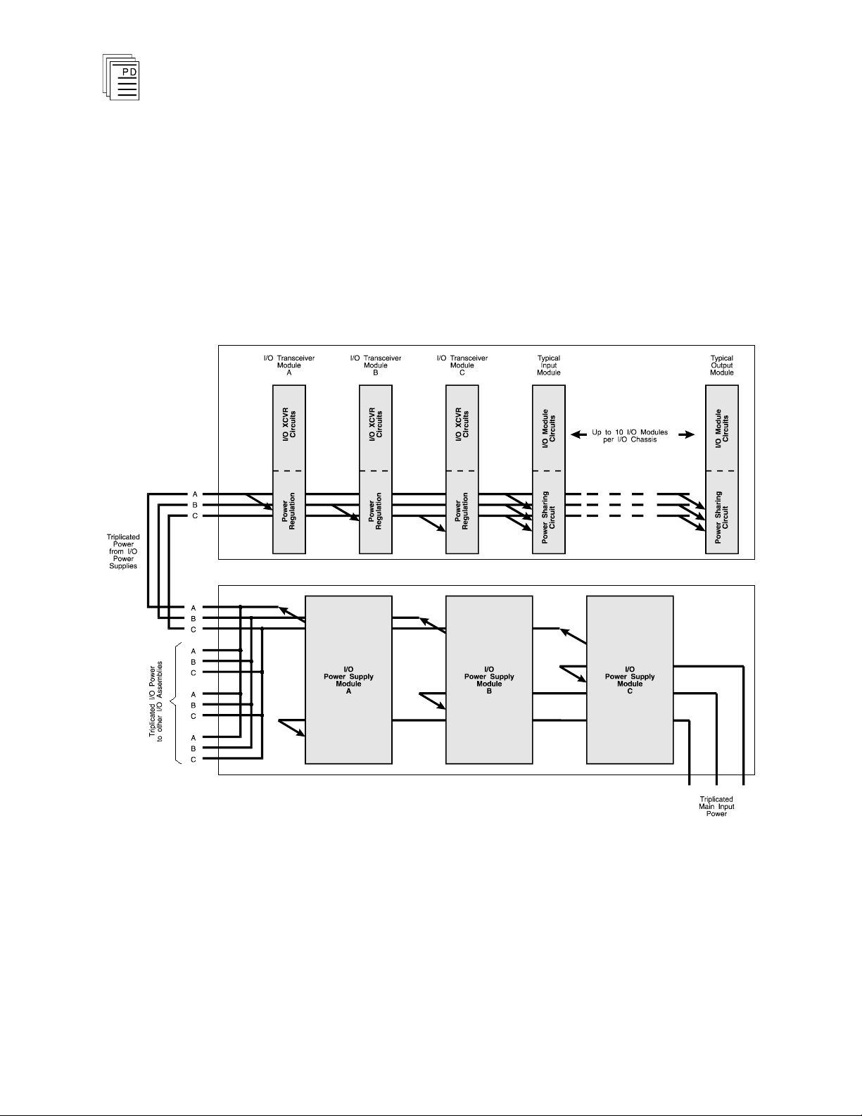
Triplicated Power Distribution
Each of the triple redundant I/O power supply modules within
the I/O power supply assembly provides power for one leg of
the three redundant legs of the I/O Safetybus transceivers,
and provides power to all the I/O modules within its associated
I/O chassis. Each I/O module contains a diode OR power
-
Industrial Control Services
1
Page 2
I/O Power Supply Modules
sharing circuit that receives power from all three I/O power
supply modules.
Should any I/O power supply module fail, only one leg of the
transceiver modules will lose power: the two remaining legs
will maintain proper operation of the Regent. In addition, all
the I/O modules will continue to operate properly by drawing
their current from the two remaining power supplies within
the I/O power supply assembly.
(T3510, 11, and 12)
2
Figure 1. I/O Power Distribution.
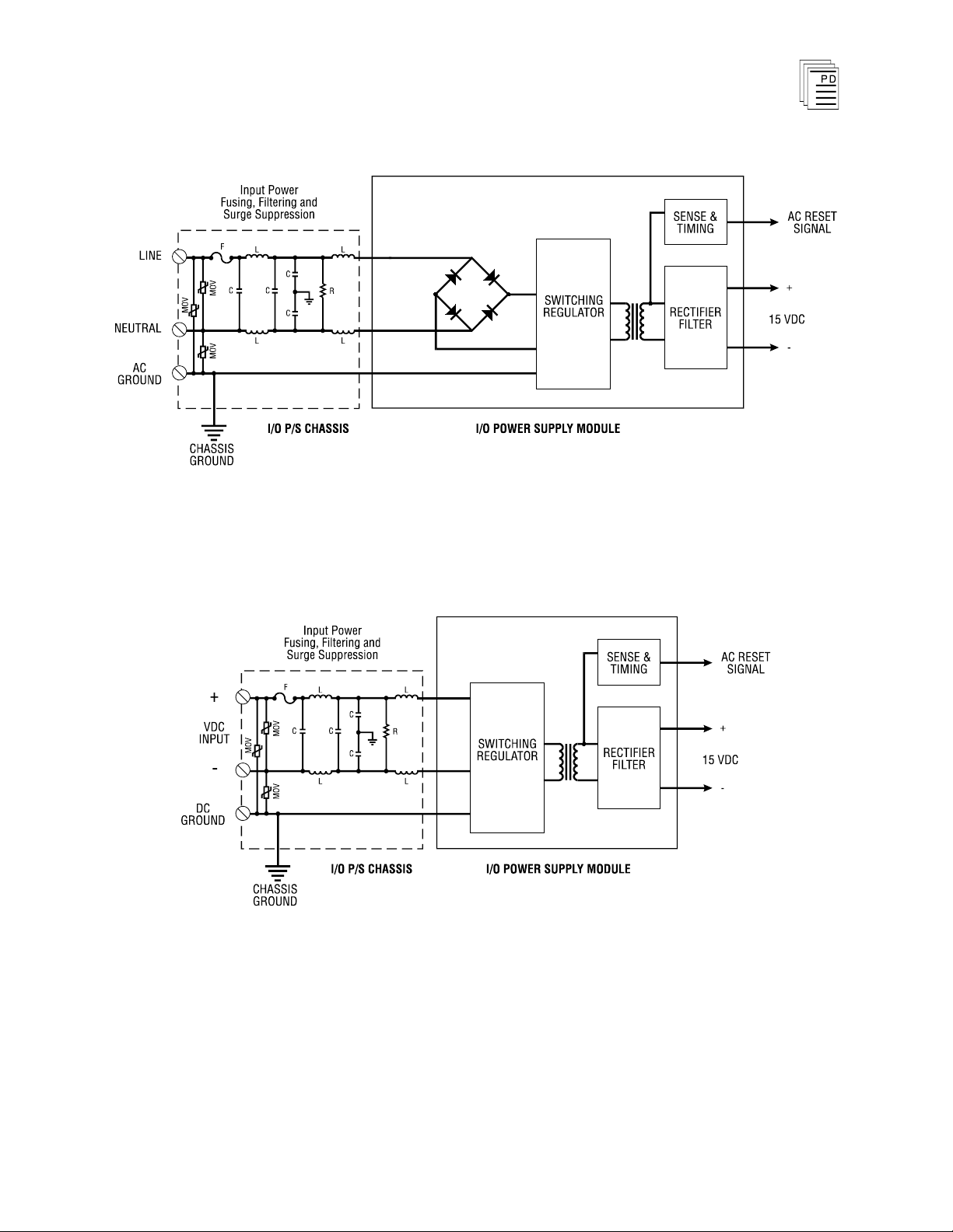
Input Power Regulation
A block diagram of a typical AC I/O power supply module is
shown in Figure 2. A DC I/O power supply module is shown in
Figure 3.
Industrial Control Services
Page 3
I/O Power Supply Modules
(T3510, 11, and 12)
Figure 2. Block Diagram of an AC I/O Power Supply Module.
Figure 3. Block Diagram of
a DC I/O Power Supply Module.
PD-6008
Mar-06
Each primary power input is individually fused and filtered
(with both standard line filters and metal oxide varistors, or
MOVs) at the chassis. The filters are used to attenuate high
frequency common mode and normal mode noise that can be
3
Page 4

I/O Power Supply Modules
present in power distribution systems. The MOVs provide
clamping of high voltage transients.
On board the power supply module the switching regulator
and rectifier filter circuits convert the primary input power to
15 VDC. Sensing and timing circuits monitor for over
voltage, over-current (including current limiting), and power
failure.
An AC reset signal is used in the I/O transceivers for power
system interlocking within the I/O system. Should a power
failure occur (either input power or module fault), the AC
reset signal is activated and the front panel indicator is
turned off.
(T3510, 11, and 12)
-
Front Panel Indicator
Figure 4 shows the physical features of the I/O power supply
modules. The front panel of each module contains
power indicator.
Output Power Indicator
an output
The green OUTPUT POWER indicator is turned on when the
I/O power supply module's DC output is within tolerance. Out
of tolerance conditions, loss of input power or brown-out, and
module failures will cause the OUTPUT POWER indicator to
turn off.
4
Industrial Control Services
Page 5

I/O Power Supply Modules
(T3510, 11, and 12)
Application
PD-6008
Mar-06
5
Figure 4. I/O Power Supply Module.
Input Power Voltages
Before installing I/O power supply modules, always make
certain that their input power voltage matches the voltage of
the I/O power supply chassis. All the power supply modules on
the chassis must also have the same voltage.
Page 6

Input Power Voltage
I/O Power Supply
Chassis
I/O Power Supply
Module
110 VAC
T3500
T3510
220/240 VAC
T3501
T3511
24 VDC
T3502
T3512
I/O Power Supply Modules
Use Table 1 to verify voltage compatibility for your I/O power
supply chassis and I/O power supply modules.
(T3510, 11, and 12)
Table 1. Matching Input Power Voltages.
Power Supply Load Units
P
ower supply unit loading is based on the number of I/O
modules in the chassis and the load imposed by each I/O
module. Load units for each I/O module are shown in that
module’s product description and specification sheet under the
heading “Safetybus Power.” I/O power supply load units are
shown on page 7, as “Available Load Units.”
Calculating the number of load units in your system will help
you determine the number of I/O power supplies your system
will need. For economic power di
stribution, and to avoid
overloading individual power supply units, power supply
loading should be calculated when configuring systems.
Maintenance
Safety C
6
onsiderations
No periodic maintenance or calibration is required for I/O
power supply modules. There are no user replaceable parts
inside these modules.
When an I/O power supply module fails, it can be hot-replaced
without disrupting system operations. Main power wiring and
I/O power cables (connected to the chassis) are not disturbed
during module replacement.
The T3510 (110 VAC) and T3512 (24 VDC) I/O power supply
modules are TÜV certified for Risk Class 5 safety critical
applications. Model T3511 (220 VAC) is excluded as it does
Industrial Control Services
Page 7

I/O Power Supply Modules
Available Load Units
Number of I/O Units:
Load Unit Capacity:
1 2 3 4
52
48
44
40
Voltage Range
T3510
T3511
T3512
85 to 132 VAC
170 to 263 VAC
20 to 30 VDC
Frequency Range
T3510
T3511
T3512
47 to 63 Hz
47 to 63 Hz
—
Maximum Load
250 VA, per module
Heat Dissipation
22 Watts, 75 BTUs/hour
Use with Chassis
T3510
T3511
T3512
T3500
T3501
T3502
Fusing (on chassis)
T3510 (110 VAC)
T3511 (220 VAC)
T3512 (24 VDC)
4A, 250 V, 3AG Slow Blow
2A, 250 V, 3AG Slow Blow
10 A, 250 V, 3AB Slow Blow
Output Voltage
+15 volts
Power Hold-up Time
10 msec, minimum
Operating Temperature
0°
to 60° C
(32° to 140° F)
Storage Temperature
-40°
to 85° C
(-40°
to 185° F)
Operating Humidity
0 to 95% relative humidity,
non-condensing
Vibration
10 to 55 Hz:
±0.15mm
(T3510, 11, and 12)
not meet the DIN VDE 0110 specification for creepage and
clearance required by TÜV.
Specifications
PD-6008
Mar-06
7
Page 8

Shock
Operating:
15 g, ½ sine wave, 11 msec
Electromagnetic
Interference
•
IEC 801 Part 2 - Electrostatic
Discharges
•
IEC 801 Part 3 - Radiated
Electromagnetic Fields
•
IEC 801 Part 4 - Transients
and Bursts
•
IEC 801 Part 5 - Surge
Immunity
•
ANSI/IEEE C37.90 - Surge
Withstand Capability
Level 3: Contact discharge of
6 kV
Level 3: 10 V/M, 27 MHz 500 MHz
Level 4: 2 kV, 2.5 kHz for t =
60 sec
Level 3: 2 kV
2.5 kV damped 1 MHz sine
wave
4 kV bi-directional impulse,
10 nsec rise time, fast
transient
Safety
Certified to DIN V VDE
0801 for Risk Class 5. Also
designed to meet UL 508 and
CSA 22.2, No. 142-M1981
Dimensions
Height:
Width:
Depth:
13.0" (330 mm)
4.12" (105 mm)
10.25" (260 mm)
Weight
7.5 lbs (3.4 kg)
I/O Power Supply Modules
(T3510, 11, and 12)
8
Industrial Control Services
 Loading...