

Page 1

User Manual
ControlLogix Time Syncronization Module - Series B
Catalog Number 1756HP-TIME
Allen-Bradley Motors
Page 2
Important User Information
IMPORTANT
Read this document and the documents listed in the additional resources section about installation, configuration, and
operation of this equipment before you install, configure, operate, or maintain this product. Users are required to
familiarize themselves with installation and wiring instructions in addition to requirements of all applicable codes, laws,
and standards.
Activities including installation, adjustments, putting into service, use, assembly, disassembly, and maintenance are required
t
o be carried out by suitably trained personnel in accordance with applicable code of practice.
If this equipment is used in a manner not specified by the manufacturer, the protection provided by the equipment may be
aired.
imp
In no event will Rockwell Automation, Inc. be responsible or liable for indirect or consequential damages resulting from the
or application of this equipment.
use
The examples and diagrams in this manual are included solely f
or illustrative purposes. Because of the many variables and
requirements associated with any particular installation, Rockwell Automation, Inc. cannot assume responsibility or
liability for actual use based on the examples and diagrams.
No patent liability is assumed by Rockwell Automation, Inc. with respect to use of information, circuits, equipment, or
tware described in this manual.
sof
Reproduction of the contents of this manual, in whole or in part, without written permission of Rockwell Automation,
nc., is prohibited.
I
Throughout this manual, when necessary, we use notes to make you aware of safety considerations.
WARNING: Identifies information about practices or circumstances that can cause an explosion in a hazardous environment,
which may lead to personal injury or death, property damage, or economic loss.
ATTENTION: Identifies information about practices or circumstances that can lead to personal injury or death, property
damage, or economic loss. Attentions help you identify a hazard, avoid a hazard, and recognize the consequence.
Identifies information that is critical for successful application and understanding of the product.
Labels may also be on or inside the equipment to provide specific precautions.
SHOCK HAZARD: Labels may be on or inside the equipment, for example, a drive or motor, to alert people that dangerous
voltage may be present.
BURN HAZARD: Labels may be on or inside the equipment, for example, a drive or motor, to alert people that surfaces may
reach dangerous temperatures.
ARC FLASH HAZARD: Labels may be on or inside the equipment, for example, a motor control center, to alert people to
potential Arc Flash. Arc Flash will cause severe injury or death. Wear proper Personal Protective Equipment (PPE). Follow ALL
Regulatory requirements for safe work practices and for Personal Protective Equipment (PPE).
Allen-Bradley, ControlFLASH, ControlLogix, Logix5000, R SLogix, Studio 5000 Automation Engineering & Design Environment, Studio 5000, Studio 5000 Logix Designer, Rockwell S oftware, and Rockwell Automation
are trademarks of Rockwell Automation, Inc.
Trademarks not belonging to Rockwell Automation are property of their respective companies.
Page 3

Table of Contents
Preface
Installation
Setup
Operation
Studio 5000 Environment . . . . . . . . . . . . . . . . . . . . . . . . . . . . . . . . . . . . . . . . . . 5
1756HP-TIME Module Overview . . . . . . . . . . . . . . . . . . . . . . . . . . . . . . . . . . 5
Additional Resources . . . . . . . . . . . . . . . . . . . . . . . . . . . . . . . . . . . . . . . . . . . . . . .
6
Chapter 1
Hardware . . . . . . . . . . . . . . . . . . . . . . . . . . . . . . . . . . . . . . . . . . . . . . . . . . . . . . . . . 7
GPS Antenna . . . . . . . . . . . . . . . . . . . . . . . . . . . . . . . . . . . . . . . . . . . . . . . . . . . . . . 8
Software. . . . . . . . . . . . . . . . . . . . . . . . . . . . . . . . . . . . . . . . . . . . . . . . . . . . . . . . . . . 8
Chapter 2
BOOTP. . . . . . . . . . . . . . . . . . . . . . . . . . . . . . . . . . . . . . . . . . . . . . . . . . . . . . . . . . . 9
Factory Defaults . . . . . . . . . . . . . . . . . . . . . . . . . . . . . . . . . . . . . . . . . . . . . . . . . . . 9
ControlFLASH Software . . . . . . . . . . . . . . . . . . . . . . . . . . . . . . . . . . . . . . . . . 10
The Logix Designer Application Configuration. . . . . . . . . . . . . . . . . . . . . 10
View the Satellite Status in the Logix Designer Application . . . . . . . . . . 12
Satellite Signal . . . . . . . . . . . . . . . . . . . . . . . . . . . . . . . . . . . . . . . . . . . . . . . 12
Satellite Position . . . . . . . . . . . . . . . . . . . . . . . . . . . . . . . . . . . . . . . . . . . . . 13
1756HP-TIME Module AOP Configuration Parameters. . . . . . . . . . . . 13
Chapter 3
Logix5000 Controller Input Image . . . . . . . . . . . . . . . . . . . . . . . . . . . . . . . . 17
Logix5000 Controller Output Image . . . . . . . . . . . . . . . . . . . . . . . . . . . . . . 20
Web Interface . . . . . . . . . . . . . . . . . . . . . . . . . . . . . . . . . . . . . . . . . . . . . . . . . . . 21
Time Synchronization
Specifications
Chapter 4
1588 Precision Time Protocol (CIP Sync). . . . . . . . . . . . . . . . . . . . . . . . . . 23
1756HP-TIME Module as a PTP Master. . . . . . . . . . . . . . . . . . . . . . . 23
Configure the Ethernet Module/Controller PTP/CIP
Sync Settings. . . . . . . . . . . . . . . . . . . . . . . . . . . . . . . . . . . . . . . . . . . . . . . . .
PTP as a Time Source. . . . . . . . . . . . . . . . . . . . . . . . . . . . . . . . . . . . . . . . . 26
Network Time Protocol (NTP) . . . . . . . . . . . . . . . . . . . . . . . . . . . . . . . . . . .
1756HP-TIME Module as an NTP Server. . . . . . . . . . . . . . . . . . . . . .
1756HP-TIME Module as an NTP Client . . . . . . . . . . . . . . . . . . . . . 28
IRIG-B. . . . . . . . . . . . . . . . . . . . . . . . . . . . . . . . . . . . . . . . . . . . . . . . . . . . . . . . . .
1756HP-TIME Module as an IRIG-B Master
1756HP-TIME Module as an IRIG-B Slave . . . . . . . . . . . . . . . . . . . . 30
CST and UTC Time Conversion . . . . . . . . . . . . . . . . . . . . . . . . . . . . . . . . .
. . . . . . . . . . . . . . . . . . 29
24
26
26
29
30
Appendix A
Technical Specifications . . . . . . . . . . . . . . . . . . . . . . . . . . . . . . . . . . . . . . . . . . 31
Cable Specifications . . . . . . . . . . . . . . . . . . . . . . . . . . . . . . . . . . . . . . . . . . . . . .
GPS Antenna Specifications . . . . . . . . . . . . . . . . . . . . . . . . . . . . . . . . . . . . . . 32
Dimensions. . . . . . . . . . . . . . . . . . . . . . . . . . . . . . . . . . . . . . . . . . . . . . . . . . . . . .
31
33
Allen-Bradley Motors
Rockwell Automation Publication 1756-UM542A-EN-P - September 2014 3
Page 4

Table of Contents
Appendix B
1756HP-TIME Module Status
CST/UTC Conversion Message Blocks
Operating Modes
GPS Antenna Cable Extensions
Status Indicators . . . . . . . . . . . . . . . . . . . . . . . . . . . . . . . . . . . . . . . . . . . . . . . . . 35
Status Messages . . . . . . . . . . . . . . . . . . . . . . . . . . . . . . . . . . . . . . . . . . . . . . . . . .
36
Appendix C
CST to UTC and Gregorian Time Conversion . . . . . . . . . . . . . . . . . . . . . 37
UTC to Gregorian Time Conversion . . . . . . . . . . . . . . . . . . . . . . . . . . . . . . 37
Satellite Information. . . . . . . . . . . . . . . . . . . . . . . . . . . . . . . . . . . . . . . . . . . . . . 38
Appendix D
GPS Source . . . . . . . . . . . . . . . . . . . . . . . . . . . . . . . . . . . . . . . . . . . . . . . . . . . . . . 39
IRIG-B Source . . . . . . . . . . . . . . . . . . . . . . . . . . . . . . . . . . . . . . . . . . . . . . . . . . . 40
PTP Source . . . . . . . . . . . . . . . . . . . . . . . . . . . . . . . . . . . . . . . . . . . . . . . . . . . . . . 40
NTP Source . . . . . . . . . . . . . . . . . . . . . . . . . . . . . . . . . . . . . . . . . . . . . . . . . . . . . 41
Appendix E
Cable Extensions . . . . . . . . . . . . . . . . . . . . . . . . . . . . . . . . . . . . . . . . . . . . . . . . . 43
Determine the Length of the Cable. . . . . . . . . . . . . . . . . . . . . . . . . . . . . 43
Determine the Attenuation Rate of the Cable . . . . . . . . . . . . . . . . . . . 43
Example – Determining Cable Requirements . . . . . . . . . . . . . . . . . . . 44
Cable Extension Kits. . . . . . . . . . . . . . . . . . . . . . . . . . . . . . . . . . . . . . . . . . 44
Lightning Protection Devices. . . . . . . . . . . . . . . . . . . . . . . . . . . . . . . . . . . . . . 45
Glossary
Index
. . . . . . . . . . . . . . . . . . . . . . . . . . . . . . . . . . . . . . . . . . . . . . . . . . . . . . . . . . . . . . . . . 47
. . . . . . . . . . . . . . . . . . . . . . . . . . . . . . . . . . . . . . . . . . . . . . . . . . . . . . . . . . . . . . . . . 49
4 Rockwell Automation Publication 1756-UM542A-EN-P - September 2014
Page 5

Top ic Page
Studio 5000 Environment 5
1756HP-TIME Module Overview 5
Additional Resources 6
Preface
Studio 5000 Environment
The Studio 5000 Automation Engineering & Design Environment™ combines
engineering and design elements into a common environment. The first element
is the Studio 5000 Logix Designer™ application. The Logix Designer application
is the rebranding of RSLogix™ 5000 software and will continue to be the product
to program Logix5000™ controllers for discrete, process, batch, motion, safety,
and drive-based solutions.
The Studio 5000® environment is the foundation for the future of Rockwell
A
utomation® engineering design tools and capabilities. The Studio 5000
environment is the one place for design engineers to develop all of the elements of
their control system.
1756HP-TIME Module Overview
Allen-Bradley Motors
This user manual describes the functionality, installation, configuration, and
operation of the 1756HP-TIME module, series B, firmware revision 3.001.
The 1756HP-TIME module provides accurate time synchronization on different
terfaces by using Global Positioning System (GPS) technology. The
in
1756HP-TIME module can obtain time from various sources, and provide time
synchronization on other devices by acting as a gateway between different time
synchronization methods and standards.
Rockwell Automation Publication 1756-UM542A-EN-P - September 2014 5
Page 6

Preface
Time synchronization is accomplished by using these methods, standards, and
protocols:
• The
ControlLogix® backplane for Coordinated System Time (CST) and
Coordinated Universal Time (UTC) conversion.
• Inter-range Instrumentation Group, code B (IRIG-B) standards.
• Precision Time Protocol (PTP) on Ethernet and the ControlLogix
backplane.
• Network Time Protocol (NTP) on Ethernet.
The 1756HP-TIME module provides GPS position in the form of latitude,
gitude, and altitude (LLA).
lon
The 1756HP-TIME module provides course and route information in the form
round speed (knots) with heading in the form of degrees from true north.
of g
Additional Resources
These documents contain additional information concerning related products
from Rockwell Automation.
Resource Description
Integrated Architecture and CIP Sync Configuration
Application Technique, publication IA-AT003
ControlLogix System User Manual, publication 1756-UM001 Describes the necessary tasks to install, configure,
EtherNet/IP Network Configuration User Manual,
publication
ControlFLASH® Firmware Upgrade Software User Manua l,
publication 1756-UM105
Industrial Automation Wiring and Grounding Guidelines,
publication 1770-4.1
Product Certifications website,
ENET-UM001
http://www.ab.com Provides declarations of conformity, certificates, and
This document explains CIP sync technology and how
you can synchronize clocks within the Rockwell
Automation Integrated Architecture.
program, and operate a ControlLogix system.
Provides Bootstrap Protocol/ Dynamic Host
Configuration Protocol (BOOTP/DHCP) information for
setting the IP address of the module.
Describes the necessary tasks to install, and use the
ControlFLASH software to update the module firmware.
Provides general guidelines for installing a Rockwell
Automation industrial system.
other certification details.
You can view or download publications at
http:/www.rockwellautomation.com/literature/. To order paper copies of
technical documentation, contact your local Allen-Bradley distributor or
R
ockwell Automation sales representative.
6 Rockwell Automation Publication 1756-UM542A-EN-P - September 2014
Page 7
Installation
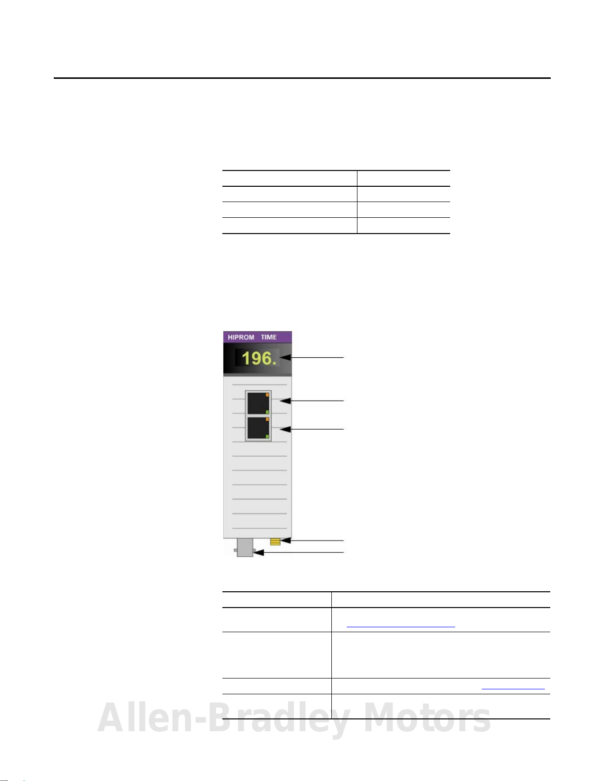
Status Indicators and Messages
Ethernet Connection 1
Ethernet Connection 2
GPS Subminiture Version A (SMA) Connector
IRIG-B Coaxial Connector
Top ic Page
Hardware 7
GPS Antenna 8
Software 8
Chapter 1
Hardware
The 1756HP-TIME module operates within the ControlLogix platform. All
power required for the operation of the module is supplied by the ControlLogix
backplane.
Figure 1 - 1756HP-TIME Module, Front View
Table 1 - 1756HP-TIME Module Hardware Descriptions
Hardware Description
Status indicators and messages Provides status and operational information for the 1756HP-TIME module.
Ethernet connector 1 and
Ethernet connector 2
(uses Rockwell Automation®
dual-port switch technology)
GPS SMA connector Connect the GPS b ullet antenna to this connector. See GPS Antenna on page 8.
IRIG-B coaxial connec tor Connect the IRIG-B network cable to this connector. The 1756HP-TIME module
See 1756HP-TIME Module Status on page 35.
PTP and NTP time synchronization uses the Ethernet connections.
Note: This connection is not a bridge to the backplane and cannot be used to
view m
odules on the backplane.
can be configured as a master clock or a slave clock on the IRIG-B network.
Allen-Bradley Motors
Rockwell Automation Publication 1756-UM542A-EN-P - September 2014 7
Page 8
Chapter 1 Installation
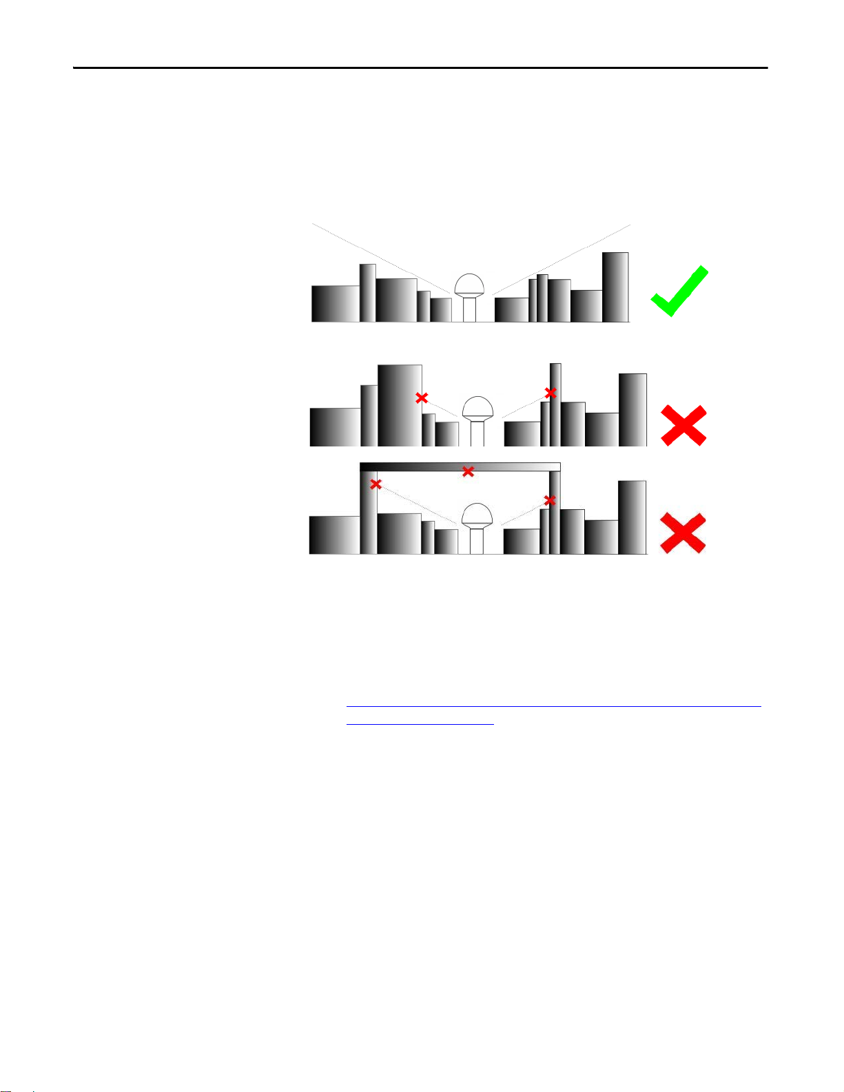
GPS Antenna
Install the GPS antenna with a clear view of the sky (do not install the antenna
where objects can obstruct the view of the antenna to the sky). If an antenna is
installed with a limited view of the sky, the GPS receiver can have a low satellite
lock count, or be unable to obtain a lock. A limited view of the sky can cause
inaccurate time synchronization.
Figure 2 - GPS Antenna Installation with Clear View of the Sky
Figure 3 - GPS Antenna Installation with Obstructed View of the Sky
Software
Use this software to configure and operate the 1756HP-TIME module:
• The Studio 5000 Logix Designer application
• The Add-on Profile (AOP) for the 1756HP-TIME module, available for
download at this link:
http://www.hiprom.com/Pages/Products/1756_CLX/1756HP-TIME/
web/1756HP-TIME.htm
8 Rockwell Automation Publication 1756-UM542A-EN-P - September 2014
Page 9

Setup
Top ic Page
BOOTP 9
Fac tory Defaul ts 9
ControlFLASH Software 10
The Logix Designer Application Configuration 10
View the Satellite Status in the Logix Designer Application 12
1756HP-TIME Module AOP Configuration Parameters 13
Chapter 2
BOOTP
Factory Defaults
Use BOOTP to set the initial IP address for the 1756HP-TIME module. The
module comes from the factory with BOOTP enabled.
The BOOTP/DHCP server is a standalone server that you can use to set an IP
s.
addres
Access the BOOTP/DHCP server from one of these locations:
rograms > Rockwell Software > BOOTP-DHCP Server
• P
• Tools directory on the Studio 5000 environment installation CD
If you have not installed the BOOTP/DHCP server, you can download and
ll it from
insta
To set the IP address of the module with a BOOTP/DHCP server, follow the
ps found in EtherNet/IP Network Configuration User Manual, publication
ste
ENET-UM001.
If the module fails or becomes inoperable, the module reboots with
factory-loaded boot software. The display informs you of the error and suggests a
method to fix the error. If there is a firmware error, use the ControlFLASH
software to restore the module to a working condition.
http://www.ab.com/linked/networks/ethernet/bootp.html.
Allen-Bradley Motors
Rockwell Automation Publication 1756-UM542A-EN-P - September 2014 9
Page 10
Chapter 2 Setup
IMPORTANT
IMPORTANT
ControlFLASH Software
The Logix Designer Application Configuration
Use the ControlFLASH software to upgrade the software to a newer version.
For more information on the ControlFLASH software and how to use it, see
C
ontrolFLASH Firmware Upgrade Software User Manual, publication
UM105.
The latest firmware can be found at this link:
Products/1756_CLX/1756HP-TIME/web/1756HP-TIME.htm.
Before you can program the 1756HP-TIME module, the AOP for the module
must be installed. You also need admin rights for the module to view and
configure the AOP.
The installer for the AOP can be found at this link:
http://www.hiprom.com/Pages/Products/1756_CLX/1756HP-TIME/web/
1756HP-TIME.htm.
Each 1756HP-TIME module is programmed to work with a single Logix5000
controller.
http://www.hiprom.com/Pages/
1756-
There is no direct communication between the 1756HP-TIME module Ethernet
ports and a Logix5000 controller. If the 1756HP-TIME module resides in a
remote Logix rack, it needs to communicate through an EN2T(R) module in the
same rack.
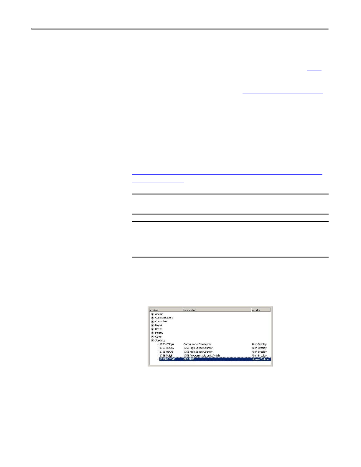
Follow these steps to configure the 1756HP-TIME module in the Logix
Designer application.
1. Doub
le-click the 1756HP-TIME module in the I/O tree in the Logix
Designer application.
The New Module dialog box appears.
10 Rockwell Automation Publication 1756-UM542A-EN-P - September 2014
Page 11
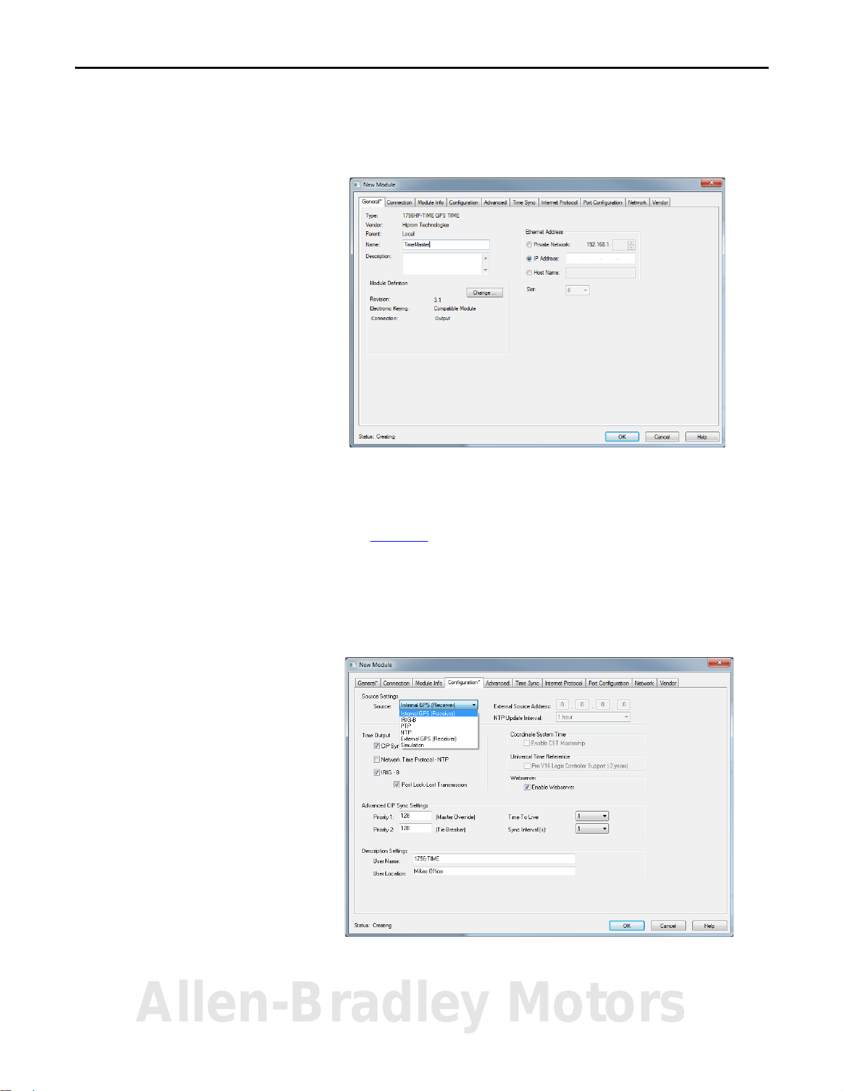
2. Enter a name for the module.
3. Enter a brief description for the module.
4. Enter the IP address for the module.
Setup Chapter 2
5. Click the Configuration tab.
6. From the Source Settings pull-down menu, choose the time source that
you want to use.
See Chapter 4
7. Select the Time Output format.
8. Enter the Advanced CIP Sync Settings.
9. Enter the Description Settings.
10. Click OK.
for more information on the source types.
The time properties of the 1756HP-TIME module are now configured.
Allen-Bradley Motors
Rockwell Automation Publication 1756-UM542A-EN-P - September 2014 11
Page 12
Chapter 2 Setup
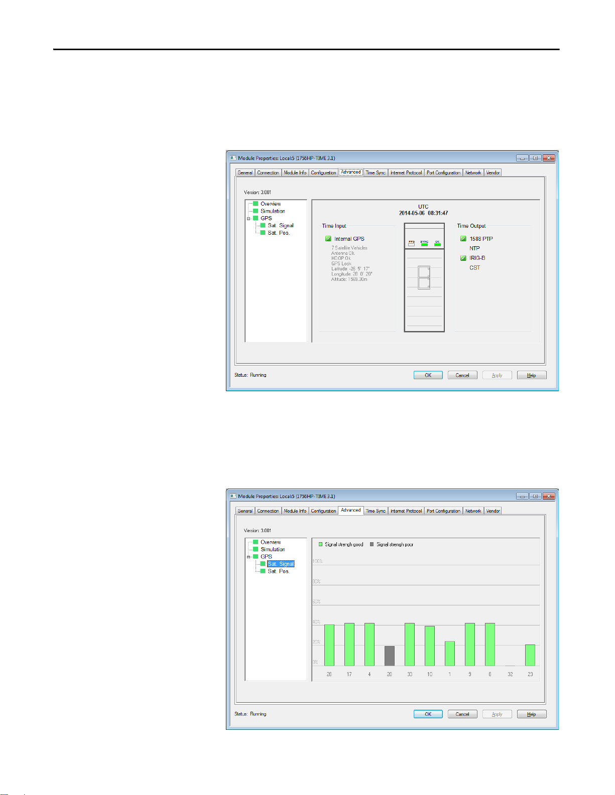
View the Satellite Status in the Logix Designer Application
Click the Advanced tab to view the source of the time (Time Input), and see if
the time source is valid and available (green) or invalid (red). You can also view
the output type (Time Output), the UTC time of the 1756HP-TIME module,
and the GPS coordinates of the satellite (when a connection is locked).
Figure 4 - 1756HP-TIME Module Properties Dialogue Box, Advanced Tab
Satellite Signal
Click Sat. Signal to view the signal strength of the satellites.
Figure 5 - 1756HP-TIME Module Properties Dialogue Box, Sat. Signal Node
12 Rockwell Automation Publication 1756-UM542A-EN-P - September 2014
Page 13
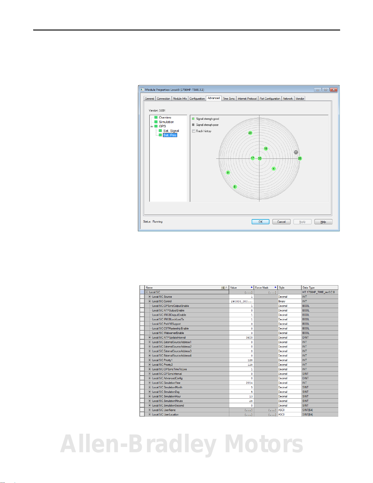
Satellite Position
Click Sat. Pos. to view the position of the satellites in the sky.
Figure 6 - 1756HP-TIME Module Properties Dialogue Box, Sat. Pos. Node
Setup Chapter 2
1756HP-TIME Module AOP Configuration Parameters
This section describes the AOP configuration parameters for the 1756HP-TIME
module. This section is for information purposes. The AOP is used to configure
all the relevant module parameters.
Allen-Bradley Motors
Rockwell Automation Publication 1756-UM542A-EN-P - September 2014 13
Page 14

Chapter 2 Setup
Table 2 - AOP Configuration Parameters
Parameter Description Value
Source Indicates the time source that is used for the module. 1 = GPS
2 = IRIG-B
3 = PTP
4 = NTP
5 = External GPS (future)
6 = Simulation
CIPSyncOutputEnable When this bit is set, the module enables 1588 PTP (CIP sync) output. 0 = 1588 PTP (CIP sync) output is disabled
1 = 1588 PTP (CIP sync) output is enabled
NTPOutputEnable When this bit is set, the module enables NTP on Ethernet. 0 = NTP v3 RF(1305) output is disabled
1 = NTP v3 RF(1305) output is enabled
IRIGBOutputEnable When this bit is set, the module enables IRIG-B on the coaxial interface. 0 = IRIG-B-122 output is disabled
1 = IRIG-B-122 output is enabled
IRIGBLockLostTX When this bit is set, the module keeps sending an IRIG-B signal aft
PreV16Support If you are using RSLogix 5000 software, version 16.00.00 and later, or the Studio 5000
CSTMastershipEnable Indicates if the module is the CST master clock on the local rack (if no other CST master
WebserverEnable Allows you to access the web server from a web browser pointed to the IP address of the
NTPUpdateInterval The time (in seconds) when the module requests an update of the time from the NTP
ExternalSo urceAddress The external source address is used for one of two sources depending on how the
Priority1 This is the override for the Best Master Clock Algorithm (BMCA). The default is 128.
Priority2 This is used to break a tie between two modules with the same priority 1 value. The default is 128.
CIPSyncTimeToLive Limits the lifespan of data in a network. It
CIPSyncInterval The time interval when the module sends out a PTP sync packet. Allowed values:
AdvancedConfig These are various bits used to set c
time source.
If this bit is clear, the module stops sending a valid IRIG-B signal when it has lost lock
with the time source, as long as it has had lock at least once previously.
environment, version 21.00.00 and later, the UTC time base is different than earlier
versions of RSLogix 5000 software.
The setting syncs the time between Logix5000 controllers that use any version of
RSLogix 5000 software or the Studio 5000 environment.
clocks are currently active).
module.
server.
guration is set:
confi
• If the time source is set to NTP, this is the IP address of the source that is used.
• If the source is set to External GPS, this is the IP address of the GPS receiver.
indefinitely.
prevents the IP packet from circulating
ertain options in the module. Bit:
er it has lost lo ck to th e
0 = Module stops sending IRIG-B when lock is lost
1 = Module continues sending IRIG-B, even when a lock is
lost
0 = For all versions of RSLogix 5000 software or the Studio
5000 environment
1 = For RSLogix 5000 software, version 16.00.00 and earlier.
0 = Module does not attempt to be the CST master clock
1 = Module does attempt to be the CST master clock
0 = Module does not allow access to the web server
1 = Module allows access to the web server
Example:
5 = 5 seconds
30 = 30 seconds
300 = 5 minutes
3600 = 1 hour
86400 = 1 day
604800 = 1 week
In this example, the module uses external IP address:
192.168.1.100
Byte 0 = 192
Byte 1 = 168
Byte 2 = 1
Byte 3 = 100
Values lower than 128 indicate preference on the network.
Values lower than 128 indicate preference on the network.
Example:
1 = the packet circulates once
1/2 = 500 ms
1 = 1 second
2 = 2 seconds
0 =Simulation Mode
1…31 = Reserved
14 Rockwell Automation Publication 1756-UM542A-EN-P - September 2014
Page 15

Table 2 - AOP Configuration Parameters (Continued)
Parameter Description Value
SimulationYear When the module is in simulation mode, use this to set the initial year to be used by the
SimulationMonth When the module is in simulation mode, use this to set the initial month to be used by
SimulationDay When the module is in simulation mode, use this to set the initial day to be used by the
SimulationHour When the module is in simulation mode, use this to set the initial hour to be used by the
SimulationMinute When the module is in simulation mode, use this to set the initial minute to be used by
SimulationSecond When the module is in simulation mode, use this to set the initial second to be used by
UserName Use this parameter to identify the time module, visible in CIP sync synchronization. Example:
UserLocation Use this parameter to provide extra information to identify the location of the module. Example:
module.
the module.
.
module
module.
the module.
the module
.
Example:
29 April 2014
Year = 2014
Example:
29 April 2014
Month = 4
Example:
29 April 2014
Day = 29
Example:
11:14:23 AM
Hour =11
Example:
11:14:23 AM
Minute =14
Example:
11:14:23 AM
Second =23
1756HP-TIME
Basement
Setup Chapter 2
Allen-Bradley Motors
Rockwell Automation Publication 1756-UM542A-EN-P - September 2014 15
Page 16

Chapter 2 Setup
Notes:
16 Rockwell Automation Publication 1756-UM542A-EN-P - September 2014
Page 17

Operation
Top ic Page
Logix5000 Controller Input Image 17
Logix5000 Controller Output Image 20
Web Int erf ace 21
Chapter 3
Logix5000 Controller Input Image
Each 1756HP-TIME module consumes one connection from the Logix5000
controller. This section provides descriptions for the Logix5000 controller input
image parameters.
Allen-Bradley Motors
Rockwell Automation Publication 1756-UM542A-EN-P - September 2014 17
Page 18

Chapter 3 Operation
Table 3 - Logix5000 Controller Input Image Parameters
Parameter Description Value
CommStatus Reserved. –
Source Indicates the current time source. 1 = GPS
2 = IRIG-B
3 = PTP
4 = NTP
5 = External GPS (future)
6 = Simulation
ModuleStatus Reserved. –
WebserverEnable Allows you to access the web server from a web browser pointed to
Time.TimeValid Indicates if a valid time is being received from the time source. 0 = Time being received from source is invalid
Time.CIPSyncOutputEnable Indicates if the 1588 Output PTP is enabled in the configuration. 0 = 1588 PTP (CIP Sync) output is disabled
Time.NTPOutputEnable Indicates if the NTP Output is enabled in the configuration. 0 = NTP v3 RF(1305) output is disabled
Time.IRIGBOutputEnable Indicates if the IRIG-B Output is enabled in the configuration. 0 = IRIG-B-122 output is disabled
Time.CSTMasterEnabled Indicates if the module is enabled to be the CST master clock. 0 = Module does not attempt to be the CST master clock
Time.CSTMastership Indicates if the module is the CST master clock on the local rack. 0 = Module is not the CST master clock
Time.CSTDuplicateDetect Indicates if the module is attempting to be the CST master clock.
Time.SimulationModeActive Indicates if the module is operating in simulation mode. 0 = Simulation mode is inactive
Time.Year Displays the current year received from the time source. Example:
Time.Month Displays the current month received from the time source. Example:
Time.Day Displays the current day received from the time source. Example:
Time.Hour Displays the current hour received from the time source. Example:
Time.Minute Displays the current minute received from the time source. Example:
IP address of the module.
the
If there is another CST master clock on the local rack, the module sets
this bit and stops attempting to be the CST master clock.
0 = Module does not allow access to the web server
1 = Module allows access to the web server
1 = Time being received from source is valid
1 = 1588 PTP (CIP Sync) output is enabled
1 = NTP v3 RF(1305) output is enabled
1 = IRIG-B-122 output is enabled
1 = Module does attempt to be the CST master clock
1 = Module is the CST master clock
0 = There is no other CST master clock on the local rack
1 = There is another CST master clock on the local rack
1 = Simulation mode is active
27/04/2010
13:45:22 - 234567 μs
Year = 2010
27/04/2010
13:45:22 - 234567 μs
Month = 4
27/04/2010
13:45:22 - 234567 μs
Day = 27
27/04/2010
13:45:22 - 234567 μs
Hour = 13
27/04/2010
13:45:22 - 234567 μs
Minute = 45
18 Rockwell Automation Publication 1756-UM542A-EN-P - September 2014
Page 19

Table 3 - Logix5000 Controller Input Image Parameters (continued)
Parameter Description Value
Time.Second Displays the current second received from the time source. Example:
27/04/2010
13:45:22 - 234567 μs
Second = 22
Time.Microsecond Displays the current microsecond received from the time source. Example:
27/04/2010
13:45:22 - 234567 μs
Microsecond = 234567
Time.UTC This is the current UTC in microseconds since the time base. The time
Time.CST Displays the current CST of the local rack (depending on the CST
Time.CSTOffset Displays the difference between the UTC and CST in microseconds.
GPS.GPSLock Indicates if the GPS receiver has lock (if GPS is the time source). 0 = GPS receiver does not have lock
GPS.AntennaOK Indicates if the GPS antenna is connected and is operational (if GPS is
GPS.HDOPOk Horizontal Dilution of Precision (HDOP) occurs when there are
GPS.PPS The pulse per second toggles at the exact moment the second
GPS.FaultCode Reserved. –
GPS.Mode Reserved. –
GPS.SVCount Indicates the number of satellites that the GPS receiver is locked on. This is a number between 0…12
GPS.Latitude Displays the current position latitude in degrees. Example:
GPS.Longitude Displays the current position longitude in degrees. Example:
GPS.Altitude Displays the current positio
gin is based on all versions of RSLogix 5000 software or the Studio
ori
5000 environment. See the example code for how this is used to time
stamp events in sequence-of-events (SOE) modules in RSLogix 5000
software versions earlier than 18.00.00.
master clock) in microseconds.
Use this to set the wall clock in the Logix5000 controller in RSLogix
5000 software versions earlier than 18.00.00. Click this link to see
example code:
http://www.hiprom.com/Pages/Products/1756_CLX/1756HP-TIME/
web/1756HP-TIME.htm.
source).
the time
sufficient satellites in lock, but two or more satellites occupy similar
positions in the sky (therefore decreasing the number of effective
satellites).
changes and the microseconds are zero.
Note: because the actual RPI is 50 ms, the accuracy is lost in the input
image.
n altitude in meters. Example:
Example:
02 April 2014
14:12:41
UTC = 87277992127872
Example:
CST master clock running for 1 hour
CST = 3600000000
Example:
CSTOffset = UTC - CST
UTC = 87277992127872
CST = 3600000000
CSTOffset = 87274392127872
1 = GPS receiver has locked onto sufficient satellites
0 = The antenna is either not present or is faulty
1 = The antenna is connected correctly and is operational
0 = HDOP is currently active
1 = HDOP is not active
0 = It has been more than 100 ms since the rollover pulse of the
last second
1 = It has been less than 100 ms since the rollover pulse of the
last second
S26°05'17.0"
E28°00'21.3"
Elev: 1577m
Latitude = -26.088087
S26°05'17.0"
E28°00'21.3"
Elev: 1577m
Longitude = 28.00586
S26°05'17.0"
E28°00'21.3"
Elev: 1577m
Elevation = 1577
Operation Chapter 3
Allen-Bradley Motors
Rockwell Automation Publication 1756-UM542A-EN-P - September 2014 19
Page 20

Chapter 3 Operation
Table 3 - Logix5000 Controller Input Image Parameters (continued)
Parameter Description Value
GPS.GroundSpeed Displays the ground speed, in meters per second. Example: 10.2m/s
GPS.DegreeFromTrueNorth Displays the degrees from true north. Example:
279.12°
GPS.MagneticVariationFromTrueNorth Displays the magnetic variation from true north. Example:
-18.1°
GPS.RelativePositionX Reserved. –
GPS.RelativePositionY Reserved. –
GPS.RelativePositionZ Reserved. –
Logix5000 Controller Output Image
This section provides descriptions for the Logix5000 controller output image
parameters.
Table 4 - Logix5000 Controller Output Image Parameters
Parameter Description Value
IRIGYear When the module has an IRIG-B time source, the year is not passed
over IRIG-B. Enter the current year here in the output image.
UTC_Offset The UTC_Offset is used only when the time source is IRIG-B, and PTP
output is enabled.
IRIG-B provides the UTC time, while PTP requires International
Atomic Time (TAI). The difference between the two is the UTC offset.
ReferencePositionX Reserved. –
ReferencePositionY Reserved. –
ReferencePositionZ Reserved. –
Example:
30 April 2014
IRIGYear = 2014
Example:
30 April 2014
UTC_Offset = 35
Be sure to verify the current UTC offset. The UTC offset changes
ap
proximately every 18 months.
20 Rockwell Automation Publication 1756-UM542A-EN-P - September 2014
Page 21

Operation Chapter 3
Web Interface
The web interface is disabled by default. Follow these steps to enable the web
interface.
n the configuration tab, check Enable Webserver.
1. O
2. Click OK.
You can access the web interface from any computer that has a web browser.
Enter ht
bar of your web browser.
For example, enter the IP address as shown here.
The web interface provides diagnostics and statistics for the 1756HP-TIME
mo
tp:// and the IP address of the 1756HP-TIME module into the address
dule.
Allen-Bradley Motors
Rockwell Automation Publication 1756-UM542A-EN-P - September 2014 21
Page 22

Chapter 3 Operation
Notes:
22 Rockwell Automation Publication 1756-UM542A-EN-P - September 2014
Page 23

Time Synchronization
IMPORTANT
IMPORTANT
Top ic Page
1588 Precision Time Protocol (CIP Sync) 23
Network Time Protocol (NTP) 26
IRIG-B 29
CST and UTC Time Conversion 30
Chapter 4
1588 Precision Time Protocol (CIP Sync)
The 1756HP-TIME module supports 1588 PTP which enables high-precision
time synchronization over an Ethernet network or the chassis backplane. When
PTP is selected, both Ethernet and backplane synchronization is enabled. In the
case of PTP output, the module outputs time over both the backplane and
Ethernet (if connected). In the case of PTP as a time source, the module searches
for the best clock on both media.
See the Integrated Architecture and CIP Sync Configuration Application
Te
c hn i qu e, pu b l ic at io n
IA-AT003, for details on how to use this object.
RSLogix 5000 software, version 18.00.00 and later, or the Studio 5000
environment, version 21.00.00 and later, supports 1588 PTP.
RSLogix 5000 software, version 17.00.00 and earlier, does not support
1588 PTP.
The 1756HP-TIME module supports PTP software version 2.
1756HP-TIME Module as a PTP Master
When locked onto sufficient satellites, the 1756HP-TIME module can
synchronize devices to within 100 ns (by using 1588 PTP) when connected
directly to the device that is being synchronized. If these devices are connected via
a switch that does not support 1588 PTP (transparent and boundary clock
modes), the time synchronization degrades because there are more random delays
that can affect the mean-delay time calculation used for time synchronization.
Therefore, the more switches and interfaces between the 1756HP-TIME module
and the devices being synchronized, the bigger the spread of random time delays
that can result in lower time sync accuracy.
Allen-Bradley Motors
Rockwell Automation Publication 1756-UM542A-EN-P - September 2014 23
Page 24

Chapter 4 Time Synchronization
IMPORTANT
IMPORTANT
IMPORTANT
If you enable CIP Sync on a 1756-EN2T/1756-EN2TR module, the module
looks for other 1588 PTP devices and syncs to the device that has the highestquality clock.
1588 PTP uses a multicast address; therefore, set the switches to allow
multicast, or have IGMP enabled.
There is no direct communication between the 1756HP-TIME module Ethernet
ports and a Logix5000 controller. If the 1756HP-TIME module resides in a
remote Logix rack, it needs to communicate through an EN2T(R) module in the
same rack.
The 1756-EN2T/1756-EN2TR modules are boundary clocks that can be a slave
clock on one interface, and a master clock on another interface. The modules can
act as a transparent gateway when a Logix5000 controller uses the time
Grandmaster (the 1756HP-TIME module) on the network. The 1756-EN2T/
1756-EN2TR module must have CIP Sync and Motion enabled. See
Configure
the Ethernet Module/Controller PTP/CIP Sync Settings on page 24.
Most devices supporting 1588 PTP defaults to PTP Enabled: FALSE.
PTP must be enabled on the devices before time synchronization can begin.
Configure the Ethernet Module/Controller PTP/CIP Sync Settings
Follow these steps to configure the PTP/CIP Sync settings of the 1756-EN2T/
1756-EN2TR module and controller.
en the AOP for the Ethernet module.
1. Op
2. From the General tab, under Module Definition, click Change.
24 Rockwell Automation Publication 1756-UM542A-EN-P - September 2014
Page 25

Time Synchronization Chapter 4
3. From the Time Sync Connection pull-down menu, choose Time Sync and
Motion.
4. Click OK.
The 1756-EN2T/1756-EN2TR module is now configured for PTP
synchronization.
5. To enable synchronization on the controller, open the Controller AOP.
6. On the Date/Time tab, check the Enable Time Synchronization box.
The Logix5000 controller looks for the highest-quality clock on the
plane.
back
7. Click OK.
The settings of the Ethernet module and controller module are now configured
or time sync and motion.
f
Allen-Bradley Motors
Rockwell Automation Publication 1756-UM542A-EN-P - September 2014 25
Page 26

Chapter 4 Time Synchronization
IMPORTANT
IMPORTANT
IMPORTANT
IMPORTANT
PTP as a Time Source
The 1756HP-TIME module can be set to be a PTP slave. The module
synchronizes to the best PTP clock on either the backplane or the Ethernet
network, using the best master clock algorithm (BMC).
The TIME module cannot act as a boundary clock. If PTP is selected as the input
time source, then PTP output is disabled.
Using PTP as the time source enables NTP and IRIG-B as the output modes.
herefore, the accuracy is limited to the accuracy of the respective output modes.
T
The accuracy of the PTP time is dependent on the quality and reliability of the
Ethernet network. The PTP algorithm allows for network delays, but needs a
constant delay to synchronize accurately. PTP switches prioritize PTP messages
to keep the delay constant, and are preferred for PTP networks.
Network Time Protocol (NTP)
This section describes how to configure the 1756HP-TIME module as an NTP
server or an NTP client.
1756HP-TIME Module as an NTP Server
The 1756HP-TIME module supports NTP, which provides time
synchronization over an Ethernet network. NTP clients can be synchronized to
approximately 1ms of the NTP client, depending on the network configuration
and reliability.
NTP is typically used when synchronizing personal computers or domain
con
trollers. You can use the Hiprom Software Network Time Protocol
(HSNTP) application to set the Windows time service on a personal computer
to synchronize to the 1756HP-TIME module. Download the HSNTP
application from
www.hiprom.com.
The 1756HP-TIME module supports NTP version 3, RFC1305.
When a computer is on a domain, it tries to synchronize to the domain
controller. Therefore, you can set up the domain controller to synchronize to
the 1756HP-TIME module.
26 Rockwell Automation Publication 1756-UM542A-EN-P - September 2014
Page 27

Time Synchronization Chapter 4
Configure Windows NTP Settings
Follow these steps to configure the Windows time service to synchronize to the
1756HP-TIME module. Note that the time module and computer need to be on
the same Ethernet network to use NTP.
en the HSNTP application.
1. Op
nter the IP address of the NTP source (the 1756HP-TIME module).
2. E
3. Click Set to update the IP address.
4. From the Update Interval pull-down menu, choose an update interval
time.
5. Click Set to update the update interval time.
6. Click Stop to stop the time service and load the new settings.
7. Click Start to start the time service.
8. Click NTP Source Sync to synchronize the time with the NTP server.
The Windows time service is now configured to synchronize to the
1756H
defaults’.
P-TIME module. To reset the defaults, click Set next to ‘Resort to
Allen-Bradley Motors
Rockwell Automation Publication 1756-UM542A-EN-P - September 2014 27
Page 28

Chapter 4 Time Synchronization
TIP
TIP
1756HP-TIME Module as an NTP Client
You can configure the 1756HP-TIME module to connect to an external NTP
source, and then output the time as PTP or IRIG-B time.
You can also use the SNTP protocol for the source.
Follow these steps to configure the 1756HP-TIME module to an NTP source.
en the Time module AOP in RSLogix 5000 software.
1. Op
2. Click the Configuration tab.
3. From the Source Settings pull-down menu, choose NTP as the source.
The External Source Address and NTP Update Interval options become
available.
4. In the External Source Address field, enter the IP address of the NTP
source.
5. From the NTP Update Interval pull-down menu, choose the update
interval for the 1756HP-TIME module to adjust its internal clock to the
NTP source.
The update interval can range from 5 seconds to 1 week.
The frequency of the update interval affects the accuracy of the time from the
1756HP-TIME module. If the time is not adjusted by the NTP source, the time
can drift by up to 10 μs/s depending on external factors, such as temperature
and humidity.
6. Cl
ick OK.
The 1756HP-TIME module is now configured to an NTP source.
28 Rockwell Automation Publication 1756-UM542A-EN-P - September 2014
Page 29

Time Synchronization Chapter 4
IMPORTANT
IMPORTANT
IMPORTANT
Time Adjustments
To keep the time of the 1756HP-TIME module as smooth as possible, the time is
adjusted in small increments (ramp) until it is equal to the NTP source. If the
time of the 1756HP-TIME module drifts more than 1 second off of the source
time, the 1756HP-TIME module jumps to the time given by the NTP source.
The accuracy of the NTP time depends on the quality and reliability of the
Ethernet network. If the update time is set too high, the clock can drift and
jump. Rockwell Automation recommends a value of 30 seconds or less for
optimal accuracy.
Loss of Communication
If the 1756HP-TIME module loses its connection to the NTP source (if the
source does not reply after the update interval time has expired) then the PPS and
SYNC indicators illuminate red, the TimeValid bit is set to FALSE, and the
1756HP-TIME module runs on its internal oscillator until the NTP source
becomes available again. The 1756HP-TIME module tries to reconnect to the
NTP source every 10 seconds after a loss of communication.
IRIG-B
NTP time as a source is accurate to 10 ms; therefore, the synchronization
accuracy of the output 1588 PTP is limited to 10 ms.
The 1756HP-TIME module can be used as an IRIG-B master clock (outputs the
IRIG-B signal) or an IRIG-B slave clock (receives the IRIG-B signal from
another master clock). The time is transmitted over a coaxial cable, which plugs
into the BNC connector at the bottom of the 1756HP-TIME module.
The 1756HP-TIME module currently supports the IRIG-B-122 format.
1756HP-TIME Module as an IRIG-B Master
When the 1756HP-TIME module is an IRIG-B master clock, it sends the
current time over the IRIG-B network and synchronizes slave clocks to
approximately 1ms.
Note that the 1756HP-TIME module does not send the current year over the
-B network.
IRIG
Allen-Bradley Motors
Rockwell Automation Publication 1756-UM542A-EN-P - September 2014 29
Page 30

Chapter 4 Time Synchronization
IMPORTANT
IMPORTANT
IMPORTANT
IMPORTANT
1756HP-TIME Module as an IRIG-B Slave
The 1756HP-TIME module can synchronize to an external IRIG-B source using
coaxial cable. The source needs to output IRIG-B 122 format time.
The current year for the IRIG-B format is not supported by the 1756HP-TIME
module. Therefore, you need to supply the current year in the output image of
the module in RSLogix 5000 software. A simple rung of ladder logic increases
the year without your intervention.
You can also use the 1756HP-TIME module to output 1588 PTP and NTP
hile receiving time from an IRIG-B source.
w
If using PTP as an output, you must also supply the UTC offset in the output
image. The current value is 35, but this changes periodically. To keep up to
date, this page lists the current value.
http://en.wikipedia.org/wiki/Leap_second.
CST and UTC Time Conversion
If the 1756HP-TIME module has an IRIG-B time source that is accurate to 1 ms,
then the synchronization accuracy when using 1588 PTP is also limited to 1ms.
This process is not needed for RSLogix 5000 software version 18.00.00 or later.
The 1756HP-TIME module can also be used to convert CST or UTC time
fo
rmats to Gregorian time (year, day, month, and so on). The GPS module
accurately tracks the local CST and UTC time to the current Gregorian time.
Therefore, the different drifting rates of the CST are also compensated for.
In a sequence-of-events (SOE) solution, the SOE module (for example, the
1756-I
B16ISOE module) reports the event time in either CST or UTC time
formats.
One CST master clock must be present for a sequence-of-events solution.
Verify that there is no duplicate CST master clock. This is indicated in 1756HPTIME module and the Logix controller.
These values are passed to the 1756HP-TIME module (by using unconnected
ge blocks) and converted to Gregorian time. The 1756HP-TIME module
messa
tracks the last 12 hours of CST, UTC, and Gregorian time formats. If an event
has occurred, you have up to 12 hours to convert the event time. See
Conversion Message Blocks on page 37 for these message formats.
CST/UTC
The CST offset can also be used to adjust the wallclock by using a set system
v
alues (SSV) instruction to pass the CST offset.
30 Rockwell Automation Publication 1756-UM542A-EN-P - September 2014
Page 31

Specifications
Top ic Page
Technical Specifications 31
Cable Specifications 31
GPS Antenna Specifications 32
Dimensions 33
Appendix A
Technical Specifications
Cable Specifications
This table lists the technical specifications for the 1756HP-TIME module.
Attribute Value
Power requirements All power is derived from the 1756 backplane.
Power consumption
Operating temperature
Storage temperature
Relative humidity 5… 95% noncondensing
Enclosure type rating IP20
Ethernet conductor CAT5 STP
This table lists the cable specifications for the 1756HP-TIME module.
Attribute Value
Cable type Type RG58 or equivalent
Impedance 50 Ω
Shield Foil or copper braid (100% coverage)
Conne ctors SMA male to TNC male
Signal attenuation At 1.5 GHz < 10 dB (less than 6 dB recommended)
Current draw at 5V = 736 mA
Current draw at 24V = 1.64 mA
0…50 °C (32…122 °F)
Allen-Bradley Motors
Rockwell Automation Publication 1756-UM542A-EN-P - September 2014 31
Page 32

Appendix A Specifications
IMPORTANT
66.2 mm
2.61 in.
77.5 mm
3.05 in.
GPS Antenna Specifications
This section lists the specifications for the Trimble Bullet III 3.3V DC GPS
antenna, part number 57861-20.
Antenna Attribute Value
Vol tag e 3.3V DC
Environment Outside (weather proof)
Trimble Bullet III 3.3V DC GPS antenna
Trimble Par t Number 57861-20
(sold separately; not sold by Rockwell
Auto
mation)
Temperature range -40…85 °C (-40…185 °F)
Dimensions, W x H 77.5 x 66.2 mm (3.05 x 2.61 in.)
Wei ght 170.0 g (6.0 oz)
Connector TNC female
Mounting 3/4 in. pipe thread
For more information about the Trimble Bullet III 3.3V GPS antenna, part
umber 57861-20, visit the Trimble website at
n
http://www.trimble.com/.
Contact a Trimble sales representative to purchase the Trimble Bullet III 3.3V
GPS antenna.
Rockwell Automation does not provide GPS antennas.
32 Rockwell Automation Publication 1756-UM542A-EN-P - September 2014
Page 33

Specifications Appendix A
35 mm (1.37 in.)
140 mm (5.51 in.)
153 mm (6.02 in.)
1756HP-TIME Module
PTP, NTP, and IRIG-B Time Master
Dimensions
This drawing shows the dimensions of the 1756HP-TIME module.
Allen-Bradley Motors
Rockwell Automation Publication 1756-UM542A-EN-P - September 2014 33
Page 34

Appendix A Specifications
Notes:
34 Rockwell Automation Publication 1756-UM542A-EN-P - September 2014
Page 35

Appendix B
1756HP-TIME Module Status
Top ic Page
Status Indicators 35
Status Messages 36
The display on the front of the 1756HP-TIME module provides status indicators
and status messages.
Status Indicators
The 1756HP-TIME module provides three status indicators on the display.
Status Indicators Description
This indicator is toggled every second for 100 ms at the exact PPS.
PPS
SYNC
OK
Green = the module is locked on the time source.
Red = the module is not locked on the time source.
When the module is set to be an IRIG-IN or sl
time a reference frame is received.
Green = the module is locked on the time source.
Red = the module is not locked on the time source.
Green = the module has started successfully.
Red = the module has a hardware fault.
ave clock, this indicator is toggled every
Allen-Bradley Motors
Rockwell Automation Publication 1756-UM542A-EN-P - September 2014 35
Page 36

Appendix B 1756HP-TIME Module Status
Status Messages
The 1756HP-TIME module provides the following status messages on the
display.
Status Message Description
192.168.1.100 Indicates the IP address of the 1756HP-TIME module.
Source: X
BOOTP Enabled
Sat Count X The GPS receiver is locked onto X number
No Time Lock The time has not been received.
Time Locked The module is locked to the selected time source.
Firmware update in progress, do not power down! Indicates that a firmware upgrade is in progress.
OK Indicates that the module is operating correctly.
RESET Indicates the module has received a reset command.
TEST
PTP Source X
PTP Source Unreachable
NTP Source X Displays the IP address of the NTP Source
NTP Source Unreachable Indicates that there is no NTP
Please provide IRIG-B Year
BL. Err X - Y
Err X - Y
Indicates the current time source being used.
The sources are GPS, IRIG-B, NTP, and PTP.
Indicates that BOOTP is currently active on the module.
Use a BOOTP server to set the IP address.
of satellites.
The module displays this on startup when it is performing
sel
f-diagnostics to make sure the hardware is working properly.
Displays either the IP address (Ethernet CIP Sync) or slot number
(Back
plane CIP Sync) of the PTP source.
Indicates that there is no PTP source on either the backplane or
Ethernet network.
source on Ethernet network.
The Output image does not have a valid year for the IRIG-B
signal.
An error has occurred in initializing the module. X is the error
code, and Y is the description of the error.
An error has occurred during operation. X is the error code, and Y
is the
description of the error.
36 Rockwell Automation Publication 1756-UM542A-EN-P - September 2014
Page 37

CST/UTC Conversion Message Blocks
Top ic Page
CST to UTC and Gregorian Time Conversion 37
UTC to Gregorian Time Conversion 37
Satellite Info rmation 38
Appendix C
CST to UTC and Gregorian Time Conversion
UTC to Gregorian Time Conversion
This table shows the structure of the message block for the CST to UTC and
Gregorian time conversion.
Settings and Elements Attribute Value
Message type CIP generic
Service type Custom
Message settings
Date elements
(1) See the example code at http://ww w.hiprom.co m/.
Service code 36h
Class 72h
Instance 01h
Attribute 03h
Source element Event_CST [0]
Source length 8
Destination Event.Year
(1)
(1)
This table shows the structure of the message block for the UTC to Gregorian
time conversion.
Settings and Elements Attribute Va lue
Message type CIP generic
Service type Cust om
Message settings
Date elements
Service code 36h
Class 72h
Instance 01h
Attribute 04h
Source element Event_UTC[0]
Source length 8
Destination Event.Year
(1)
(1)
Allen-Bradley Motors
(1) See the example code at http://ww w.hiprom.co m/.
Rockwell Automation Publication 1756-UM542A-EN-P - September 2014 37
Page 38

Appendix C CST/UTC Conversion Message Blocks
Satellite Information
This table shows the structure of the message block for the satellite information.
Settings and Elements Attribute Valu e
Message type CIP generic
Service type Cust om
Message settings
Date elements
(1) See the example code at http://www.hiprom.com/.
Service code 36h
Class 72h
Instance 01h
Attribute 09h
Source element -
Source length 0
Destination SatInformation[0].PRN
(1)
38 Rockwell Automation Publication 1756-UM542A-EN-P - September 2014
Page 39

Operating Modes
IRIG-B
1588 PTP
NTP
GPS Antenna
Top ic Page
GPS Source 39
IRIG-B Source 40
PTP Source 40
NTP Source 41
Appendix D
GPS Source
The GPS source mode can have the following configurations:
urce: GPS
• So
• Outputs: IRIG-B, 1588 PTP/CIP Sync, NTP, and input/output
assemblies.
Allen-Bradley Motors
Rockwell Automation Publication 1756-UM542A-EN-P - September 2014 39
Page 40

Appendix D Operating Modes
IRIG-B
1588 PTP
NTP
IRIG-B
1588 PTP
NTP
IRIG-B Source
The IRIG-B source mode can have the following configurations:
• S
ource: IRIG-B 122
• Outputs: 1588 PTP/CIP Sync, NTP, and input/output assemblies
PTP Source
The PTP source mode can have the following configurations:
• S
ource: 1588 PTP/CIP Sync, either over Ethernet or the backplane
• Outputs: IRIG-B, NTP, and input/output assemblies
40 Rockwell Automation Publication 1756-UM542A-EN-P - September 2014
Page 41

Operating Modes Appendix D
IRIG-B
1588 PTP
NTP
NTP Source
The NTP source mode can have the following configurations:
• S
ource: NTP, over Ethernet
• Outputs: IRIG-B, 1588 PTP/CIP Sync, and input/output assemblies
Allen-Bradley Motors
Rockwell Automation Publication 1756-UM542A-EN-P - September 2014 41
Page 42

Appendix D Operating Modes
Notes:
42 Rockwell Automation Publication 1756-UM542A-EN-P - September 2014
Page 43

GPS Antenna Cable Extensions
Top ic Page
Cable Extensions 43
Lightning Protection Devices 45
Appendix E
Cable Extensions
The 1756HP-TIME module ships with a 5 m (16 ft) RG58 coaxial cable.
Rockwell Automation does not supply longer cables. If you need a longer cable
for your installation, follow the guidelines in this appendix to specify and
purchase extensions from a cable supplier.
Determine the Length of the Cable
Determine the length of the cable by measuring the cable path from the
1756HP-TIME module to a position that provides the antenna with a 360
degree clear view of the sky. Plan your installation so the length of the cable path
is as short as possible.
Determine the Attenuation Rate of the Cable
Determine the type and quality of cable and whether an amplifier is required. Use
the cable attenuation tables of the manufacture. Determine the over-signal
attenuation at 1.5 GHz. Keep the attenuation below 10 dB. Rockwell
Automation recommends no more than 6 dB for better performance.
Ta b l e
5 provides typical attenuation values (in dB) for common types of 50 Ω
coaxial cable at 1.5 GHz. Light green shading shows acceptable levels of
uation below 10 dB. Dark green shading is in the recommended range.
atten
Table 5 - - Typical Attenuation Values in dB for Cable Extension, m (ft)
5
(16)10(33)15(49)20(66)25(82)30(98)35(115)40(131)45(148)50(164)55(180)60(197)65(213)70(230)75(246)80(262)85(279)90(295)95(312)
Cable Type Typical Attenuation Values in dB
RG58 3.1 6.3 9.4 12.5 15.7 18.8 21.9 25.0 28.2 31.3 34.4 37 .6 40.7 43.8 47.0 50.1 53.2 56.3 59.5 62.6
LMR-240 1.6 3.2 4.9 6.5 8.1 9.7 11.3 13.0 14.6 16.2 17.8 19.4 21.0 22.7 24.3 25.9 27.5 29.1 30.8 32.4
LMR-400 0.8 1.7 2.5 3.4 4.2 5.0 5.9 6.7 7.6 8.4 9.2 10.1 10.9 11.8 12.6 13.5 14.3 15.1 16.0 16.8
LMR-600 0.5 1.1 1.6 2.2 2.7 3.3 3.8 4.4 4.9 5.4 6.0 6.5 7.1 7.6 8.2 8.7 9.2 9.8 10.3 10.9
(328)
Allen-Bradley Motors
Rockwell Automation Publication 1756-UM542A-EN-P - September 2014 43
100
Page 44

Appendix E GPS Antenna Cable Extensions
IMPORTANT
IMPORTANT
TIP
LMR-400 and LMR-600 cables are too stiff and heavy to connect directly to the
small SMA connector on the 1756HP-TIME module.
For these cables, use a fly lead to wire the connector.
If the attenuation from a lower loss cable (such as LMR 600) is greater than 10
dB, you need to use an amplifier. Rockwell Automation does not supply
amplifiers. If you need an amplifier for your installation, follow the guidelines in
this appendix to specify and purchase an amplifier from a cable supplier.
Amplifiers of 15 and 30 dB gain are typically available.
Verify that the signal gain through the amplifier, minus the attenuation from the
able, is in the range of +10 dB (gain) to -10 dB (loss). Mount the amplifiers as
c
close to the antenna as possible without exposing them to the weather.
Amplifiers must pass the 3.3V DC supplied by the GPS receiver to power the
internal antenna amplifier, or provide the 3.3V DC internally.
If the amplifier blocks the DC component, it also needs to supply a dummy load
to prevent the receiver from giving a false No Antenna fault.
Example – Determining Cable Requirements
Cable length required is 30 m (100 ft).
Fro m Ta b l e 5 on page
LMR-400 can be used with a 5 dB loss. Because LMR-400 cannot be connected
dir
ectly to the 1756HP-TIME module, a shorter length of RG58 can be used.
The antenna cable extension needs to connect to an SMA female connector on
he 1756HP-TIME module, and a TNC female connector on the antenna. So
t
the cable connectors need to be SMA male to TNC male.
43, LMR-240 has a 9.7 dB loss that is acceptable, or
Rockwell Automation recommends a TNC bulkhead connector for cable-tocable connections.
Cable Extension Kits
The cable extension kits inTa b l e 6 on page 45 can be purchased from Millimeter
Wave Technologies. For more information, visit the Millimeter Wave
T
echnologies website,
http://mmwavetech.com/, or call 1-480-941-2990.
44 Rockwell Automation Publication 1756-UM542A-EN-P - September 2014
Page 45

Table 6 - Cable Extension Kits
Power Ampl ifier
Enclosure
1756HP-TIME
Module
Bulkhead Connector
Earth Ground
Lightening Protection Device
GPS Antenna Cable Extensions Appendix E
Lightning Protection Devices
Part No. Cable Length
m (ft)
ACK33 10 (33) - - RG58-ST-33 - -
ACK50 15 (50) - - LMR240-ST-50 - -
ACK66 20 (66) - - LMR240-ST-66 - -
ACK10 0 30 (100) RG58-ST-6 BULKH-TT LMR400-TT-100 - -
ACK13 0 40 (130) RG58-ST-6 BULKH-TT LMR400-TT-130 - -
ACK15 0 46 (150) RG58-ST-6 BULKH-TT LMR400-TT-150 - -
ACK17 5 53 (175) RG58-ST-6 BULKH-TT LMR600-TT-175 - -
ACK20 0 61 (200) RG58-ST-6 BULKH-TT LMR600-TT-200 - -
ACK26 0 79 (260) RG58-ST-6 BULKH-TT LMR600-TT-260 A11-P110/3.3-TF
ACK30 0 300 (91) RG58-ST-6 BULKH-TT LMR600-TT-300 A11-P110/3.3-TF
ACK36 0 110 (360) RG58-ST-6 BULKH-TT L MR600-T T-360 A11-P110/3.3-TF
Fly Lead 1 Bulkhead
Connector
Main Cable Amplifier Fly Lead 2
RG58-TT-6
15 dB
RG58-TT-6
15 dB
RG58-TT-6
15 dB
Rockwell Automation recommends lightning protection devices that are capable
of receiving multiple strikes, with a clamping voltage above the 3.3V DC that is
required by the antenna (such as a Polyphaser DGXZ+06NFNF device). Mount
the lightning protection device outside, with an earth ground.
Allen-Bradley Motors
Rockwell Automation Publication 1756-UM542A-EN-P - September 2014 45
Page 46

Appendix E GPS Antenna Cable Extensions
Notes:
46 Rockwell Automation Publication 1756-UM542A-EN-P - September 2014
Page 47

Glossary
The following terms and abbreviations are used throughout this manual. For
definitions of terms not listed here, refer to the Allen-Bradley Industrial
Automation Glossary, publication
Add-On Instructions Add-on instructions are custom RSLogix 5000 software and the Logix Designer
app
lication instructions that you design and create. With add-on instructions,
you can create new instructions for sets of commonly-used logic, provide a
common interface to this logic, and provide documentation for the instruction.
Best Master Clock Algorithm The algorithm performed by each node to determine the clock that will become
t
he master clock on a subnet and the Grandmaster clock for the domain. The
algorithm primarily compares priority1, clock quality, priority2, and source
identity to determine the best master among available candidates.
Boundary Clock A boundary clock has more than one port, for example, a managed Ethernet
itch, and perform the duties as a master or slave clock.
sw
Common Industrial Protocol (CIP) The common industrial protocol (CIP) is an open industrial protocol for
dustrial automation applications.
in
AG-7.1.
CIP Sync CIP sync is the Open DeviceNet Vendors Association (ODVA) implementation
he Institute of Electrical and Electronics Engineers (IEEE) 1588-2008
of t
standard. The protocol provides a mechanism to synchronize clocks between
controllers, I/O devices, and other automation products.
Clock A node participating in the PTP protocol that is capable of providing a
mea
surement of the passage of time since a defined epoch. There are three types
of clocks in IEEE 1588-2008: boundary, transparent, and ordinary clocks.
Coordinated System Time (CST) In its simplest form, CST is a backplane clock propagated between all modules
n the ControlLogix backplane. Its presence is necessary whenever time
o
coordination between modules in the chassis is required.
Device Level Ring (DLR) A DLR network is a single-fault tolerant ring network intended for the
terconnection of automation devices. This topolog y is also implemented at the
in
device level. No additional switches are required.
Domain A logical grouping of clocks that synchronize to each other by using the PTP
p
rotocol, but that are not necessarily synchronized to clocks in another domain.
Greenwich Mean Time (GMT) GMT is the mean solar time of the longitude (0°) of the former Royal
bservatory at Greenwich, England, or Greenwich meridian. UTC replaced
O
GMT as the basis for the main reference time scale or civil time in various regions
on 1 January 1970.
Global Positioning System (GPS) GPS is a satellite-based navigation system made up of a network of 24 satellites
aced into orbit by the U.S. Department of Defense. GPS provides reliable
pl
timing services (as well as positioning and navigation) on a continuous basis in all
weather, day and night, anywhere on or near the Earth that has an unobstructed
view of four or more GPS satellites.
Allen-Bradley Motors
Rockwell Automation Publication 1756-UM542A-EN-P - September 2014 47
Page 48

Glossary
Grandmaster (GM) Within a domain, a clock that is the ultimate source of time for clock
synchronization by using the CIP sync protocol.
Local Clock The clock on a device.
Master Clock (M) In the context of a single CIP sync communication path, a clock that is the source
of
time to which all other clocks on that path synchronize on a local subnet.
Network Time Protocol (NTP) A protocol for synchronizing the clocks of computer systems over packet-
itched, variable-latency data networks.
sw
Priorities (P1 and P2) Parameters that can override the best master clock algorithm to choose a different
master.
Grand
Precision Time Protocol (PTP) The PTP protocol is a time-transfer protocol defined in the CIP sync IEEE
1588-2008
standard that allows precise synchronization of networks.
Slave Clock A clock that synchronizes its local clock to a master time.
Sequence of Events (SOE) Sequence of events is any events that need to be compared against a second event.
Synchronized Clocks Two clocks are synchronized to a specified uncertainty if they have the same
och and their measurements of the time of a single event at an arbitrary time
ep
differ by no more than that uncertainty.
System Time The absolute time value as defined by CIP sync in the context of a distributed
ime system where all devices have a local clock that is synchronized with a
t
common master clock. System time is a 64-bit integer value in units of
nanoseconds or microseconds with a value of 0 corresponding to an epoch of
January 1, 1970.
Time Sync Object The time sync object provides a Common Industrial Protocol (CIP) interface to
he IEEE 1588 (IEC 61588) standard for a precision clock synchronization
t
protocol for networked measurement and control systems. This information can
be collected to be used in diagnostics.
Transparent Clocks A device that measures the time taken for a PTP event message to transit the
de
vice and provides this information to clocks receiving this PTP event message.
Coordinated Universal Time (UTC) The time standard for 'civil time' that is time at the Prime Meridian (0 degrees
ngitude). The time does not include time zone or Daylight Saving Time offsets.
lo
System time is the same as UTC.
Wal lCl ockT ime (WC T) WallClockTime is the time of the controller based on UTC system time.
48 Rockwell Automation Publication 1756-UM542A-EN-P - September 2014
Page 49

Index
Numerics
1588 Output PTP 18
1588 PTP
23
A
accuracy of NTP time 29
Add-on Profile
amplifier
determine if needed
dummy load
mounting 44
signal gain
AOP
configuration parameters
download
attenuation values 43
8
44
44
descriptions
example
13
10
44
14
B
backplane 7
best master clock algorithm
26
BMC
BOOTP/DHCP server
9
access
download and install
set IP address of module 9
boundary clock
bulkhead connector
24, 26
26
9
44
C
cable extension kits 44
clock
7
master
slave
7
coaxial cable
communication loss
configure the 1756HP-TIME module
6
CST
current time source
43
attenuation
master clock
offset
30
43
29
14, 18
18
D
diagnostics 21
dimensions
1756HP-TIME module
GPS antenna
domain controller
33
32
26
10
E
Ethernet connectors 7
F
firmware
download
error
revision 5
10
9
G
GPS antenna
installation examples
GPS coordinates 12
GPS SMA connector
Grandmaster
Gregorian time
24
30
8
7
H
high-precision time synchronization 23
26
HSNTP
I
input image parameters
description
example 17
internal oscillator
IP packet
IRIG-B
coaxial connector
master clock
output
slave clock
IRIG-B-122 format
18
29
14
6
7
29
18
29
29
L
lightning protection 45
6
LLA
M
master clock 7
multicast address
24
N
NTP 6
26
client
output
18
14, 26
server
source
28
version 3, RFC1305
26
Allen-Bradley Motors
Rockwell Automation Publication 1756-UM542A-EN-P - September 2014 49
Page 50

Index
O
operating modes
GPS source
IRIG-B source
NTP source
PTP source
output image parameters
descriptions
example
39
40
41
40
20
20
P
PTP 6
as a time source
output
slave 26
sync packet
23
23
14
R
RG58 coaxial cable 43
S
satellite
GPS coordinates
position
signal strength 12
sequence-of-events solution
simulation mode
slave clock
SNTP protocol
SOE module
SSV instruction
statistics
status
synchronization accuracy
7
21
indicators
messages
view
7
12
13
15
28
30
30
35
36
29, 30
30
U
UTC 6
UTC offset
20, 30
W
web interface 21
Windows time service
27
T
TAI 20
time
adjustments
drift
Grandmaster
input
output
source 12
sync accuracy
synchronization
time format conversion
CST to Gregorian
CST to UTC
UTC to Gregorian
transparent gateway
50 Rockwell Automation Publication 1756-UM542A-EN-P - September 2014
29
28, 29
24
12
12
23
methods, standards, a
30, 37
37
30, 37
24
nd protocols 6
Page 51

Allen-Bradley Motors
Page 52

Rockwell Automation Support
Rockwell Otomasyon Ticaret A.Ş., Kar Plaza İş Merkezi E Blok Kat:6 34752 İçerenköy, İstanbul, Tel: +90 (216) 5698400
Rockwell Automation provides technical information on the Web to assist you in using its products.
At http://www.rockwellautomation.com/support
software service packs. You can also visit our Support Center at https://rockwellautomation.custhelp.com/
updates, support chats and forums, technical information, FAQs, and to sign up for product notification updates.
In addition, we offer multiple support programs for installation, configuration, and troubleshooting. For more
information, contact your local distributor or Rockwell Automation representative, or visit
http://www.rockwellautomation.com/services/online-phone
Installation Assistance
If you experience a problem within the first 24 hours of installation, review the information that is contained in this
manual. You can contact Customer Support for initial help in getting your product up and running.
United States or Canada 1.440.646.3434
Outside United States or Canada Use the Worl dwi de Locat or
Rockwell Automation representative.
at http://www.rockwellautomation.com/rockwellautomation/support/overview.page, or contact your local
New Product Satisfaction Return
you can find technical and application notes, sample code, and links to
for software
.
Rockwell Automation tests all of its products to help ensure that they are fully operational when shipped from the
manufacturing facility. However, if your product is not functioning and needs to be returned, follow these procedures.
United States Contact your distributor. You must provide a Customer Support case number (call the phone number above to obtain one) to your
Outside United States Please contact your local Rockwell Automation representative for the return procedure.
distributor to complete the return process.
Documentation Feedback
Your comments will help us serve your documentation needs better. If you have any suggestions on how to improve this
document, complete this form, publication RA-DU002
Rockwell Automation maintains current product environmental information on its website at
http://www.rockwellautomation.com/rockwellautomation/about-us/sustainability-ethics/product-environmental-compliance.page
, available at http://www.rockwellautomation.com/literature/.
.
Publication 1756-UM542A-EN-P - September 2014
Copyright © 2014 Rockwell Auto mation, Inc. All rights reserved. Pr inted in the U.S.A.
 Loading...