

Page 1
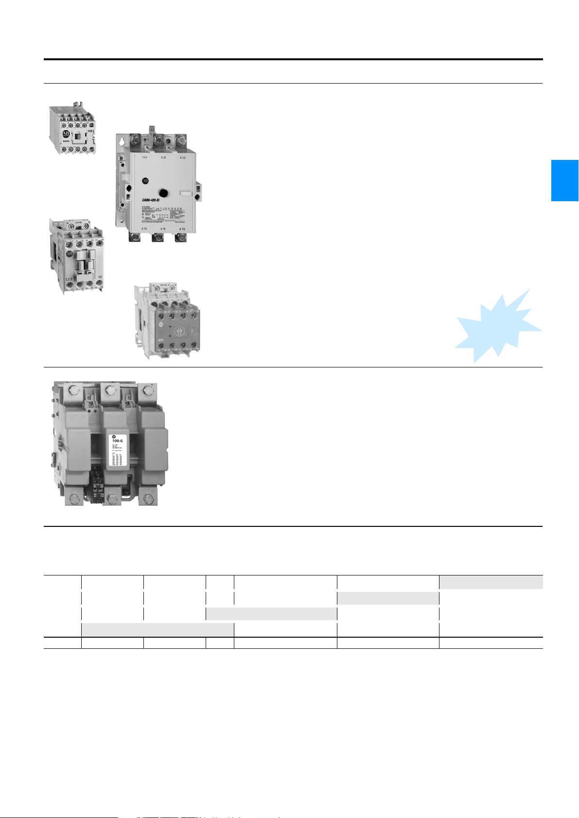
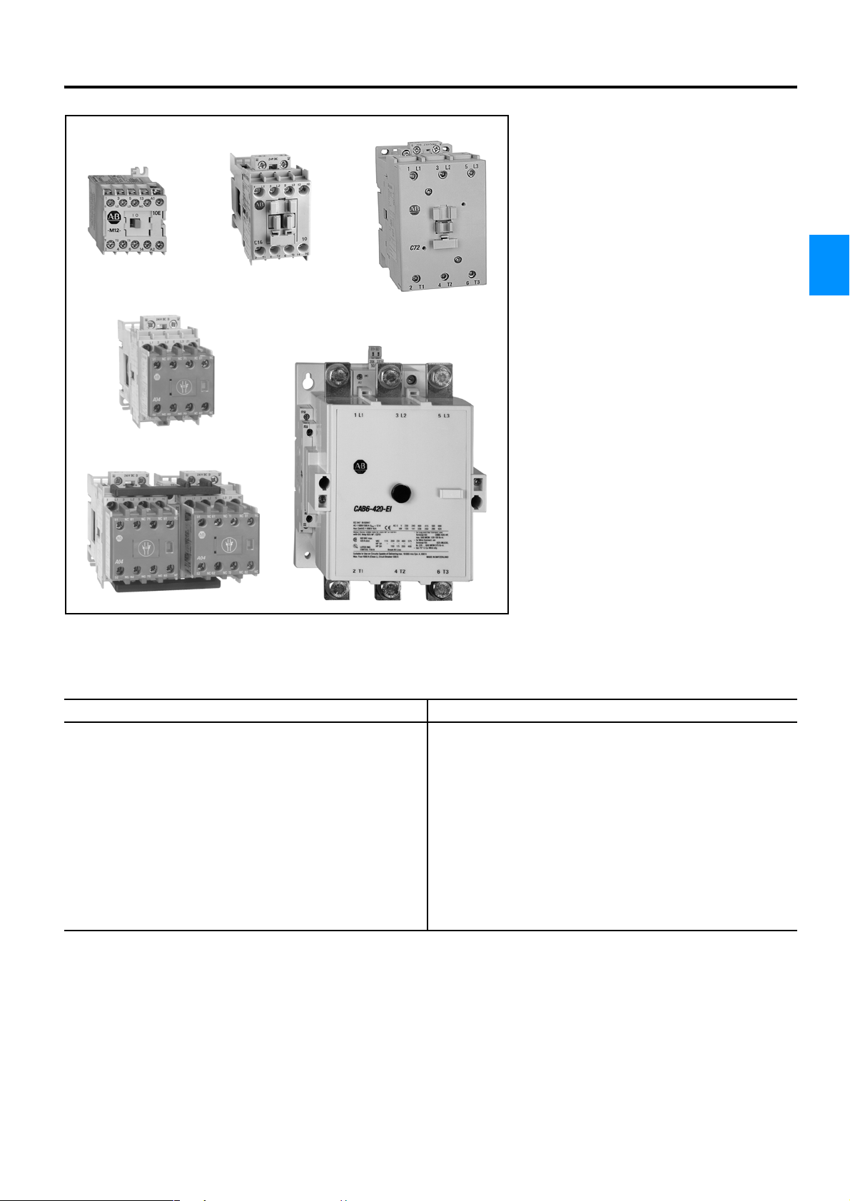
Bulletin 100-M, 100-C, 104-C, 100S-C, 104S-C, CAB6, 100-G
Contactors
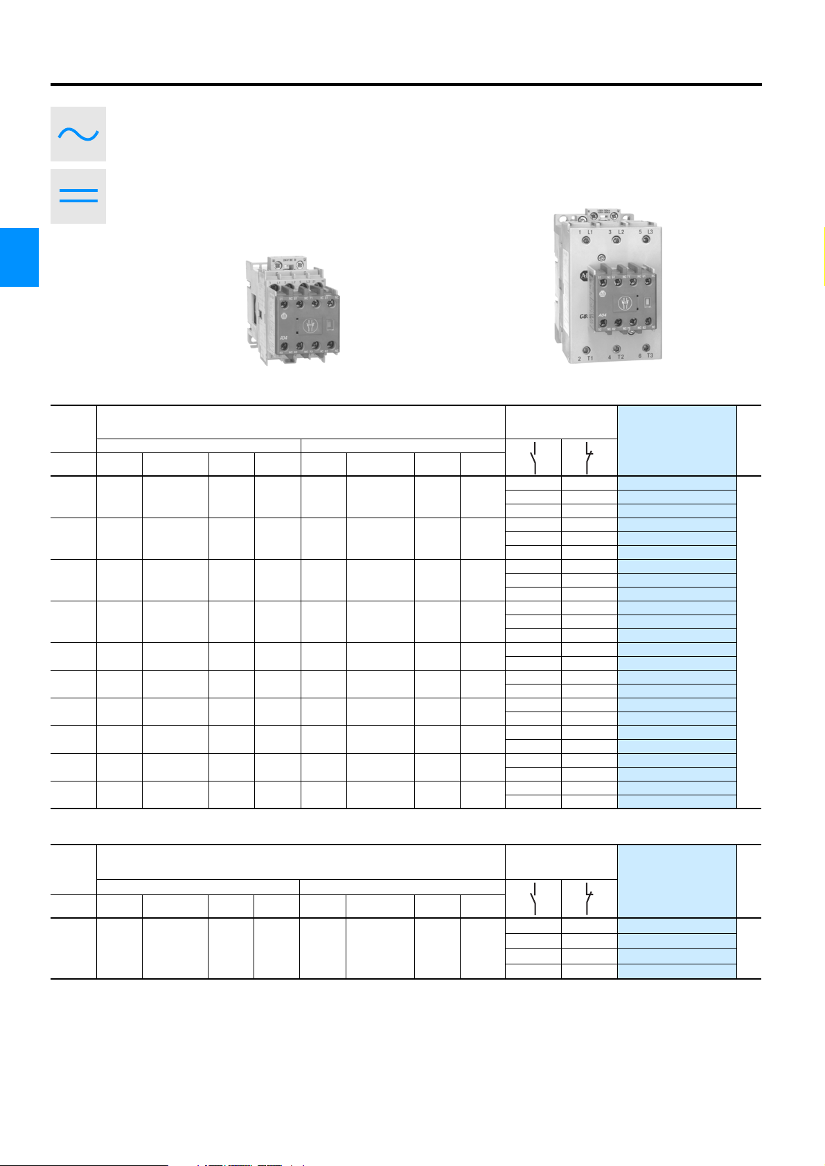
Bulletin 100-M, 100-C,
CAB6
Contactors
• Bulletin 100-M
2.2 … 5.5 kW
• Bulletin 100-C
4 … 45 kW
• Bulletin CAB6
45 … 220 kW
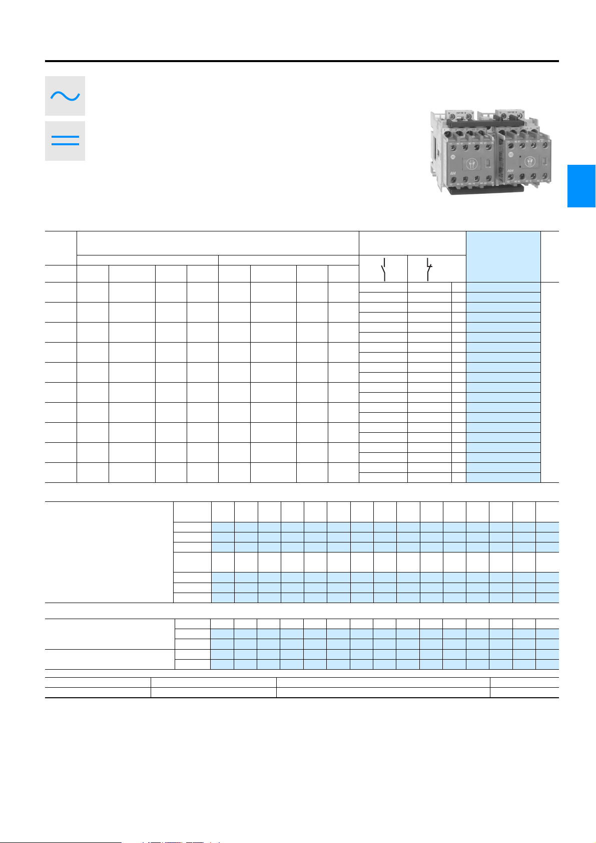
Bulletin 100S, 104S
Safety Contactors
• Bulletin 100S, 104S
4 … 45 kW
Bulletin 100-G
Contactors
Pages
4-9 … 4-64
w
e
N
Pages
4-65 … 4-78
4
• Bulletin 100-G
315 … 710 kW
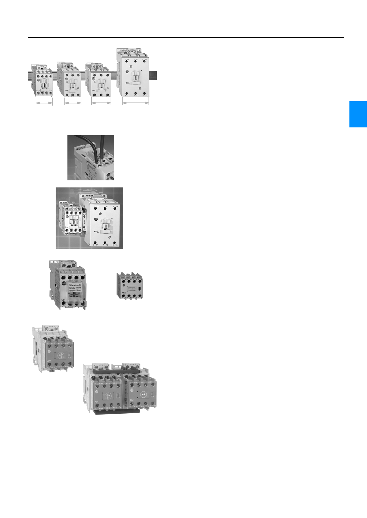
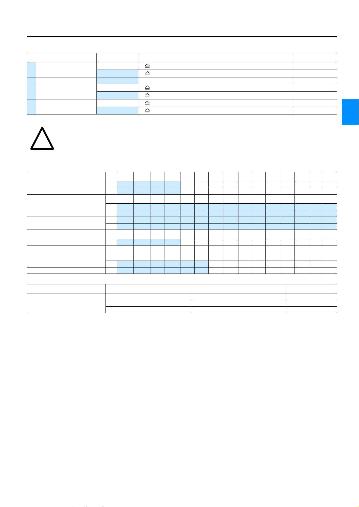
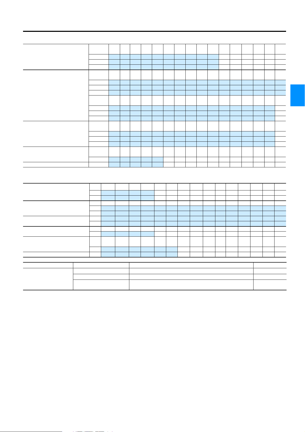
Contactor Overview
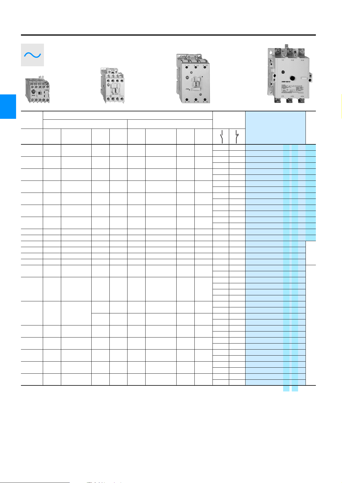
AC-3 / 400 VAC
100-G (550…1200 A)
CAB6 (85…420 A)
100-C (9…85 A)
100-M (5…12 A)
[kW] 2.2 4 5.5 45 220 710
Rockwell Automation 4-1
Page 2
Bulletin 100-M, 100-C, 104-C, 100S-C, 104S-C, CAB6, 100-G
Contactors
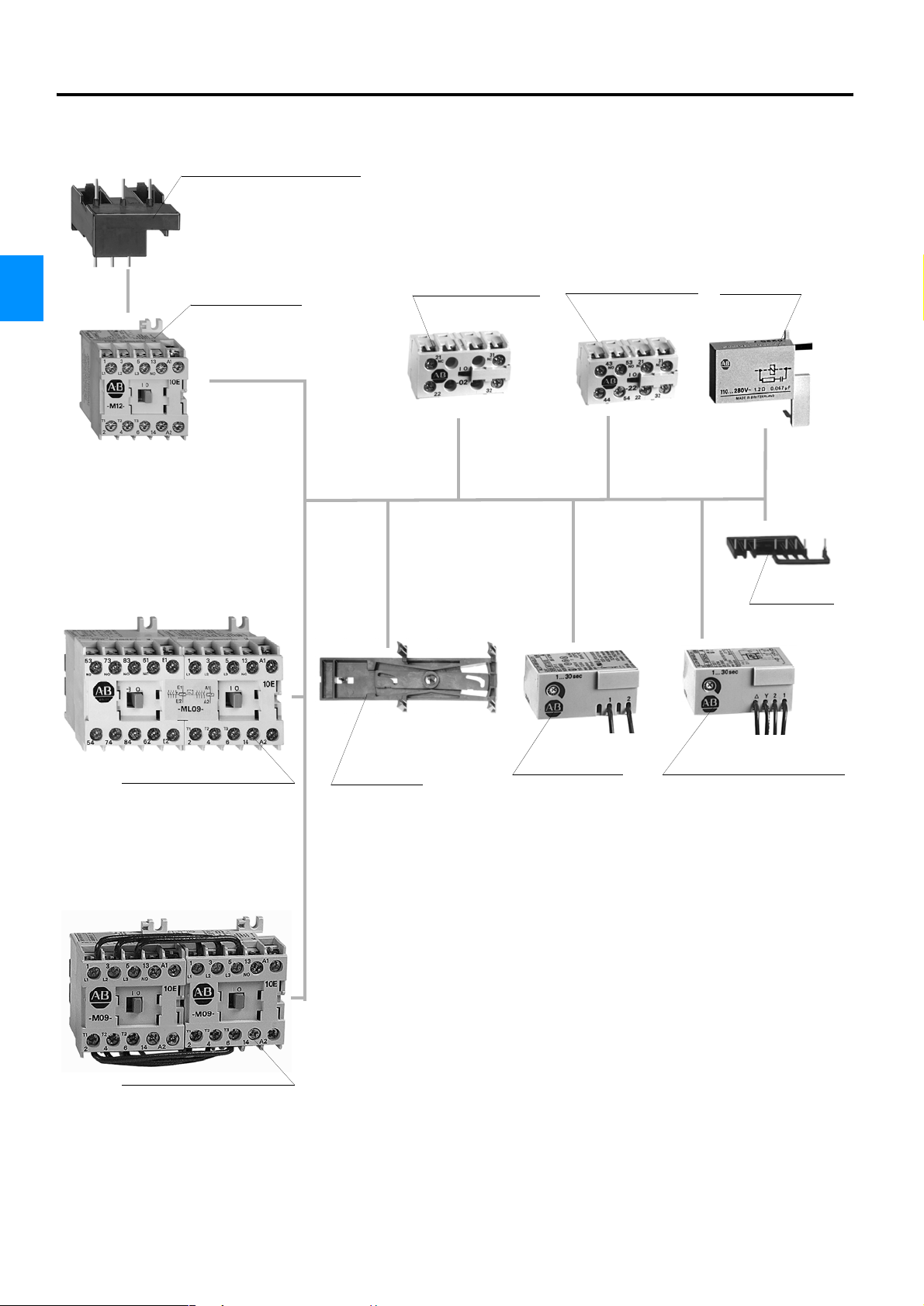
Overview - Bulletin 100-M
Connection module (Eco starter)
for circuit breakers 140M
4
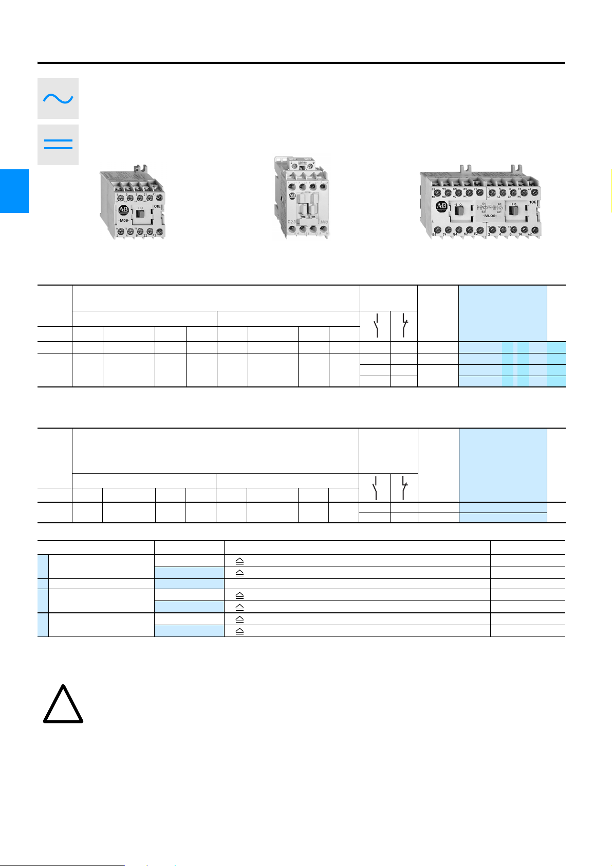
Miniature Contactor
100-M12N…
Auxiliary contact block
2 poles
Auxiliary contact block
4 poles
Suppressor module
RC, Diode,
Varistor
Connecting kit
Latched miniature contactor
100-ML09N…
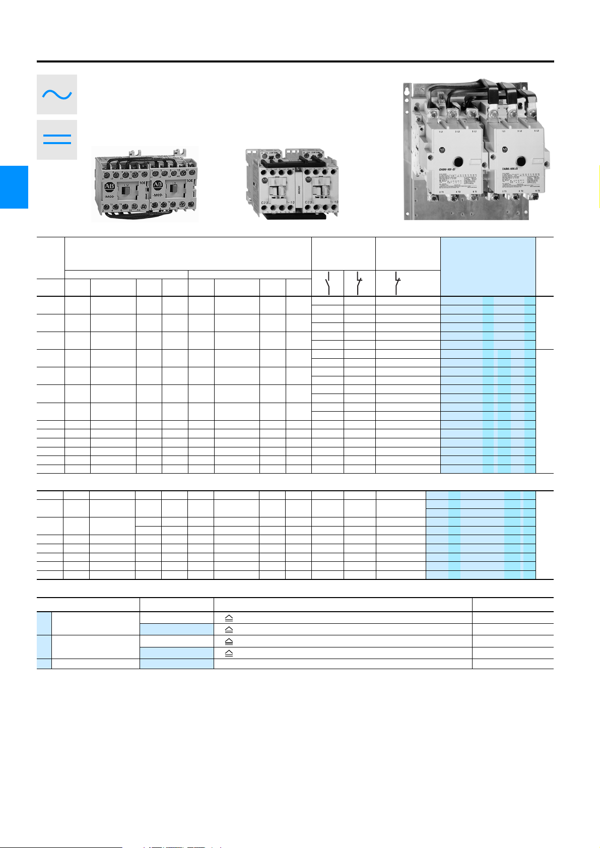
Reversing contactor
104-M
Mechanical
interlock
Timer
for pick-up delay
Timer for Y-∆ control
switching delay
4-2 Rockwell Automation
Page 3
Bulletin 100-M, 100-C, 104-C, 100S-C, 104S-C, CAB6, 100-G
Contactors
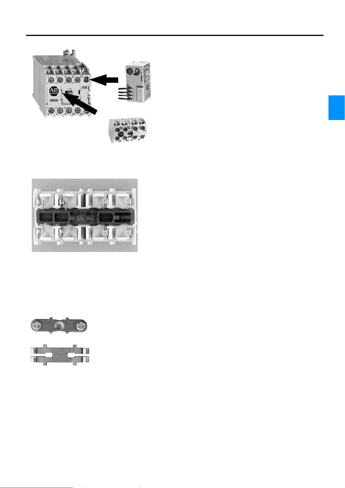
Overview - Bulletin 100-M
Minimum Space Requirements for Accessories
Auxiliary contact blocks and timers can be mounted onto the contactor
without requiring additional panel space.
4
Positive Guidance of the Contacts
Positive guidance of the contacts according to IEC 60947-5-1 is given
when it is ensured, that N.C. and N.O. contacts can never be closed at
the same time. Therefore a minimum opening distance of 0.5 mm is
prescribed in the event of failure. All contacts in the basic device are
positively guided as well as the normally closed contacts in the auxiliary
contact block except Bulletin 700-MB bifurcated contacts. This permits
use within safety controls.
High Contact Reliability
Bulletin 100-M Miniature Contactors are rated for extra-low voltage. In
addition to the isolation of the contact housing, high contact reliability is
ensured by the special design of the auxiliary contacts:
• cross-stamped in the main contactor
• in the auxiliary contact block and in the bifurcated contacts (see chapter 8, Bulletin 700-M timers), H-contact bridges with constant sliding
rolling motion and 4 multiple current path.
Rockwell Automation 4-3
Page 4
Bulletin 100-M, 100-C, 104-C, 100S-C, 104S-C, CAB6, 100-G
Contactors
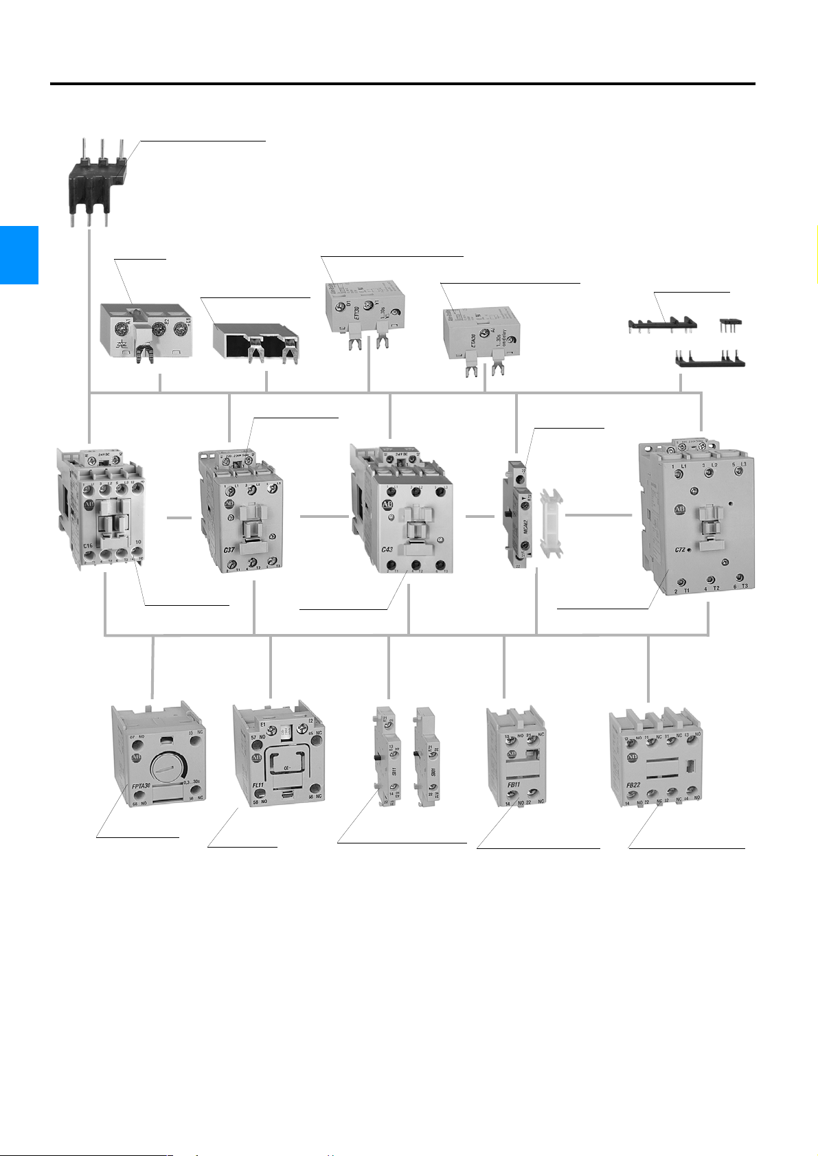
Overview - Bulletin 100-C
Connection module
for circuit breakers 140M
Solid-State timing module
4
Interface
Suppressor module
RC, Diode, Varistor
for Y-∆ control
switching delay
Solid-State timing module
pick-up delay
Connection set
Contactor
100-C09…C23
Contactor
100-C30, C37
Contactor
100-C43
Mechanical
interlock
Contactor
100-C60…C85
Pneumatic
timing module
Mechanical
latch
Auxiliary contact blocks
for side mounting
1- and 2-pole
Auxiliary contact blocks
for front mounting
2-pole
Auxiliary contact blocks
for front mounting
4-pole
4-4 Rockwell Automation
Page 5
Bulletin 100-M, 100-C, 104-C, 100S-C, 104S-C, CAB6, 100-G
Contactors
Overview - Bulletin 100-C, 100S-C
Compact design
Bulletin 100-C contactors switch more power and use less panel space. Despite
their small dimensions, they are powerful enough for use with the high starting
currents of today’s modern motors.
45 mm
9 A, 12 A,
16 A, 23 A
(AC-3 at 400/415 V)
45 mm
30 A,
37 A
54 mm
43 A
72 mm
60 A, 72 A,
85 A
4
Bulletin 100-C contactors for good connections
Two separate power connections per pole offer ease of wiring and high connection
reliability. The modern connection technology used by Bulletin 100-C contactors
saves both time and money.
Coil always positioned correctly
The dual connection technology always positions the coil connection for optimal
accessibility, whether below (on starters with circuit breakers), or above (on starters
using the revolutionary Bulletin 193-E Electronic Overload relay). Space- and costsaving coil modules (interface devices, protection elements, Electronic timers) can
always be added. When ordering, select the desired position of the coil connections. The position of the coil connections can also be adapted locally within seconds, using simple tools.
Uniform accessories for the entire line of contactors
All Bulletin 100-C accessories can be used with all contactor sizes.The mechanical
interlock with integrated interlock contacts can be used alone to interlock the smallest AC contactor with the largest.
Bulletin 100-C contactors for highest security
Bulletin 100-C contactors are rated for high personal protection and functional
security. The safety package consists of amongst other things
finger and back of hand accidental contact protection.
• Secure isolation of electric circuits
• Positively guided contacts
• Cover to prevent manual operation.
Comprehensive Safety for Operating Personnel and the Machine
The safety of both operators and machinery becomes more and more important.
Electrical controls can play an important contribution to safety. Various rules and
standards define the components and systems that are used in safety applications.
• Positively guided contacts according to IEC 947-5-1
• Fixed coupling of contactor and auxiliary contact block
• Protection against unintended actuation
• Auxiliary contacts that are electronically compatible according to DIN 19240
Positive Guidance of the Contacts
Positive guidance of contacts according to IEC 60947-5-1 is given when it
is ensured, that N.C. and N.O. contacts are never able to be closed at the same
time. Therefore a minimum opening distance of 0.5 mm is prescribed in the event
of failure. All contacts in the basic device are positively guided as well as the
normally closed contacts in the auxiliary contact block. The contacts in the basic
device as well as in the auxiliary contact blocks are guided restricted. The restricted
guidance also applies between basic device and accessories.
Rockwell Automation 4-5
Page 6
Bulletin 100-M, 100-C, 104-C, 100S-C, 104S-C, CAB6, 100-G
Contactors
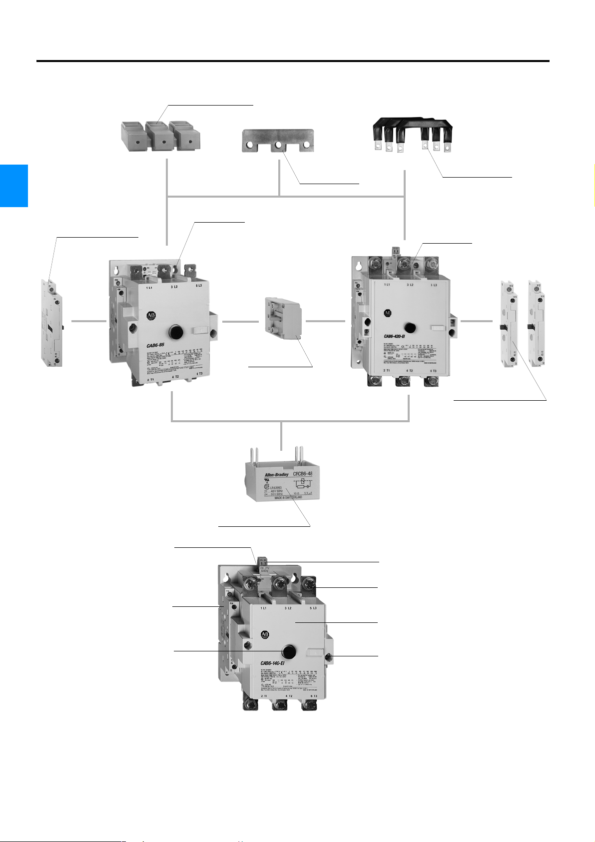
Overview - Bulletin CAB6
Terminal block
4
Contactor
Auxiliary contact block
CAB6-85…
Mechanical
interlock
Star Bridge
Contactor
CAB6-210…
Connection set
Auxiliary contact blocks
Easy-to-wire coil connections
Max. 2 auxiliary contacts per
side, left- and right-side mounted
Isolated switching position inhibits
manual operation
Suppressor module
RC, Diode, Varistor
Interface integrated with CAB6-105-EI
Threaded connections
Completely enclosed arcing chamber
Safety lock for arcing chamber and
contact holders
4-6 Rockwell Automation
Page 7
Bulletin 100-M, 100-C, 104-C, 100S-C, 104S-C, CAB6, 100-G
Contactors
Overview - Bulletin CAB6
Bulletin CAB6 Contactors with electronically controlled Coil Mechanism
Bulletin CAB6 contactors are equipped with electronically controlled coil mechanisms and integrated interface starting from size
CAB6-105-EI. Size CAB6-85 is equipped with conventional coils and sizes CAB6-105 and CAB6-140 can be equipped with either
conventional or electronic coils. Contactors with electronic coils are characterised by the -El suffix. By offering control options, a
multitude of possibilities are at the user's disposal:
• Integrated interface
The factory supplied CAB6-EI range features an interface module that can be
activated and deactivated via an externally accessible jumper unit. With the
interface, the contactor can be addressed directly by a 24 V DC signal from a
programmable logic controller. The max. allowable current of the interface is 15
mA (DIN VDE 19240). The Interface input is separated from the coil circuit by
photoelectric.
• Protective circuit included
All EI-type contactors have a protective circuit as standard.
• Low pick-up and holding power
When compared with conventional contactors, the current requirement is substantially lowered by the construction of the contactor, particularly via the electronic control.
4
CAB6-85…170
• Wide voltage range
Despite the wide voltage range (e.g., 208...277 V AC) the min./max. values of
the IEC tolerances are kept between -0.85 and +1.1.
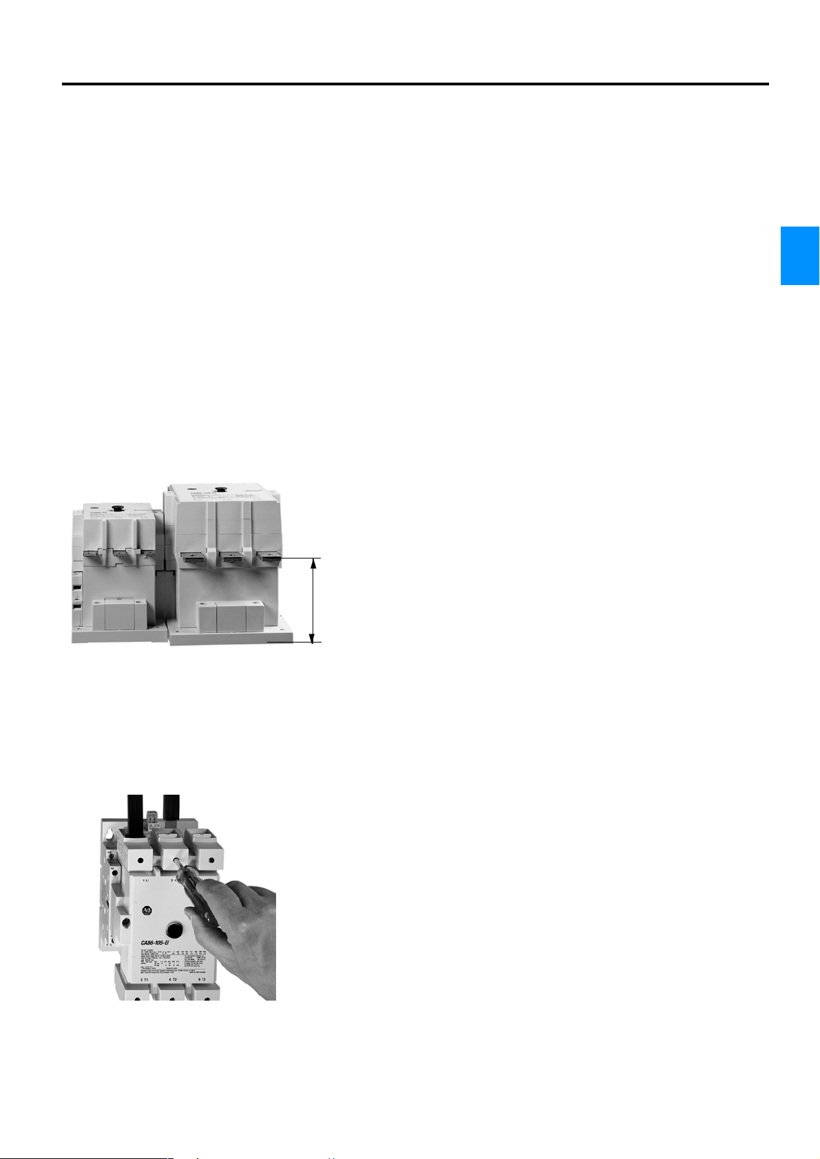
• Compact dimensions
New, compact construction solutions and the application of electronics substantially reduces the dimensions. Two housing sizes cover the entire range from
85...420 A (AC-3). Simple and efficient wiring is ensured by the identical connection height of the main pole on both housing sizes.
Bulletin CAB6 contactors can be mechanically interlocked, without needing additional mounting space.
110 mm
CAB6-210…420
• Defined on- and off- points
Electronic control guarantees defined points of switching on and off, thus preventing chatter and damage to the contactor.
• Environmentally friendly
Construction and contact materials do not contain cadmium, asbestos or PCBs
and can be recycled at the end of the contactor life. Most plastic parts are characterised according to DIN 54840.
• Frame terminal blocks
Go safe! Contact protection is fulfilled by attachable terminal covers according
to DIN VDE 0106 and VBG 4. By using framework terminal blocks the contactor
automatically becomes finger-safe per IP20.
Rockwell Automation 4-7
Page 8
Bulletin 100-M, 100-C, 104-C, 100S-C, 104S-C, CAB6, 100-G
Contactors
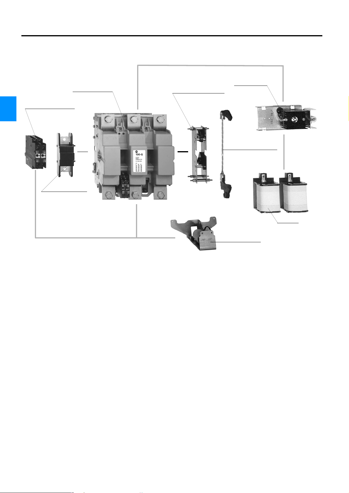
Overview - Bulletin 100-G / CA 5
Contactor
100-G / CA 5
4
Auxiliary contact block
Supply module
Mechanical interlock
(horizontal construction)
Mechanical interlock
(vertical construction)
Fourth pole
Coil sets
Mechanical latch
Good reasons to select Rockwell
Automation contactors
• Allen-Bradley contactors are built for a global marketplace
and fulfill all applicable IEC 947 requirements.
• Worldwide acceptance and high stock availability in all
countries increases security for the user.
• A wide range of accessories (e.g., auxiliary contact blocks,
interfaces, control and timing modules) make contactors
ideal and economical building blocks for individual
control needs.
4-8 Rockwell Automation
Page 9
Bulletin 100-M, 100-C, 104-C, 100S-C, 104S-C, CAB6
Contactors
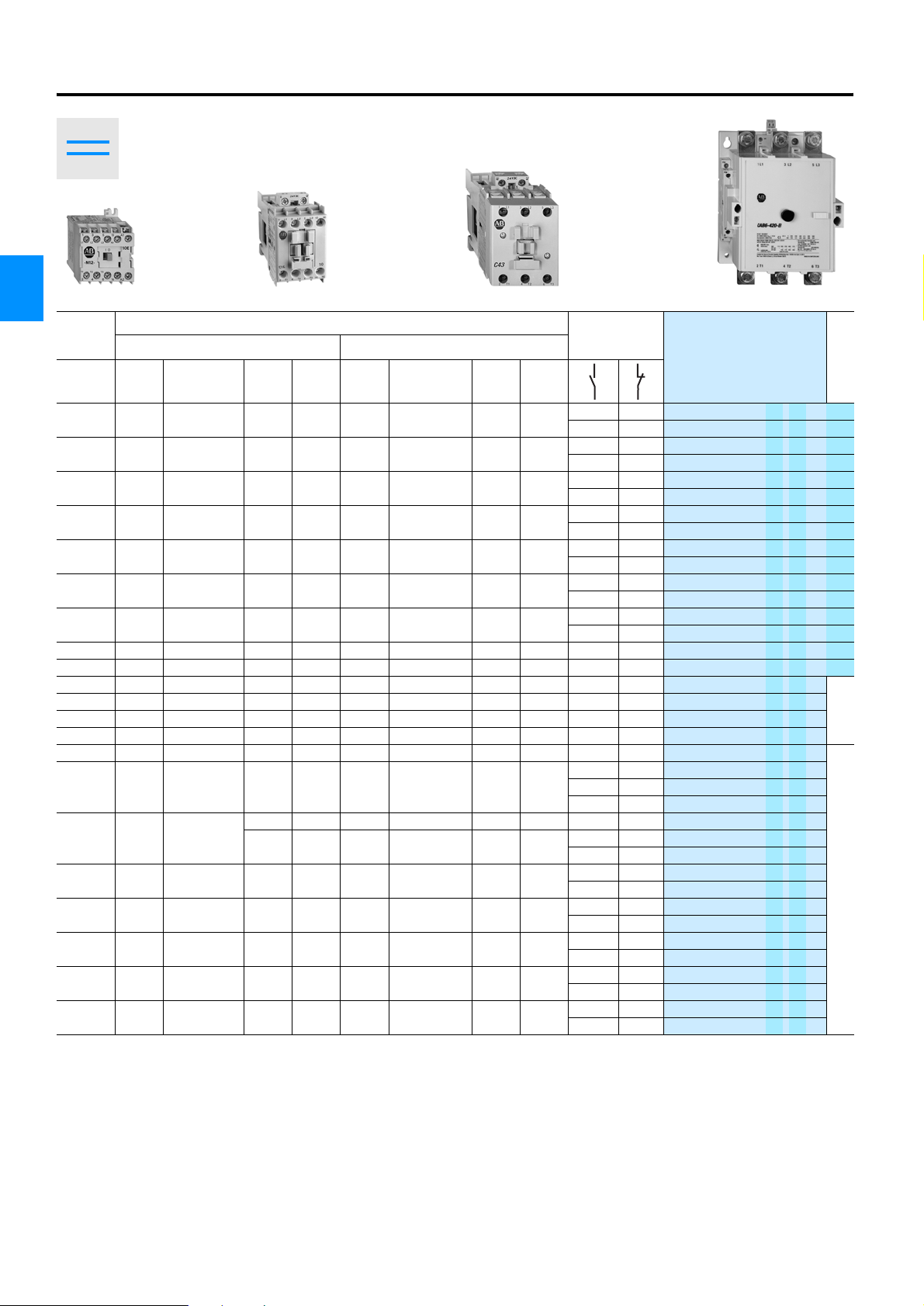
Bulletin 100-M
Miniature Contactors
• Bulletin 100-M
2.2 … 5.5 kW (5 … 12 A)
Bulletin 100-C, CAB6
Contactors
• Bulletin 100-C
4 … 45 kW (9 … 85 A)
• Bulletin 104-C
4 … 45 kW (9 … 85 A)
• Bulletin CAB6
45 … 220 kW (85 … 420 A)
Bulletin 100S, 104S
Safety Contactors
• Bulletin 100S-C
4 … 45 kW (9 … 85 A)
• Bulletin 104S-C
4 … 45 kW (9 … 85 A)
4
Table of Contents
Description Page Description Page
Overview . . . . . . . . . . . . . . . . . . . . . . . . . . . . . . . . . . . . . . . . . . . 4-2
Product Selection
AC Control . . . . . . . . . . . . . . . . . . . . . . . . . . . . . . . . . . . . . . . 4-10
DC Control . . . . . . . . . . . . . . . . . . . . . . . . . . . . . . . . . . . . . . . 4-12
Special Versions. . . . . . . . . . . . . . . . . . . . . . . . . . . . . . . . . . . 4-14
Reversing Contactors. . . . . . . . . . . . . . . . . . . . . . . . . . . . . . . 4-16
Safety Contactors. . . . . . . . . . . . . . . . . . . . . . . . . . . . . . . . . . 4-18
Accessories
Modules . . . . . . . . . . . . . . . . . . . . . . . . . . . . . . . . . . . . . . . . . 4-24
Mounting Materials . . . . . . . . . . . . . . . . . . . . . . . . . . . . . . . . . 4-31
Labelling Material . . . . . . . . . . . . . . . . . . . . . . . . . . . . . . . . . . 4-33
Renewal Parts . . . . . . . . . . . . . . . . . . . . . . . . . . . . . . . . . . . . 4-33
Specifications
Performance Data / Characteristics . . . . . . . . . . . . . . . . . . . . .4-36
Weight . . . . . . . . . . . . . . . . . . . . . . . . . . . . . . . . . . . . . . . . . . .4-44
Standards and Approvals. . . . . . . . . . . . . . . . . . . . . . . . . . . . .4-49
Electrical Data . . . . . . . . . . . . . . . . . . . . . . . . . . . . . . . . . . . . .4-51
Permissible Switching Rate . . . . . . . . . . . . . . . . . . . . . . . . . . .4-57
Dimensions . . . . . . . . . . . . . . . . . . . . . . . . . . . . . . . . . . . . . . . . .4-61
Rockwell Automation 4-9
Page 10
Bulletin 100-M, 100-C, 104-C, 100S-C, 104S-C, CAB6
Contactors
Product Selection
3-pole Contactors
• AC control
• 3 main contacts
4
100-M CAB6100-C 100-C
AC-1
(40 °C)
[A] 230 V 400 / 415 V 500 V 690 V 230 V 400 / 415 V 500 V 690 V
20 1.5 2.2 2.2 — 6.5 5.3 4 —
20 3 4 4 — 12 9 7 —
20 3 5.5 ➋ 4 — 12 12 ➋ 7—
32 3 4 4 4 12 9 7 5
32 4 5.5 5.5 5.5 15 12 10 7
32 5.5 7.5 7.5 7.5 20 16 14 9
32 7.5 11 13 10 26.5 23 20 12
50 10 15 15 15 35 30 25 18
50 11 18.5 / 20 20 18.5 38 37 30 21
85 13 22 25 22 44 43 38 25
10018.5 32 373262 60 5534
10022 40 454072 72 6742
10025 45 554585 85 8049
16025 45 558085 85 8585
160 32 55 63 100 105 105 105 105
250 45 75
250 55 90 / 100 110 160 170 170 170 170
350 63 110 150 200 210 210 210 210
350 80 132 / 150 160 250 250 250 250 250
450 90 160 200 300 300 300 300 300
500 132 220 / 250
Bulletin CAB contactors are suitable for use with operating voltages up to 1000V. Bulletin CAB6-...-El contactors are equipped with electronic coil control ⊕ ⊗
➊ Power ratings: Preferred values according to IEC 60072-1
➋ Value applies only to AC-2 and AC-3
➌ Value applies only to AC-2 and AC-3; AC-4: 360 A
Switching of 3-phase Motors AC-2, AC-3, AC-4 (60 °C)
[kW] ➊ [A]
80 110 140 140 115 115
90 132 140 140 140 140
300 ➌ 425 ➌
420 420
420 ➌ 420 ➌
Auxiliary
Contacts
Integrated
1 0 100-M05N ⊗ 3 ✪
0 1 100-M05N ⊗ 31 ✪
1 0 100-M09N ⊗ 3 ✪
0 1 100-M09N ⊗ 31 ✪
1 0 100-M12N ⊗ 3 ✪
0 1 100-M12N ⊗ 31 ✪
1 0 100-C09 ⊕ ⊗ 10 ✫
0 1 100-C09 ⊕ ⊗ 01 ✫
1 0 100-C12 ⊕ ⊗ 10 ✫
0 1 100-C12 ⊕ ⊗ 01 ✫
1 0 100-C16 ⊕ ⊗ 10 ✫
0 1 100-C16 ⊕ ⊗ 01 ✫
1 0 100-C23 ⊕ ⊗ 10 ✫
0 1 100-C23 ⊕ ⊗ 01 ✫
0 0 100-C30 ⊕ ⊗ 00 ✫
0 0 100-C37 ⊕ ⊗ 00 ✫
0 0 100-C43 ⊕ ⊗ 00
0 0 100-C60 ⊕ ⊗ 00
0 0 100-C72 ⊕ ⊗ 00
0 0 100-C85 ⊕ ⊗ 00
0 0 CAB6-85-00- ⊗
1 1 CAB6-85-11- ⊗
0 0 CAB6-105-00- ⊗
1 1 CAB6-105-11- ⊗
0 0 CAB6-105-EI-00- ⊗
1 1 CAB6-105-EI-11- ⊗
0 0 CAB6-140-00- ⊗
1 1 CAB6-140-11- ⊗
0 0 CAB6-140-EI-00- ⊗
1 1 CAB6-140-EI-11- ⊗
0 0 CAB6-170-EI-00- ⊗
1 1 CAB6-170-EI-11- ⊗
0 0 CAB6-210-EI-00- ⊗
1 1 CAB6-210-EI-11- ⊗
0 0 CAB6-250-EI-00- ⊗
1 1 CAB6-250-EI-11- ⊗
0 0 CAB6-300-EI-00- ⊗
1 1 CAB6-300-EI-11- ⊗
0 0 CAB6-420-EI-00- ⊗
1 1 CAB6-420-EI-11- ⊗
Cat. No. PQ
1
1
PQ = Package Quantity
Accessories - Page 4-24
Specifications - Page 4-36
Dimensions - Page 4-61
4-10 Rockwell Automation
Page 11
Bulletin 100-M, 100-C, 104-C, 100S-C, 104S-C, CAB6
Contactors
Product Selection
Selection of Options
Options Cat. No. Suffix Description Ordering Example
⊕ Coil connection position
⊗ Voltage suffix code e.g. KJ Voltage suffix code from table below 100-C09KJ10
✪ Package quantity 100-M
✫ Package quantity 100-C
Attention:
Bulletin 100-M…S: standard quantity = single item (1 piece)
!
Bulletin 100-C, CAB6: standard quantity = single item (1 piece)
⊗ Voltage Suffix Codes for AC Control
100-M
100-C
CAB6-85…CAB6-140 ➍
CAB6-105-EI…CAB6-250-E ➎
CAB6-300-EI…CAB6-420-EI ➎
No Entry Line-side coil connection (above, standard quantity) 100-C09⊗10
U Load-side coil connection (below) 100-C09U⊗10
No Entry Multi-pack (10 pieces) (Only KD, D, KF, KK) 100-M09N⊗3
S Single item (1 piece, standard quantity) 100-M09N⊗3S
No Entry Single item (1 piece, standard quantity) 100-C09⊗10
M Multi-pack (20 pieces) 100-C09⊗10M
[V] 24 48 110
50 Hz
60 Hz — — — D — — (A) — — KK
50/60 Hz KD KH — — KF — — (KT) — —
50 Hz
60 Hz (Q) (J) — (V) — (X) — (KP) — (D) — — (KG) — (L)
50/60 Hz
50 Hz
60 Hz — — — (A) (T) (I) (E) — — — (N) (B) — — (C)
50/60 Hz — KF — (KA) — — — — KN — (KB) — — — —
50 Hz
60 Hz
50/60 Hz — — — — (48) — — 54 (55) — — — — — —
50/60 Hz
50/60 Hz
— — D — — (A) — — KK
[V]122432 36 42 48100
(R) (K) (V) (W) (X) (Y) (KP) — (D) (P) (S) (KG) — — —
— KJ — — — KY (KP) — KD — — (KG) — (KL) —
220-
[V]
[V] 24 28 48 55 110 127
[V]
230
230
(F) — (VA) (T) — — — (N) — (G) (B) — (M) (C) —
05 — 08 — 10 — 13 — (15) — — 16 (17) — —
— 05 — 08 — 10 — — — 13 (15) — — 16 (17)
24-2843-65110-
05 08 10 14 16
— 08 10 14 16
110-
120
230-
240 277 347 380
240
208-
130
277
230
380-
400
220-
230
230-
240
220-
230
380-
240
400
100-
110 120 127 200
110
380-
400
400
230 240 260 277
400-
415
200-
220
400-
440 480 500 550 600
415
380-
415
400
200-
230
440-
460
208-
240
480
4
Price Adder for: Type Available Control Voltages No Surcharge
100-M 12…500 V 50 Hz, 12…600 V 60 Hz > 25 pieces
Special control voltages
CAB6-85…CAB6-140 ➍ 21…550 V 50 Hz, 21…575 V 60 Hz, 110…240 V 50/60 Hz > 25 pieces
( ) Control voltages in parentheses: No inventory
➍ 50/60 Hz coil only available for CAB6-85 and 105
➎ Signal voltage of the CAB6...EI electronic interface: U
100-C 12…600 V 50 Hz, 12…600 V 60 Hz > 20 pieces
: 24 VDC / Ie: 15 mA
e
Logical 1: 13.0 VDC…30.2 VDC
Logical 0: -3.0 VDC…+5.0 VDC
Accessories - Site 4-24
Specifications - Page 4-36
Dimensions - Page 4-61
Rockwell Automation 4-11
Page 12
Bulletin 100-M, 100-C, 104-C, 100S-C, 104S-C, CAB6
Contactors
Product Selection
3-pole Contactors
• DC control
• 3 main contacts
4
100-M..Z CAB6100-C..Z 100-C..Z
AC-1
(40 °C)
[A] 230 V 400 / 415 V 500 V 690 V 230 V 400 / 415 V 500 V 690 V
20 1.5 2.2 2.2 — 6.5 5.3 4 —
20344—1297—
20 3 5.5 ➋ 4—12 12 ➋ 7—
323444129 75
32 4 5.5 5.5 5.5 15 12 10 7
32 5.5 7.5 7.5 7.5 20 16 14 9
32 7.5 11 13 10 26.5 23 20 12
50 10 15 15 15 35 30 25 18 0 0
50 11 18.5 / 20 20 18.5 38 37 30 21 0 0 100-C37 ⊕ ⊗ 00 ✫
85 13 22 25 22 44 43 38 25 0 0 100-C43 ⊕ ⊗ 00
10018.5 32 373262 60 5534 0 0
10022 40 454072 72 6742 0 0 100-C72 ⊕ ⊗ 00
10025 45 554585 85 8049 0 0 100-C85 ⊕ ⊗ 00
16025 45 558085 85 8585
160 32 55 63 100 105 105 105 105
250 45 75
250 55 90 / 100 110 160 170 170 170 170
350 63 110 150 200 210 210 210 210
350 80 132 / 150 160 250 250 250 250 250
450 90 160 200 300 300 300 300 300
500 132 220 / 250 300 ➌ 425 ➌ 420 420 420 ➌ 420 ➌
Bulletin CAB contactors are suitable for use with operating voltages up to 1000V. Bulletin CAB6-...-El contactors are equipped with electronic coil control
➊ Power ratings: Preferred values according to IEC 60072-1
➋ Value applies only to AC-2 and AC-3
➌ Value applies only to AC-2 and AC-3; AC-4: 360 A
Switching of 3-phase Motors AC-2, AC-3, AC-4 (60 °C)
[kW] ➊ [A]
80 110 140 140 115 115 2 2 CAB6-140-L22- ⊗
90 132 140 140 140 140
Auxiliary
Contacts
Internal
1
0 1 100-M05N ⊗ 31 ✪
1
0 1 100-M09N ⊗ 31 ✪
1 0 100-M12N ⊗ 3 ✪
0
1 0 100-C09 ⊕ ⊗ 10 ✫
0 1 100-C09 ⊕ ⊗ 01 ✫
1
0 1 100-C12 ⊕ ⊗ 01 ✫
1 0 100-C16 ⊕ ⊗ 10 ✫
0
1 0 100-C23 ⊕ ⊗ 10 ✫
0 1 100-C23 ⊕ ⊗ 01 ✫
2 2 CAB6-85-L22- ⊗
2 2 CAB6-105-L22- ⊗
0 0 CAB6-105-EI-00- ⊗
1 1 CAB6-105-EI-11- ⊗
0 0 CAB6-140-EI-00- ⊗
1 1 CAB6-140-EI-11- ⊗
0 0 CAB6-170-EI-00- ⊗
1 1 CAB6-170-EI-11- ⊗
0 0 CAB6-210-EI-00- ⊗
1 1 CAB6-210-EI-11- ⊗
0 0 CAB6-250-EI-00- ⊗
1 1 CAB6-250-EI-11- ⊗
0 0 CAB6-300-EI-00- ⊗
1 1 CAB6-300-EI-11- ⊗
0 0 CAB6-420-EI-00- ⊗
1 1 CAB6-420-EI-11- ⊗
0 100-M05N ⊗ 3 ✪
0 100-M09N ⊗ 3 ✪
1 100-M12N ⊗ 31 ✪
0 100-C12 ⊕ ⊗ 10 ✫
1 100-C16 ⊕ ⊗ 01 ✫
Cat. No. PQ
100-C30 ⊕ ⊗ 00 ✫
100-C60 ⊕ ⊗ 00
1
1
PQ = Package Quantity
Accessories - Site 4-24
Specifications - Page 4-36
Dimensions - Page 4-61
4-12 Rockwell Automation
Page 13
Bulletin 100-M, 100-C, 104-C, 100S-C, 104S-C, CAB6
Contactors
Product Selection
Selection of Options
Options Cat. No. Suffix Description Ordering Example
⊕ Coil connection position
⊗ Voltage suffix code e.g. ZJ Voltage suffix code from table below 100-C09ZJ10
✪ Package quantity 100-M
✫ Package quantity 100-C
Attention:
Bulletin 100-M…S: standard quantity = single item (1 piece)
!
Bulletin 100-C, CAB6: standard quantity = single item (1 piece)
⊗ Voltage Suffix Codes for DC Control
100-M
with diode protection circuit DC ZD24 — —
100-C09…C43
with diode protection circuit DC — — DJ — — — — — — — — — — — —
100-C60…C85 DC — — — — — — — — — — — — — — —
with diode protection circuit DC (DR) (DQ) DJ (DW) (DY) (DZ) (DB) (DG) (DE) DD (DP) (DS) (DA) (DF) (DT)
CAB6-85…CAB6-140 ➏
CAB6-105-EI…CAB6-300-EI
CAB6-420-EI DC — (70) — 76 — (86)
No Entry Line-side coil connection (above, standard quantity) 100-C09⊗10
U Load-side coil connection (below) 100-C09U⊗10
No Entry Multi-pack (10 pieces) (Only Z24, ZD24) 100-M09N⊗3
S Single item (1 piece, standard quantity) 100-M09N⊗3S
No Entry Single item (1 piece, standard quantity) 100-C09⊗10
M Multi-pack (20 pieces) 100-C09⊗10M
[V] 24 48 110 220
DC
Z24 (Z48) Z11 (Z2)
[V] 9 ➍ 12 24 ➎ 36 48 60 64 72 80 110 115 125 220 230 250
DC
(ZR) (ZQ) ZJ (ZW) (ZY) (ZZ) (ZB) (ZG) (ZE) ZD (ZP) (ZS) (ZA) (ZF) (ZT)
[V] 24 48 110 220
DC
66 (70) 76 (86)
24-2848-7290-
[V]
66 (70) 76 — (86) —
DC
135
110-
135
170-
255
190-
255
4
Price Adder for: Type Available Control Voltages No Surcharge
100-M..Z 12…250 VDC > 25 pieces
Special control voltages
( ) Control voltages in parentheses: No inventory
➍ Extended operating limits 0.65…1.3 x U
➎ Extended operating limits 0.7…1.25 x U
➏ With conventional DC control, the pickup winding must be interconnected with the late-breaking auxiliary contacts
s
s
100-C..Z 12…250 VDC > 20 pieces
CAB6-85…CAB6-140 24…240 VDC > 25 pieces
Accessories - Page 4-24
Specifications - Page 4-36
Dimensions - Page 4-61
Rockwell Automation 4-13
Page 14
Bulletin 100-M, 100-C, 104-C, 100S-C, 104S-C, CAB6
Contactors
Product Selection
Special Versions
• AC / DC control
•
• 4-pole contactors
• Latched contactors
4
100-M
100-C
4-pole Contactors Bulletin 100-M, 100-C
AC-1
(40°C)
[A] 230 V 400 / 415 V 500 V 690 V 230 V 400 / 415 V 500 V 690 V
20 3 4 4 — 12 9 7 — 4 0 AC/DC
32 7.5 11 13 10 26.5 23 20 12
(4-pole 100-C09…C16 contactors available upon request)
Switching of 3-phase Motors AC-2, AC-3, AC-4 ➊ (60 °C)
[kW] ➋ [A]
Main Poles
(Fitted)
40AC/DC
31
22 100-C23 ⊕ ⊗ 200 ✫
Latched Contactors Bulletin 100-ML
Auxiliary
AC-1
(40°C)
[A] 230 V 400 / 415 V 500 V 690 V 230 V 400 / 415 V 500 V 690 V
20344—1297—
Switching of 3-phase Motors AC-2, AC-3, AC-4 (60 °C)
[kW] [A]
Contacts
Latched
Contactors
10 AC
01 AC
Available
Options
AC/DC ➌
Available
Options
100-ML
Cat. No. PQ
100-M09N ⊗ 4 ✪
100-C23 ⊕ ⊗ 400 ✫
100-C23 ⊕ ⊗ 300 ✫
Cat. No. PQ
100-ML09N⊗3
100-ML09N⊗31
1
Options Cat. No. Suffix Description Ordering Example
⊕ Coil connection position
⊗ Tension de commande e.g. KJ Voltage suffix code from table below 100-C23KJ400
✪ Package quantity 100-M
✫ Package quantity 100-C
➊ AC-4 value only for contact assembly with 3 resp, 4 N.O. contacts
➋ Power ratings: Preferred values according to IEC 60072-1
➌ No inventory
No Entry Line-side coil connection (above, standard quantity) 100-C23⊗400
U Load-side coil connection (below) 100-C23U⊗400
No Entry Multi-pack (10 pieces) (Only KD, D, KF, KK, Z24, ZD24) 100-M09N⊗4
S Single item (1 piece, standard quantity) 100-M09N⊗4S
No Entry Single item (1 piece, standard quantity) 100-C23⊗400
M Multi-pack (20 pieces) 100-C23⊗400M
Attention:
Bulletin 100-M…S: standard quantity = single item (1 piece)
!
PQ = Package Quantity
Accessories - Site 4-24
Specifications - Page 4-36
Dimensions - Page 4-61
Bulletin 100-C: standard quantity = single item (1 piece)
4-14 Rockwell Automation
Page 15
Bulletin 100-M, 100-C, 104-C, 100S-C, 104S-C, CAB6
Contactors
Product Selection
⊗ Voltage Suffix Codes for AC Control
110-
120
230-
240 277 347 380
240
100-M
100-C
[V] 24 48 110
50 Hz
60 Hz — — — D — — (A) — — KK
50/60 Hz
50 Hz
60 Hz (Q) (J) — (V) — (X) — (KP) — (D) — — (KG) — (L)
50/60 Hz — KJ — — — KY (KP) — KD — — (KG) — (KL) —
50 Hz
60 Hz — — — (A) (T) (I) (E) — — — (N) (B) — — (C)
50/60 Hz
— — D — — (A) — — KK
KD KH — — KF — — (KT) — —
[V]122432364248100
(R) (K) (V) (W) (X) (Y) (KP) — (D) (P) (S) (KG) — — —
220-
[V]
230
230
(F) — (VA) (T) — — — (N) — (G) (B) — (M) (C) —
— KF — (KA) — — — — KN — (KB) — — — —
⊗ Voltage Suffix Codes for DC Control
100-M
with diode protection circuit DC ZD24 — —
100-C09…C43
with diode protection circuit DC
100-C60…C85 DC — — — — — — — — — — — — — — —
with diode protection circuit DC (DR) (DQ) DJ (DW) (DY) (DZ) (DB) (DG) (DE) DD (DP) (DS) (DA) (DF) (DT)
[V] 24 48 110 220
DC
DC
Z24 (Z48) Z11 (Z2)
[V] 9 ➍ 12 24 ➎ 36 48 60 64 72 80 110 115 125 220 230 250
(ZR) (ZQ) ZJ (ZW) (ZY) (ZZ) (ZB) (ZG) (ZE) ZD (ZP) (ZS) (ZA) (ZF) (ZT)
— — DJ — — — — — — — — — — — —
230
220-
230
230-
240
380-
240
100-
110
380-
400
400-
400
415
110 120 127 200
400-
400
415
200-
200-
220
230
440 480 500 550 600
208-
240
4
Price Adder for: Type Available Control Voltages No Surcharge
Special control voltages
( ) Control voltages in parentheses: No inventory
➍ Extended operating limits 0.65…1.3 x U
➎ Extended operating limits 0.7…1.25 x U
100-M 12…500 V 50 Hz, 12…600 V 60 Hz, 12…250 VDC > 25 pieces
100-C 12…600 V 50 Hz, 12…600 V 60 Hz, 12…250 VDC > 20 pieces
s
s
Accessories - Page 4-24
Specifications - Page 4-36
Dimensions - Page 4-61
Rockwell Automation 4-15
Page 16
Bulletin 100-M, 100-C, 104-C, 100S-C, 104S-C, CAB6
Contactors
Product Selection
Reversing Contactors
• 3 main contacts, coil connections above
• Mechanical / Electrical interlock included
• Wiring set for main pole interconnection included
4
AC-1
(40°C)
[A] 230 V 400 / 415 V 500 V 690 V 230 V 400 / 415 V 500 V 690 V
20 1.5 2.2 2.2 — 6.5 5.3 4 —
20344—1297—
20 3 5.5 ➍ 4—12 12 ➍ 7—
32344412975
32 4 5.5 5.5 5.5 15 12 10 7
32 5.5 7.5 7.5 7.5 20 16 14 9
32 7.5 11 13 10 26.5 23 20 12
50 10 15 15 15 35 30 25 18 0 0 2
50 11 18.5 / 20 20 18.5 38 37 30 21 0 0 2
85 13 22 25 22 44 43 38 25 0 0 2
100 18.5 32 37 32 62 60 55 34 1 1 0 ➎
100 22 40 45 40 72 72 67 42 1 1 0 ➎
100 25 45 55 45 85 85 80 49 1 1 0 ➎
Bulletin CAB contactors are suitable for use with operating voltages up to 1000V. Bulletin CAB6-...-El contactors are equipped with electronic coil control
160 25 45 55 80 85 85 85 85 1 1 0
160 32 55 63 100 105 105 105 105 1 1 0
250 45 75
250 55 90 / 100 110 160 170 170 170 170 1 1 0
350 63 110 / 125 150 200 210 210 210 210 1 1 0
350 80 132 / 150 160 250 250 250 250 250 1 1 0
450 90 160 200 300 300 300 300 300 1 1 0
500 132 220 / 250 300 ➏ 425 ➏ 420 420 420 ➏ 420➏ 11 0
Switching of 3-phase Motors AC-2, AC-3, AC-4 (60 °C)
[kW] ➊ [A]
80 110 140 140 115 115 1 1 0
90 132 140 140 140 140 1 1 0
Auxiliary
Contact
per Contactor
10 0➋ ➌
01 0➋
10 0➋ ➌
01 0➋
10 0➋ ➌
01 0➋
10 0
01 0
10 2
01 0
10 2
01 0
10 2
01 0
Auxiliary
Contact
on Interlock
104-M05N ⊗ 3 ◆
104-M05N ⊗ 31 ◆
104-M09N ⊗ 3 ◆
104-M09N ⊗ 31 ◆
104-M12N ⊗ 3 ◆
104-M12N ⊗ 31 ◆
104-C09 ⊗ 10 -E ◆
104-C09 ⊗ 00 -E ◆
104-C12 ⊗ 10 -E ◆
104-C12 ⊗ 00 -E ◆
104-C16 ⊗ 10 -E ◆
104-C16 ⊗ 00 -E ◆
104-C23 ⊗ 10 -E ◆
104-C23 ⊗ 00 -E ◆
104-C30 ⊗ 00 -E ◆
104-C37 ⊗ 00 -E ◆
104-C43 ⊗ 00 -E ◆
104-C60 ⊗ 10 -E ◆
104-C72 ⊗ 10 -E ◆
104-C85 ⊗ 10 -E ◆
CAU ✤ B6-85- 10 ⊗
CAU ✤ B6-105- 10 ⊗
CAU ✤ B6-105-EI- 10 ⊗
CAU ✤ B6-140- 10 ⊗
CAU ✤ B6-140-EI- 10 ⊗
CAU ✤ B6-170-EI- 10 ⊗
CAU ✤ B6-210-EI- 10 ⊗
CAU ✤ B6-250-EI- 10 ⊗
CAU ✤ B6-300-EI- 10 ⊗
CAU ✤ B6-420-EI- 10 ⊗
Cat. No. PQ
1
1
1
Options Cat. No. Suffix Description Ordering Example
◆ Mechanical interlock
✤ Mechanical interlock
⊗ Voltage suffix code e.g. KJ Voltage suffix code from the table on the next page 104-M05NKJ3
➊ Power ratings: Preferred values according to IEC 60072-1
➋ DC-control only available without mechanical interlock
➌ For electronic interlock additional N.C. contacts required
PQ = Package Quantity
Accessories - Page 4-24
Specifications - Page 4-36
Dimensions - Page 4-61
No Entry with mechanical interlock (standard) 104-M05N⊗3
-X without mechanical interlock 104-M05N⊗3-X
No Entry without mechanical interlock (standard) CAU-B6-105-EI-10⊗
M with mechanical interlock CAUMB6-105-EI-10⊗
➍ Value applies only to AC-2 and AC-3
➎ Bulletin 100-MCA00 mechanical interlock. Electrical interlock via the
front mounted auxiliary contact block (2 pole)
➏ Value applies only to AC-2 and AC-3; AC-4: 360 A
4-16 Rockwell Automation
Page 17
⊗ Voltage Suffix Codes for AC Control
[V] 24 48 110
104-M
104-C
CAUB6-85…CAUB6-140 ➐
CAUB6-105-EI…CAUB6-250-EI
CAUB6-300-EI…CAUB6-420-EI 50/60 Hz
50 Hz — — D — — (A) — — KK
60 Hz — — — D — — (A) — — KK
50/60 Hz
50 Hz
60 Hz
50/60 Hz
50 Hz
60 Hz
50/60 Hz
50 Hz
60 Hz
50/60 Hz
50/60 Hz
KD KH — — KF — — (KT) — —
[V]122432 36 42 48100
(R) (K) (V) (W) (X) (Y) (KP) — (D) (P) (S) (KG) — — — —
(Q) (J) — (V) — (X) — (KP) — (D) — — (KG) — (H) (L)
— KJ — — — KY (KP) — KD — — (KG) — (KL) — —
220-
[V]
230
(F) — (VA) (T) — — — (N) — (G) (B) — (M) (C) —
— — — (A) (T) (I) (E) — — — (N) (B) — — (C)
— KF — (KA) — — — — KN — (KB) — — — —
[V] 24 28 48 55 110 127
05 — 08 — 10 — 13 — (15) — — 16 (17) — —
— 05 — 08 — 10 — — — 13 (15) — — 16 (17)
— — — — (48) — — 54 (55) — — — — — —
24-2843-65110-
[V]
05 08 10 14 16
— 08 10 14 16
230
110-
230
120
230-
240 277 347 380
240
208-
277
380-
400
130
Bulletin 100-M, 100-C, 104-C, 100S-C, 104S-C, CAB6
Contactors
Product Selection
220-
230
230-
240
220-
230
380-
240
100-
110
380-
400
230 240 260 277
400-
400
415
110 120 127 200
400-
400
440 480 500 550 600
415
380-
400
200-
220
415
200-
230
440-
460
208
480
208-
240
4
⊗ Voltage Suffix Codes for DC Control
104-M
with diode protection circuit DC
104-C09…C43
with diode protection circuit DC
104-C60…C85 DC
with diode protection circuit DC
CAB6-85…CAB6-140
CAB6-105-EI…CAB6-300-EI
CAB6-420-EI DC
Price Adder for: Type Available Control Voltages No Surcharge
Special control voltages
CAUB6-85…CAUB6-140 ➐
( ) Control voltages in parentheses: No inventory
E Wiring per IEC standard
➐ 50/60 Hz coils for CAB6-140 contactor not available
➑ Extended operating limits 0.65…1.3 x U
➒ Extended operating limits 0.7…1.25 x U
[V] 24 48 110 220
Z24 (Z48) Z11 (Z2)
DC
ZD24 — —
[V] 9 ➑ 12 24 ➒ 36 48 60 64 72 80 110 115 125 220 230 250
DC
(ZR) (ZQ) ZJ (ZW) (ZY) (ZZ) (ZB) (ZG) (ZE) ZD (ZP) (ZS) (ZA) (ZF) (ZT)
— — DJ — — — — — — — — — — — —
— — — — — — — — — — — — — — —
(DR) (DQ) DJ (DW) (DY) (DZ) (DB) (DG) (DE) DD (DP) (DS) (DA) (DF) (DT)
[V] 24 48 110 220
DC
DC
66 (70) 76 (86)
24-2848-7290-
[V]
66 (70) 76 — (86) —
— (70) — 76 — (86)
104-M 12…500 V 50 Hz, 12…600 V 60 Hz, 12…250 VDC > 25 pieces
104-C 12…600 V 50 Hz, 12…600 V 60 Hz, 12…250 VDC > 20 pieces
s
s
110-
170-
135
135
21…550 V 50 Hz, 21…575 V 60 Hz, 110…240 V 50/60 Hz,
255
190-
255
24…240 VDC
> 25 pieces
Accessories - Page 4-24
Specifications - Page 4-36
Dimensions - Page 4-61
Rockwell Automation 4-17
Page 18
Bulletin 100-M, 100-C, 104-C, 100S-C, 104S-C, CAB6
Contactors
Product Selection
Safety Contactors
• AC / DC control
• 3 / 4 main contacts
• Positively guided contacts according to IEC 947-5-1
• Mechanically coupled Contactor and Auxiliary contact block
• Protection against unintended actuation
• Auxiliary contacts are electronically compatible according to
4
With 3 Main Contacts
AC-1
(40°C)
[A] 230 V 400 / 415 V 500 V 690 V 230 V 400 / 415 V 500 V 690 V
32 3 4 4 4 11.5 9 7 5
32 4 5.5 5.5 5.5 14.5 12 10 7
32 5.5 7.5 7.5 7.5 20 16 / 15 13 9.3
32 7.5 11 11 10 24 23 / 22 18 12
50 10 15 15 15 34 30 / 29 24 17
50 11 18.5 18.5 18.5 37 37 / 36 30 20
85 13 22 22 22 42 43 / 41 34 25
100 18.5 30 30 30 62 60 / 58 45 34
100 22 37 37 37 70 72 / 69 56 42
100 25 45 45 45 85 85 / 82 67 49
DIN 19240
Switching of 3-phase Motors AC-2, AC-3, AC-4 (60 °C)
[kW] ➊ [A]
Positively Guided
Auxiliary Contacts
05
14
23
05
14
23
05
14
23
05
14
23
04
22
04
22
04
22
04
22
04
22
04
22
Cat. No. PQ
100S-C09⊗05C
100S-C09⊗14C
100S-C09⊗23C
100S-C12⊗05C
100S-C12⊗14C
100S-C12⊗23C
100S-C16⊗05C
100S-C16⊗14C
100S-C16⊗23C
100S-C23⊗05C
100S-C23⊗14C
100S-C23⊗23C
100S-C30⊗04C
100S-C30⊗22C
100S-C37⊗04C
100S-C37⊗22C
100S-C43⊗04C
100S-C43⊗22C
100S-C60⊗04C
100S-C60⊗22C
100S-C72⊗04C
100S-C72⊗22C
100S-C85⊗04C
100S-C85⊗22C
1
With 4 Main Contacts
AC-1
(40°C)
[A] 230 V 400 / 415 V 500 V 690 V 230 V 400 / 415 V 500 V 690 V
32 7.5 11 11 10 24 23 / 22 18 12
PQ = Package Quantity
Accessories - Page 4-24
Specifications - Page 4-36
Dimensions - Page 4-61
Switching of 3-phase Motors AC-2, AC-3, AC-4 (60 °C)
[kW] ➊ [A]
Positively Guided
Auxiliary Contacts
04
04
22100S-C23⊗422C
22100S-C23⊗322C
Cat. No. PQ
100S-C23⊗404C
100S-C23⊗304C
1
4-18 Rockwell Automation
Page 19
Bulletin 100-M, 100-C, 104-C, 100S-C, 104S-C, CAB6
Reversing-Safety Contactors
• AC / DC control
• 3 main contacts, coil connections above
• Positively guided contacts acc. to IEC 947-5-1
• Mechanically coupled Contactor and Auxiliary contact block
• Protection against unintended actuation
• Auxiliary contacts are electronically compatible according
• to DIN 19240
• Mechanical / Electrical interlock included
• Wiring set for main pole interconnection included
With 3 Main Contacts
AC-1
(40°C)
[A] 230 V 400 / 415 V 500 V 690 V 230 V 400 / 415 V 500 V 690 V
32 3 4 4 4 11.5 9 7 5
32 4 5.5 5.5 5.5 14.5 12 10 7
32 5.5 7.5 7.5 7.5 20 16 / 15 13 9.3
32 7.5 11 11 10 24 23 / 22 18 12
50 10 15 15 15 34 30 / 29 24 17
50 11 18.5 18.5 18.5 37 37 / 36 30 20
85 13 22 22 22 42 43 / 41 34 25
100 18.5 30 30 30 62 60 / 58 45 34
100 22 37 37 37 70 72 / 69 56 42
100 25 45 45 45 85 85 / 82 67 49
Switching of 3-phase Motors AC-2, AC-3, AC-4 (60 °C)
[kW] ➊ [A]
⊗ Voltage Suffix Codes for AC Control
[V]122432364248100
100S-C. 104S-C
50 Hz
60 Hz
50/60 Hz
50 Hz
60 Hz
50/60 Hz
(R) (K) (V) (W) (X) (Y) (KP) — (D) (P) (S) (KG) — — —
(Q) (J) — (V) — (X) — (KP) — (D) — — (KG) — (L)
— KJ — — — KY (KP) — KD — — (KG) — (KL) —
220-
[V]
230
(F) — (VA) (T) — — — (N) — (G) (B) — (M) (C) —
— — — (A) (T) (I) (E) — — — (N) (B) — — (C)
— KF — (KA) — — — — KN — (KB) — — — —
230
230-
240 277 347 380
240
⊗ Voltage Suffix Codes for DC Control
100S-C09…C43, 104S-C09…C43
with diode protection circuit DC
100S-C60…C85, 104S-C60…C85 DC
with diode protection circuit DC
[V] 9 ➌ 12 24 ➍ 36 48 60 64 72 80 110 115 125 220 230 250
DC
(ZR) (ZQ) ZJ (ZW) (ZY) (ZZ) (ZB) (ZG) (ZE) ZD (ZP) (ZS) (ZA) (ZF) (ZT)
— — DJ — — — — — — — — — — — —
— — — — — — — — — — — — — — —
(DR) (DQ) DJ (DW) (DY) (DZ) (DB) (DG) (DE) DD (DP) (DS) (DA) (DF) (DT)
Positively Guided
Aux. contact per Contactor
05➋
05
05➋
05
05➋
05
05➋
05
04➋
04
04➋
04
04➋
04
04➋
04
04➋
04
04➋
04
100-
110 120 127 200
110
380-
400
400
400-
440 480 500 550 600
415
Contactors
Product Selection
Cat. No. PQ
104S-C09⊗012C
104S-C09⊗010C
104S-C12⊗012C
104S-C12⊗010C
104S-C16⊗012C
104S-C16⊗010C
104S-C23⊗012C
104S-C23⊗010C
104S-C30⊗010C
104S-C30⊗008C
104S-C37⊗010C
104S-C37⊗008C
104S-C43⊗010C
104S-C43⊗008C
104S-C60⊗010C
104S-C60⊗008C
104S-C72⊗010C
104S-C72⊗008C
104S-C85⊗010C
104S-C85⊗008C
200-
200-
220
230
1
208-
240
4
Price Adder for: Type Available Control Voltages No Surcharge
Special control voltages 100S-C. 104S-C 12…600 V 50 Hz, 12…600 V 60 Hz, 12…250 VDC > 20 pieces
( ) Control voltages in parentheses: No inventory
➊ Power ratings: Preferred values according to IEC 60072-1
➋ With mechanical and electrical locking 100-MCA02
➌ Extended operating limits 0.65…1.3 x U
➍ Extended operating limits 0.7…1.25 x U
s
s
Accessories - Page 4-24
Specifications - Page 4-36
Dimensions - Page 4-61
Rockwell Automation 4-19
Page 20
Bulletin 100-M, 100-C, 104-C, 100S-C, 104S-C, CAB6
Contactors
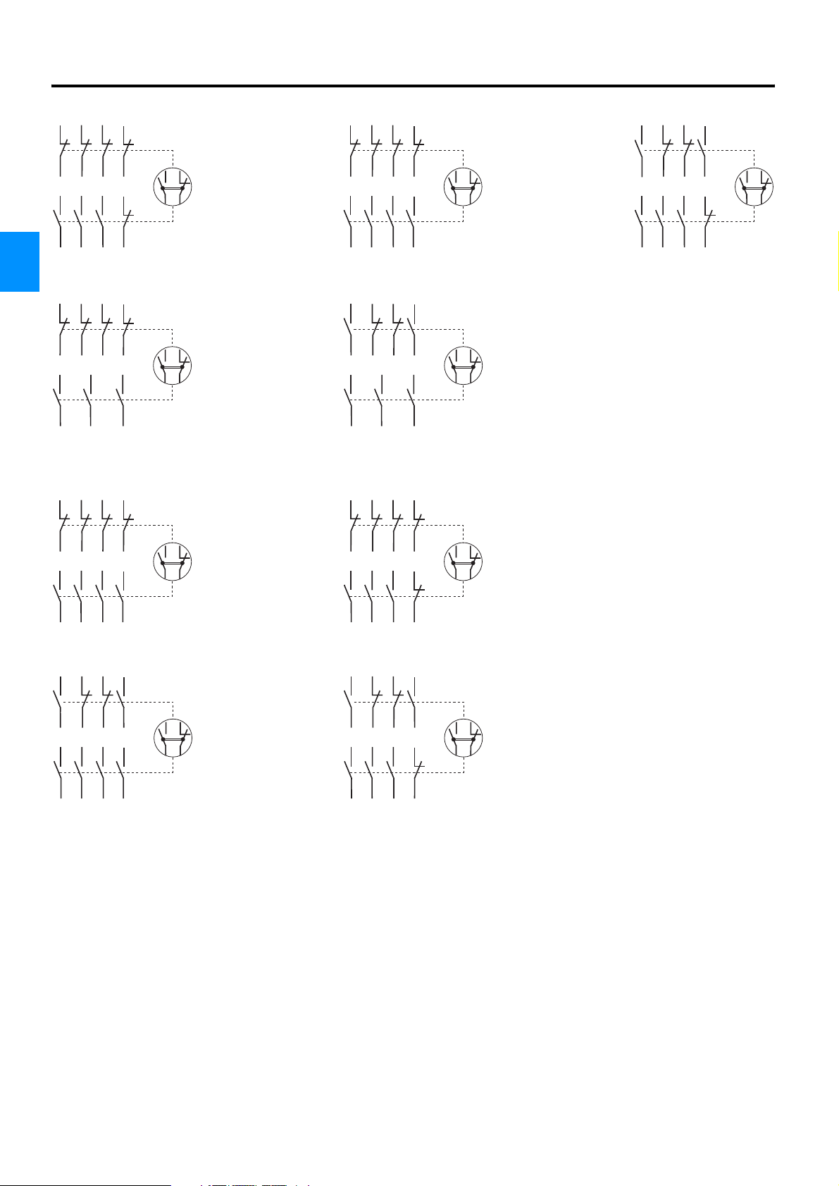
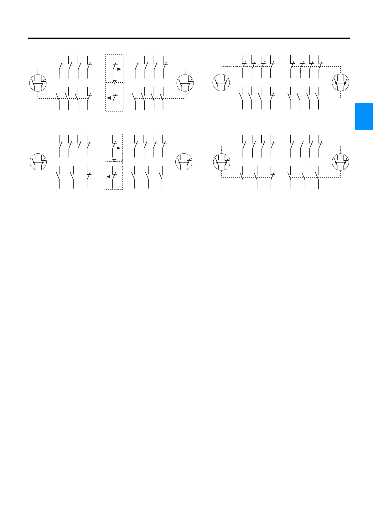
Assignment of Contacts
Contactors with 3 Main Contacts
71
51
81
51
71
81
53
71
83
626172
5
436
31
222132
436
82
21
22
41
42
5
52
1
2
100S-C09⊗05C…C23⊗05C 100S-C09⊗14C…C23⊗14C 100S-C09⊗23C…C23⊗23C
4
11
12
1
2
100S-C30⊗04C…C85⊗04C 100S-C30⊗22C…C85⊗22C
52
1
2
13
14
1
2
626172
5
436
31
222132
436
82
13
14
43
44
5
54
1
2
626172
436
Contactors with 4 Main Contacts
11
1
12
31
222132
5
41
42
7
11
12
1
31
222132
5
41
42
R1
84
5
21
22
436
31
222132
5
436
8
43
44
7
8
2
100S-C23⊗404C 100S-C23⊗304C
13
14
1
2
100S-C23⊗422C 100S-C23⊗322C
2
13
14
1
2
436
31
222132
5
436
R2
43
44
R1
R2
Product Selection - Page 4-10
4-20 Rockwell Automation
Page 21
Reversing-Safety Contactors with 3 Main Contacts
51
71
81
21
51
71
81
Bulletin 100-M, 100-C, 104-C, 100S-C, 104S-C, CAB6
Contactors
Assignment of Contacts
51
71
81
51
71
81
52
1
2
626172
436
82
5
21
22
626172
436
82
5
21
22
104S-C09⊗012C…C23⊗012C 104S-C09⊗010C…C23⊗010C
22
21
22
1
52
2
626172
5
436
82
21
22
52
1
2
1
52
2
626172
5
436
82
21
22
4
51
52
1
2
71
81
626172
82
3
5
4
6
104S-C30⊗010C…C85⊗010C 104S-C30⊗008C…C85⊗008C
21
22
21
22
51
52
1
2
71
626172
3
4
81
5
82
6
51
52
1
2
71
626172
3
4
81
82
5
6
51
1
52
2
71
626172
3
4
81
82
5
6
Product Selection - Page 4-10
Rockwell Automation 4-21
Page 22
Bulletin 100-M, 100-C, 104-C, 100S-C, 104S-C, CAB6
2
2
1
Contactors
Assignment of Contacts
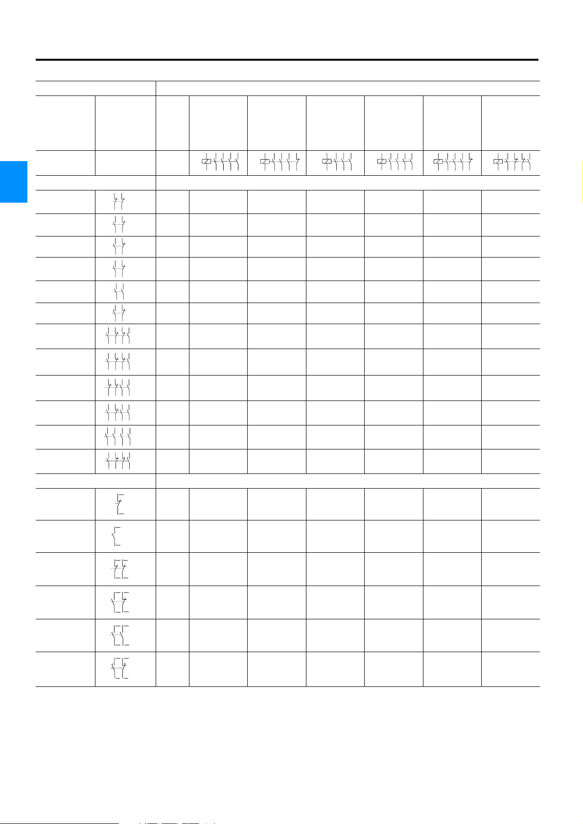
Device Combinations in Accordance with EN Standards
Auxiliary Contact Blocks Contactors 100-C (AC / DC Control)
100-C30⊕⊗00
5
13
14
100-C09⊕⊗01
100-C12⊕⊗01
100-C16⊕⊗01
100-C23⊕⊗01
1
A1
K1
A2
436
2
100-C09⊕⊗10
Circuit Diagram Control
100-C12⊕⊗10
100-C16⊕⊗10
100-C23⊕⊗10
1
A1
K1
A2
436
2
Front-mounted ➊
4
61
100-FA02 AC / DC 10 + 02 = 12 01 + 02 = 03 00 + 02 = 02 00 + 02 = 02 00 + 02 = 02 00 + 02 = 02
100-FA11 AC / DC 10 + 11 = 21 01 + 11 = 12 00 + 11 = 11 00 + 11 = 11 00 + 11 = 11 00 + 11 = 11
100-FB11 AC / DC — — 00 + 11 = 11 00 + 11 = 11 00 + 11 = 11 00 + 11 = 11
100-FC11 AC / DC10 + 11 = 2101 + 11 = 12————
100-FA20 AC / DC 10 + 20 = 30 01 + 20 = 21 00 + 20 = 20 00 + 20 = 20 00 + 20 = 20 00 + 20 = 20
100-FBL11 ➋ AC / DC — — 00 + 11 = 11 00 + 11 = 11 00 + 11 = 11 00 + 11 = 11
100-FA22 AC / DC 10 + 22 = 32 01 + 22 = 23 00 + 22 = 22 00 + 22 = 22 00 + 22 = 22 00 + 22 = 22
100-FB22 AC / DC — — 00 + 22 = 22 00 + 22 = 22 00 + 22 = 22 00 + 22 = 22
100-FC22 AC / DC10 + 22 = 32—————
100-FA31 AC / DC 10 + 31 = 41 01 + 31 = 32 00 + 31 = 31 00 + 31 = 31 00 + 31 = 31 00 + 31 = 31
100-FA40 AC / DC 10 + 40 = 50 01 + 40 = 41 00 + 40 = 40 00 + 40 = 40 00 + 40 = 40 00 + 40 = 40
100-FAL22 ➋ AC / DC 10 + 22 = 32 01 + 22 = 23 00 + 22 = 22 00 + 22 = 22 00 + 22 = 22 00 + 22 = 22
51
62
52
61
53
62
54
21
13
22
14
31
23
32
24
53
63
54
64
5
17
26
18
71
83
53
626172
84
54
31
43
13
222132
44
14
43
53
21
323144
54
22
73
83
53
626174
84
54
73
83
53
646374
84
54
75
87
53
626176
88
54
Side-mounted ➊
21
32
100-SB01 AC / DC 10 + 01 = 11 01 + 01 = 02 ➌ 00 + 01 = 01 00 + 01 = 01 00 + 01 = 01 00 + 01 = 01
100-SB10 AC / DC 10 + 10 = 20 ➌ 01 + 10 = 11 00 + 10 = 10 00 + 10 = 10 00 + 10 = 10 00 + 10 = 10
100-SB02 AC / DC 10 + 02 = 12 ➌ — 00 + 02 = 02 00 + 02 = 02 00 + 02 = 02 00 + 02 = 02
100-SB11 AC / DC 10 + 11 = 21 ➌ 01 + 11 = 12 ➌ 00 + 11 = 11 00 + 11 = 11 00 + 11 = 11 00 + 11 = 11
100-SB20 AC / DC 10 + 20 = 30 ➌ 01 + 20 = 21 ➌ 00 + 20 = 20 00 + 20 = 20 00 + 20 = 20 00 + 20 = 20
100-SBL11 ➋ AC / DC 10 + 11 = 21 ➌ 01 + 11 = 12 ➌ 00 + 11 = 11 00 + 11 = 11 00 + 11 = 11 00 + 11 = 11
22
13
44
14
43
4232
121122
41
4432
141322
43
4434
141324
43
7
48
18
47
31
21
31
21
31
23
33
25
36
26
35
5
21
2
100-C37⊕⊗00
100-C43⊕⊗00
100-C60⊕⊗00
100-C72⊕⊗00
100-C85⊕⊗00
1
A1
K1
A2
436
2
100-C23⊕⊗400 100-C23⊕⊗300 100-C23⊕⊗200
5
1
5
A1
K1
A2
7
436
8
2
1
R1
5
A1
K1
A2
43R2
2
K1
6
A1
A2
1
R1
43R2
R4R32
Product Selection - Page 4-10
4-22 Rockwell Automation
Page 23
Bulletin 100-M, 100-C, 104-C, 100S-C, 104S-C, CAB6
Device Combinations in Accordance with EN Standards
Auxiliary Contact Block Miniature Contactor 100-M (AC / DC Control)
Circuit Dia-
gram
Control
100-M05N⊗3
100-M09N⊗3
100-M12N⊗3
1
A1
K1
A2
436
2
100-M09N⊗4
5
13
14
1
5
A1
K1
A2
436
2
Front-mounted
31
195-MB02 AC / DC 10 + 02 = 12 40 + 02 = 42 —
195-MB11 AC / DC 10 + 11 = 21 40 + 11 = 51 —
195-MA20 AC / DC 10 + 20 = 30 40 + 20 = 60 01 + 20 = 21
195-MB22 AC / DC 10 + 22 = 32 40 + 22 = 62 —
21
32
22
33
222134
53
63
54
64
21
31
43
545322
32
44
73
83
53
195-MA40 AC / DC 10 + 40 = 50 40 + 40 = 80 01 + 40 = 41
646374
84
54
7
8
100-M05N⊗31
100-M09N⊗31
100-M12N⊗31
1
5
A1
K1
A2
436
2
21
22
Contactors
Assignment of Contacts
4
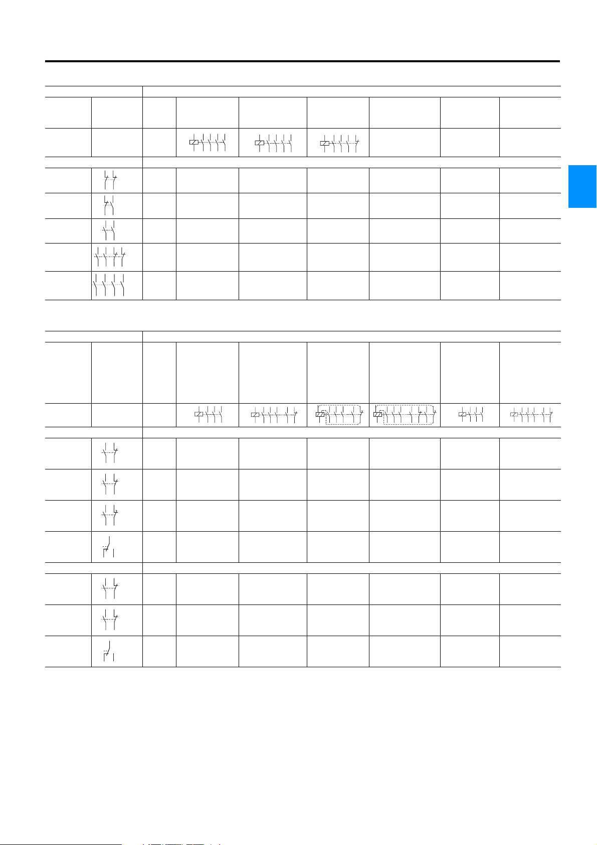
Auxiliary Contact Block Contactors CAB6 (AC / DC Control)
CAB6-140-EI-00⊗
Circuit
Diagram
Control
CAB6-85-00⊗
CAB6-105-00⊗
CAB6-140-00⊗
CAB6-85-11⊗
CAB6-105-11⊗
CAB6-140-11⊗
CAB6-85-L11⊗
CAB6-105-L11⊗
CAB6-140-L11⊗
CAB6-85-L22⊗
CAB6-105-L22⊗
CAB6-140-L22⊗
CAB6-170-EI-00⊗
CAB6-210-EI-00⊗
CAB6-250-EI-00⊗
CAB6-300-EI-00⊗
CAB6-420-EI-00⊗
1
5
A1
K1
436
A2
2
1
13
5
436
21
14
22
A1
K1
A2
2
1
B1
A1
K1
A2
2
436
35
43
5
44
1
5
B1
A1
1
A2
36
436
2
35
43
13
21
14
22
K1
44
36
Right-side mounted
31
CAB6-P2-11
CAB6-P4-11
CAB6-P2-L11 ➋ACDC
43
32
44
71
83
72
84
35
43
44
36
31
AC
DC
AC / DC
AC
DC
AC / DC
AC / DC
CAB6-P2-B11 ➍ACDC
3432
AC / DC
00 + 11 = 11
—
—
00 + 11 = 11
—
—
00+ 11 = 11
—
—
00+ 11 =11
—
—
11 + 11 = 22
—
—
11 + 11 = 22
—
—
11 + 11 = 22
—
—
11 + 11 = 22
—
—
—
11+ 11 = 22
—
—
11 + 11 = 22
—
—
11 + 11 = 22
—
—
11 + 11 = 22
—
—
22 + 11 = 33
—
—
22 + 11 = 33
—
—
22 + 11 = 33
—
—
22 + 11 = 33
—
00 + 11 = 11
00 + 11 = 11
00 + 11 = 11
00 + 11 = 11
Left-side mounted
AC
DC
AC / DC
AC
DC
AC / DC
CAB6-P1-11
CAB6-P3-11
21
13
22
14
61
53
62
54
61
CAB6-P3-B11 ➍ACDC
6462
➊ Up to 8 auxiliary contacts possible: Contactor + Front-mounted (AC max. 4 N.C:/DC max. 4 N.C.), Side-mounted
(AC max. 2 N.O./DC max. 2 N.O. and max. 2 N.C.)
AC / DC
00 + 11 = 11
—
—
00 + 11 = 11
—
—
00 + 11 = 11
—
—
11 + 11 = 22
—
—
11 + 11 = 22
—
—
11 + 11 = 22
—
—
—
11 + 11 = 22
—
—
11 + 11 = 22
—
—
11 + 11 = 22
—
—
22 + 11 = 33
—
—
22 + 11 = 33
—
—
22 + 11 = 33
—
00 + 11 = 11
00 + 11 = 11
00+ 11 = 11
➋ Early make and/or late break
➌ Double numbering: Because of double numbering only left-side mounting is recommended
➍ Electronically suited auxiliary contact block
CAB6-140-EI-11⊗
CAB6-170-EI-11⊗
CAB6-210-EI-11⊗
CAB6-250-EI-11⊗
CAB6-300-EI-11⊗
CAB6-420-EI-11⊗
1
5
A1
A2
436
2
—
—
1
13
5
A1
K1
A2
21
14
436
22
2
—
—
11 + 11 = 22
—
—
—
—
11 + 11 = 22
—
—
—
—
11 + 11 = L22
—
—
—
—
11 + 11 = 22
—
—
—
—
11 + 11 = 22
—
—
—
—
11 + 11 = 22
—
—
—
—
11 + 11 = 22
Product Selection - Page 4-10
Rockwell Automation 4-23
Page 24
Bulletin 100-M, 100-C, 104-C, 100S-C, 104S-C, CAB6
Contactors
Accessories
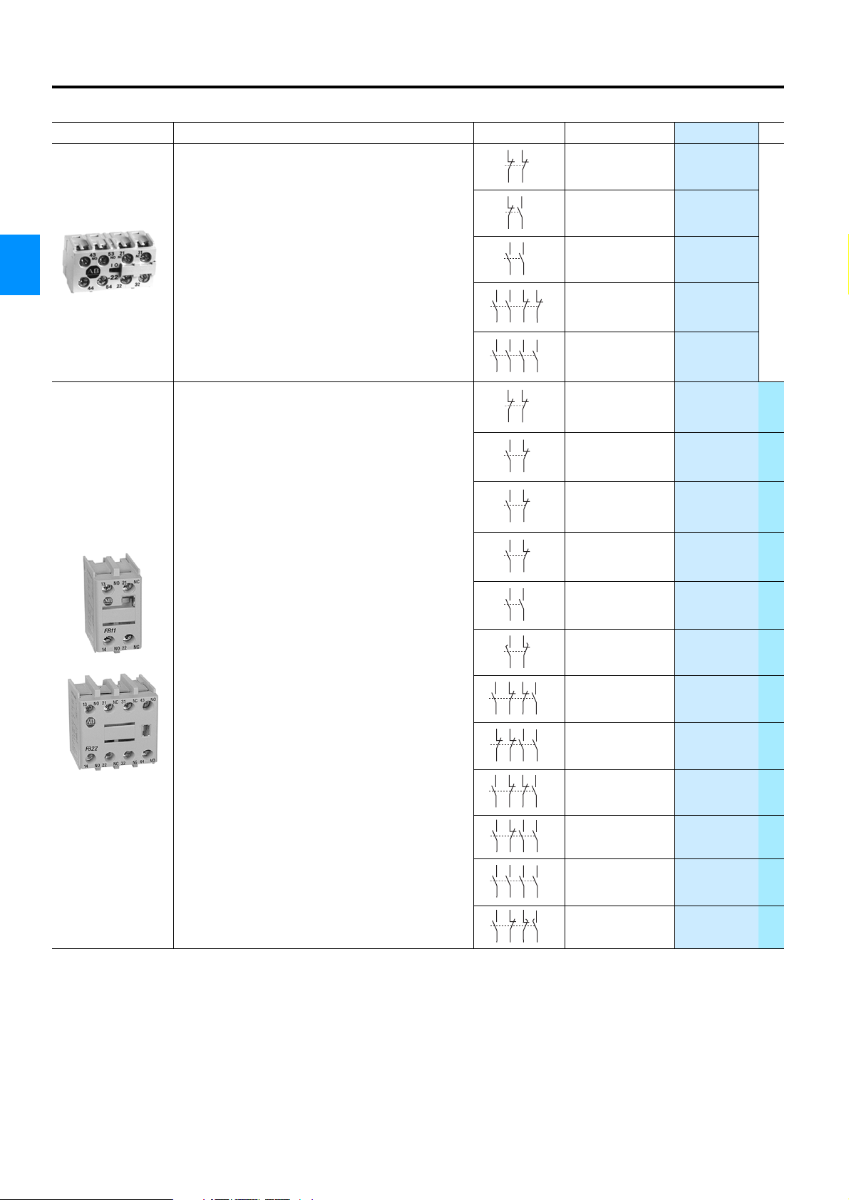
Modules: Auxiliary Contact Blocks
Description Circuit Diagram For Use with Cat. No. PQ
Auxiliary Contact Blocks for Front Mounting
• 2- and 4-pole
• Simple and quick attachment - no tools needed
4
• Electronically compatible H-contacts
• Contacts themselves in auxiliary contact block
positively guided
• Types with the same functions with several connection
numbering variants
Auxiliary Contact Blocks for Front Mounting ➊
• 2- and 4-pole
• Simple and quick attachment - no tools needed
• Electronically compatible contacts
• Positive guidance in auxiliary and with main contactor
poles (excluding type L)
• Types with the same functions with several connection
numbering variants
L = Early Make/Late Break
31
21
32
22
33
222134
53
63
54
64
21
31
43
545322
32
44
73
83
53
646374
84
54
61
51
62
52
61
53
62
54
21
13
22
14
31
23
32
24
53
63
54
64
25
17
26
18
71
83
53
626172
84
54
43
53
21
323144
54
22
31
43
13
222132
44
14
73
83
53
626174
84
54
73
83
53
646374
84
54
75
87
53
626176
88
54
100-M…3
100-M
100-M
100-M…3,
100-M…4
100-M
100-C
100-C
C30⊗00…C85⊗00
C09⊗10…C23⊗10
100-C
C30⊗00…C85⊗00
100-C
C09⊗10…C23⊗10
C30⊗00…C85⊗00
100-C
100-C
100-C
195-MB02
195-MB11
195-MA20
195-MB22
195-MA40
100-FA02 ✫
100-FA11 ✫
100-FB11 ✫
100-FC11 ✫
100-FA20 ✫
100-FBL11 ✫
100-FA22 ✫
100-FC22 ✫
100-FB22 ✫
100-FA31 ✫
100-FA40 ✫
100-FAL22 ✫
10
PQ = Package Quantity
Product Selection - Page 4-10
4-24 Rockwell Automation
Page 25

Modules: Auxiliary Contact Blocks
13
Description
Bulletin 100-M, 100-C, 104-C, 100S-C, 104S-C, CAB6
Contactors
Accessories
Circuit
Diagram
21
32
22
31
For Use with
100-C
Cat. No. PQ
100-SB01 ✫
Auxiliary Contact Blocks for Side Mounting ➊
• 1- and 2-pole
• Dual numbering for left- or right-side mounting on contactor
• Simple and quick attachment - no tools needed
• Electronically compatible contacts
• Positive guidance in auxiliary and with main contactor poles
(excluding type L)
L = Early Make/Late Break
Auxiliary Contact Blocks
• Up to 4 auxiliary contact blocks per contactor: P1 and P3
left, P2 and P4 right
• With mechanical interlock — 2 auxiliary contact blocks per
contactor, 1 left and 1 right
• No change of base dimensions with 1 auxiliary contact
block on each side
• Electronically compatible auxiliary contacts
AC-1 250 V
0.1 A
AC-15, DC-13 3 … 125 V
1 … 100 mA
44
14
43
4232
121122
41
4432
141322
43
4434
141324
43
17
48
18
47
13
14
43
44
53
54
83
84
43
44
31
3432
61
6462
100-C,
100S-C ➋
100-SB10 ✫
4
21
100-C ➋
31
21
100-C ➋
31
23
100-C,
33
25
36
100S-C ➋
100-C ➋
26
35
21
CAB6
Left-side
22
31
mounting
CAB6
Right-side
32
61
mounting
CAB6
Left-side
62
71
mounting
CAB6
Right-side
72
35
mounting
CAB6
Right-side
36
mounting
CAB6
Right-side
mounting
CAB6
Left-side
mounting
100-SB02 ✫
100-SB11 ✫
100-SB20 ✫
100-SBL11 ✫
CAB6-P1-11
CAB6-P2-11
CAB6-P3-11
CAB6-P4-11
CAB6-P2-L11
CAB6-P2-B11
CAB6-P3-B11
10
Options Cat. No. Suffix Description Ordering Example
✫ Package quantity
No Entry Single pack (1 piece, standard quantity) 100-SB10.
M Multi-pack (10 pieces) 100-SB10M
➊ Up to 8 auxiliary contacts possible: Contactor + Front-mounted (AC max. 4 N.C:/DC max. 4 N.C.), Side-mounted
(AC max. 2 N.O./DC max. 2 N.O. and max. 2 N.C.)
➋ Double numbering: Because of double numbering 100-C09
… 100-C23 only left-side mounting is recommended
PQ = Package Quantity
Product Selection - Page 4-10
Rockwell Automation 4-25
Page 26

Bulletin 100-M, 100-C, 104-C, 100S-C, 104S-C, CAB6
Contactors
Accessories
Modules: Timer
Electronic Star-Delta Timing Relay
Output Y picks up when the supply voltage is applied and resets again after time t.
After a fixed changeover time t
the supply voltage is interrupted.
• 22.5 mm width
4
Supply Voltage (A1/A2)
U23 24…48 VDC
24…240 VAC, 50/60 Hz
A40 346…440 VAC, 50/60 Hz
• 17.5 mm width
Supply Voltage (A1/A2)
U23 24…48 VDC
24…240 VAC, 50/60 Hz
output relay ∆ picks up and remains energised until
u
Description For Use with Cat. No. PQ
Circuit Diagram ✪ Single Selecta-
ble Timing Range
Use the catalogue
number with the ap-
LED
L
U
t
tu=50...65 ms
A1
propriate code.
Timing range ✪
C 0.5…10 s
A1/A2
D 1.5…30 s
E 0.05…1 min
17/18
F 0.15…3 min
17/28
G 0.5…10 min
17
Multiple Adjusta-
100-M, 100-C,
CAB6
700-FSY2✪U23
on request:
700-FSY2✪A40
ble Timing Ranges
0.15 s…10 min
N
18 28A2
(3s) 0.15…3 s
(10s) 0.5…10 s
100-M, 100-C,
CAB6
700-FEY2QU23 1
(1mn) 0.05…1 min
(10mn) 0.5…10 min
1
Timer
After the set time has elapsed, the timer
operates and the contactor in series is
energised.
Timer for Y-∆ Switching
After the set time has elapsed, the K3
contactor (Y) is de-energised and then
after a time of 90
± 30 ms the K2 con-
tactor (∆) is energised.
Pneumatic Timer
Pneumatic timing contacts switch after
the set time; the contacts on the main
contactor operate without delay.
• Continuous adjustment range
~
S1
O / I
1
2
K1
N
~
S1
O / I
K1
N
1
∆Y2
K3 K2
Y
K2 K3
∆ Y
K2
∆
∆
Pick-up Delay
1…3 s
1…30 s
Setting Time
Y Contactor
1…30 s
1…30 s
1…30 s
100-M with
110…250 V
50/60 Hz /
110…250 VDC
100-M with
110…120 V
50/60 Hz
100-M with
220…250 V
50/60 Hz
100-M with
48 V
196-MT3S
196-MT30S
196-MTSDA1
196-MTSDA2
196-MTSDA3
10
10
50/60 Hz
55
67
56
68
57
65
58
66
Pick-up Delay
0.3…30 s
1.8…180 s
Drop-out Delay
0.3…30 s
1.8…180 s
100-C with
AC control
All 100-C
100-FPTA30
100-FPTA180
1
100-FPTB30
100-FPTB180
PQ = Package Quantity
Product Selection - Page 4-10
4-26 Rockwell Automation
Page 27

Modules: Timer
Description Circuit Diagram For Use with Cat. No. PQ
Electronic Timing Modules
Delay of the contactor magnetic coil
• Continuous adjustment range
• High repeat accuracy
100-ETA
The contact closes after the delay time
elapses.
100-ETB
After interruption of the control signal, the
contactor is switched off after the delay time
elapses.
L
A1
A1 (K1M)
K1M
L
B2
A1 (K1M)
L
S
Bulletin 100-M, 100-C, 104-C, 100S-C, 104S-C, CAB6
Contactors
Accessories
100-ETA3
100-ETA30
100-ETA180
100-ETAZJ3
100-ETAZJ30
100-ETAZJ180
100-ETBKJ3
100-ETBKJ30
100-ETBKJ180
100-ETB3
100-ETB30
100-ETB180
K1M
L
A1
A2
N
L
S
A1
100-C with
110…240 V 50/60 Hz
110…250 VDC
Pick-up Delay
A1
A2
N
t
S
B2
A1
0.1…3 s
1…30 s
10…180 s
Drop-out
100-C with
24…48 VDC
100-C09…C37 with
24 V 50/60 Hz
Delay
0.3…3 s
1…30 s
t
D1
Y1
10…180 s
100-C with
110…240 V 50/60 Hz
1
4
1
100-ETY
After the set Y time elapses the K3 contact
(Y) switches off and the K2 Contactor (∆)
switches on (Switching delay ∆t 90 ms).
N
L
H A1
Y A1
D A1
A1
H
A2
Y
A1A2A1
Y Contactor
Y
D
A2
100-C with
110…240 V 50/60 Hz
100-ETY30 1
Setting Time
D
1…30 s
∆
t
t
PQ = Package Quantity
Product Selection - Page 4-10
Rockwell Automation 4-27
Page 28

Bulletin 100-M, 100-C, 104-C, 100S-C, 104S-C, CAB6
Contactors
Accessories
Modules: Mechanical Interlocks
Description Circuit Diagram For Use with Cat. No. PQ
Mechanical Interlock
• For interlocking of two adjacent contactors
• Without additional space requirement attachable
from rear and recessed in top hat rail
Mechanical Interlock
4
• For interlocking of two adjacent contactors
• Mechanical and electrical interlock in one module
possible by means of integrated auxiliary contacts
• Contactors with AC control: 100-C09…100-C85 and
Contactors with DC control: 100-C60…100-C85 can
be interlocked any way desired
Attention:
Contactors with DC-control: 100-C09…100-C43 can
only be interlocked with contactors of the same type!
• 9 mm connection piece included
Mechanical Interlock
• For interlocking of two adjacent contactors
• One component for the interlock of all Bulletin CAB6
contactors
• For mounting between two contactors; no additional
space required
• without auxiliary
contacts
21
222122
• with 2 N.C. auxiliary
contacts
100-M with
AC control
100-C
100-C
CAB6
199-MXM1 10
100-MCA00 ✫
100-MCA02 ✫
CMB6 10
Options Cat. No. Suffix Description Ordering Example
✫ Package quantity
No Entry Single pack (1 piece, standard) 100-MCA00
M Multi-pack (10 pieces) 100-MCA00M
PQ = Package Quantity
Product Selection - Page 4-10
4-28 Rockwell Automation
Page 29

Modules
Description Circuit Diagram For Use with
Mechanical Latch
In latching contactors, the contactor coil
is immediately switched off after the
contact on the latch closes (65-66); consequently, no holding current flows. Can
be used for both AC and DC operation
• Auxiliary contacts 1
N.O. + 1 N.C.
Interface (electronic)
Interface between the DC control signal
(PLC) and the contactor AC operating
mechanism.
• Control voltage 18…30
VDC
(10…15 mA)
• For coil voltages of 110…240
VAC
• Suitable for all Bulletin 100-C
contactors
• Switching capacity 200 VA
• Requires no overvoltage protection
for the coils
DeviceNet System Accessory Module
• Includes complete terminal connector
set
• Screw- or snap-on mounting to 35
mm DIN Rail EN 50 022
• For product information, see chapter
15 (description, specifications and
dimensions)
K1M
N
L
E1
A1 (K1M)
Bulletin 100-M, 100-C, 104-C, 100S-C, 104S-C, CAB6
Contactors
Accessories
Cat. No. PQ
L1~/L+
L
K1R
N~/L-
A1 E2
A1
A2
K1M
0
I
65
57
66
58
A1
A2
E1
120 V AC, 2 inputs
1 relay output
24 V DC, 2 inputs
1 relay output
24 V DC, 2 inputs
1 transistor output
120 V AC, 4 inputs
2 relay outputs
24 V DC, 4 inputs
2 relay outputs
24 V DC, 4 inputs
2 transistor outputs
13
K1M
14
E1
K1R
E2
Input Output
24 VDC
12 VDC
48 VDC
110 …
240 VAC
100-C with
AC control
100-C,
100S-C
with
AC control
100-FL11⊗ 1
100-JE
100-JE12
100-JE48
100-DNY21R
100-DNY22R
100-DNY22S
100-DNY41R
100-DNY42R
100-DNY42S
4
✫
✫
✫
1
Options Cat. No. Suffix Description Ordering Example
⊗ Voltage suffix code e.g. KJ Voltage suffix code from table below 100-FL11KJ
✫ Package quantity
No Entry Single pack (1 piece, standard) 100-JE
M Multi-pack (10 pieces) 100-JEM
⊗ Voltage Suffix Code for AC Control
100-
110 120 127 200
110
380-
400
400
400-
415
440 480 500 550 600
100-FL11
[V]122432364248100
50 Hz
60 Hz
50/60 Hz
50 Hz
60 Hz
50/60 Hz
(R) (K) (V) (W) (X) (Y) (KP) — (D) (P) (S) (KG) — — —
(Q) (J) — (V) — (X) — (KP) — (D) — — (KG) — (L)
— KJ — — — KY (KP) — KD — — (KG) — (KL) —
[V]
220-
230
230
230-
240 277 347 380
240
(F) — (VA) (T) — — — (N) — (G) (B) — (M) (C) —
— — — (A) (T) (I) (E) — — — (N) (B) — — (C)
— KF — (KA) — — — — KN — (KB) — — — —
Price Adder for: Type Available Control Voltages No Surcharge
Special control voltages 100-FL11 12…500 V 50 Hz / 12…600 V 60 Hz > 20 pieces
( ) Control voltages in parentheses: No inventory
PQ = Package Quantity
Product Selection - Page 4-10
200-
220
200-
230
208-
240
Rockwell Automation 4-29
Page 30

Bulletin 100-M, 100-C, 104-C, 100S-C, 104S-C, CAB6
Contactors
Accessories
Modules: Suppressor Modules
Description
Suppressor Module for 100-M05
4
/ M09/M12 Contactors
For limiting surge voltage when
coil circuits are interrupted.
Suppressor Module
for 100-C Contactors
For limiting switching overvoltage
of the solenoids.
• Can be plugged into coil terminals of all 100-C contactors
Suppressor Module
for CAB6 Contactors
For limiting surge voltage when
coil circuits are interrupted.
• Can be plugged into all CAB6
contactors
• Integrated EI- and DC control
in the protective circuit, or
delivered with separate suppressor module
➊ For overvoltage category IV (IEC
947 for CAB6...-EI) e.g., lightning
protection requirements
Circuit
Diagram
For Use with Cat. No. PQ
RC Module
AC control
24…48 VAC
110…240 VAC
24…48 VAC
110…280 VAC
380…480 VAC
Diode Circuit
DC control
12…250 VDC
Varistor Circuit
AC/DC control
12…55 VAC / 12…77 VDC
56…136 VAC / 78…178 VDC
137…277 VAC / 181…350 VDC
RC Module
RC 24…48 VAC
RC 110…280 VAC
RC 380…480 VAC
24…48 V 50/60 Hz
110…280 V 50/60 Hz
380…480 V 50/60 Hz
Diode Circuit
12…250 VDC
Varistor Circuit
12…55 VAC / 12…77 VDC 100-FSV55W ✫
56…136 VAC / 78…180 VDC
137…277 VAC / 181…350 VDC
278…575 VAC
12…55 VAC / 12…77 VDC 100-C,
56…136 VAC / 78…180 VDC
137…277 VAC / 181…350 VDC
278…575 VAC
Contact Safety Control
24…250 VDC
RC Module (AC control)
21…48 V 50 Hz / 24…55 V 60 Hz
95…110 V 50 Hz / 110…127 V 60 Hz
190…240 V 50 Hz / 220…277 V 60 Hz
380…550 V 50 Hz / 440…575 V 60 Hz
Varistor-Modul
for contactors with conventional
control
≤ 55 VAC
56…136 VAC
137…277 VAC
278…575 VAC
for contactors with electronic control
24…28 VAC
24…28 VDC
48…72 VDC
43…65 VAC
208…277 VAC ➊
380…400 VAC
2-wire version
100-M
2-wire version
100-M
100-M
2-wire version
100-C,
100S-C with
AC control
2-wire version
100-C,100S-C
with
DC control
2-wire version
100S-C with
AC / DC
control
All
100-C
CAB6-85…
CAB6-140
CAB6-85…
CAB6-140
CAB6-105-EI…
CAB6-250-EI
CAB6-105-EI…
CAB6-300-EI
CAB6-105-EI…
CAB6-420-EI
199-MSMA48
199-MSMA1
199-MSMNA48
199-MSMNA280
199-MSMNA480
199-MSMD1
199-MSMD2
199-MSMV4
199-MSMV5
199-MSMV6
100-FSC48W ✫
100-FSC280W ✫
100-FSC480W ✫
100-FSC48
100-FSC280
100-FSC480
100-FSD250W ✫
100-FSD250 ✫
100-FSV136W ✫
100-FSV277W ✫
100-FSV575W ✫
100-FSV55 ✫
100-FSV136 ✫
100-FSV277 ✫
100-FSV575 ✫
100-FCC250W ✫
CRCB6-48
CRCB6-110
CRCB6-240
CRCB6-550
CRVB6-55
CRVB6-136
CRVB6-277
CRVB6-575
CRVB6-40
CRVB6-55
CRVB6-75
CRVB6-550
CRVB6-460
10
10
10
✫
✫
✫
10
10
Options Cat. No. Suffix Description Ordering Example
✫ Package quantity
Product Selection - Page 4-10
No Entry Single pack (1 piece, standard) 100-FSC48
M Multi-pack (10 pieces) 100-FSC48M
4-30 Rockwell Automation
Page 31

Mounting Materials
Bulletin 100-M, 100-C, 104-C, 100S-C, 104S-C, CAB6
Contactors
Accessories
Description Cat. No. PQ
Adapter
• For easy, toolless mounting of timers on to DIN Rails EN 50 022-35 and G Rails
Connection Pieces
• To link contactors (100-C) into combinations
Terminal Blocks
• Set of 2
• Protection class IP20 per IEC 529 and
DIN 40 050
Terminal Blocks UL / CSA
• Set of 3
Control Circuit Terminal
•2 x 2.5 mm
Single Covers
• Set of 2
• Protection class IP10 per IEC 529 and
DIN 40 050
Mounting Plate
• Galvanised passivated steel plate for
combination
2
Single wedge 0 mm
Wedge-type connector9 mm
For CAB6-85 / CAB6-105
For CAB6-105-EI / CAB6-170-EI
For CAB6-210-EI…CAB6-420-EI
For CAB6-85, CAB6-105
For CAB6-140, CAB6-105-EI…CAB6-170-EI
For CAB6-210-EI, CAB6-250-EI,
CAB6-300-EI, CAB6-420-EI
For connecting to CAB6-85…170-EI
For connecting to CAB6-210-EI…420-EI
For CAB6-85, CAB6-105
For CAB6-140, CAB6-105-EI…CAB6-170-EI
For CAB6-210-EI…CAB6-420-EI
For CAB6-85…CAB6-170-EI
For direct-on-line starter
For reversing or two-speed starters
For Y-∆ or Dahlander starters
For CAB6-210-EI…CAB6-420-EI
For direct-on-line starter
For reversing or two-speed starters
For Y-∆ or Dahlander starters
196-MTM 10
100-S0
100-S9
CAB6-HB1
CAB6-HB2
CAB6-HB3
CAB6-105-HU
CAB6-170-HU
825-ML630
CAB6-AT
CAB6-AT2
CAB6-HA1
CAB6-HA2
CAB6-HA3
CAB6-105-PS
CAB6-105-PU
CAB6-105-PY
CAB6-250-PS
CAB6-250-PU
CAB6-250-PY
10
10
1
4
1
1
1
PQ = Package Quantity
Cover to Protect against Manual Operation
• Protection against unintended manual
operation
• For contactors and auxiliary contacts in safety
circuits
For 100-C09..100-C85
For 100-FA, 100-FB, 100-FC, 100-FP, 100-FL
100-SCC
100-SCF
✫
Product Selection - Page 4-10
Rockwell Automation 4-31
Page 32

Bulletin 100-M, 100-C, 104-C, 100S-C, 104S-C, CAB6
Contactors
Accessories
Mounting Materials
Connection Modules
• The connection module allows a safe and
easy electrical and
mechanical connection of contactor and
circuit breaker
4
• For DOL, reversing,
and star-delta starters
Connects:
Bulletin 140-M-C circuit breakers with Bulletin
100-M miniature contactors
Connects:
Bulletin 140-MN circuit breakers with Bulletin
100-M miniature contactors
Connects:
Bulletin 140-MN circuit breakers with Bulletin
100-C contactors
Description For Use with Cat. No. PQ
140M-C-PEM12 ✫
140-KCD4 10
140-NW23 ✫
Without buttons 100-C09…C23
Enclosures
For Bulletin 100-C
contactors with Bulletin
overload relays 193-E
• For DOL starters
• Protection Class IP66
• Prestampings for two
pilot lights
Pilot Light
• Mounting with plug-in coupling in upper enclosure part
• Connection cable length 180 mm
• Incl. glow lamp
Auxiliary Contact (START)
• For use with Cat. No. 198E-AY... enclosure
With blue RESET button
With green and red buttons: START / STOP, RESET
With green and extended red buttons: START / STOP, RESET
With blue RESET button
With green and red buttons: START / STOP, RESET
With green and extended red buttons: START / STOP, RESET
With white and black buttons: START / STOP, RESET
With white and extended black buttons: START / STOP, RESET
With white and black buttons: START / STOP, RESET
With white and extended black buttons: START / STOP, RESET
red 120 V
240 V
400 V
green 120 V
240 V
400 V
white 120 V
240 V
400 V
100-C09…C23
100-C30…C37
100-C09…C23
100-C30…C37
198E-AY
100-C
198E-AYMN2
198E-AYMU1
198E-AYMU2
198E-AYMU4
198E-AYNU1
198E-AYNU2
198E-AYNU4
198E-AYMU3
198E-AYMU5
198E-AYNU3
198E-AYNU5
140-LR120
140-LR240
140-LR400
140-LG120
140-LG240
140-LG400
140-LW120
140-LW240
140-LW400
100-SD10 ✪
1
10
Options Cat. No. Suffix Description Ordering Example
✫ Package quantity
✪ Package quantity
PQ = Package Quantity
Product Selection - Page 4-10
No Entry Single pack (1 piece, standard quantity) 140M-C-PEM12
M Multi-pack (20 pieces) 140M-C-PEM12M
No Entry Single pack (1 piece, standard quantity) 100-SD10
M Multi-pack (10 pieces) 100-SD10M
4-32 Rockwell Automation
Page 33

Bulletin 100-M, 100-C, 104-C, 100S-C, 104S-C, CAB6
Mounting Materials
Description Cat. No. PQ
Connection Kits
Connection kits ease the wiring of reversing and star-delta starters, help to prevent wiring errors and therefore considerably contribute to cost minimizing.
Reversing switching 100-M
Connection Kits
• For reversing switching
• For star-delta switching
Star-Delta switching 100-M
Contactors
Accessories
140-KCR4
10
140-KCSD4
4
Labelling Material
Reversing switching 100-C09…100-C23
Connection Kits
• For reversing switching
• For star-delta switching
Connecting Sets
• Uniform labelling materials for contactors, motor protection devices, timing relays, and circuit breakers
Product information and ordering statements see chapter 3
Star-Delta switching 100-C09…100-C23
For Bulletin CAB6-85 … CAB6-170-EI Contactors
2
45 mm
input connections (for CAB6-..HU)
2
input connections (for CAB6-..HB)
50 mm
2
45 mm
output connections (for CAB6-..HU)
2
output connections (for CAB6-..HB)
50 mm
«Neutral bridge» for CAB6-85…CAB6-170-EI
For Bulletin CAB6-210-EI … CAB6-420-EI Contactors
2
120 mm
120 mm
120 mm
For Y-contactor CAB6-140-EI…CAB6-170-EI; 80 mm
For Y-contactor CAB6-210-EI…CAB6-250-EI; 120 mm
For Y-contactor
CAB6-210-EI…CAB6-250-EI; 120 mm
«Neutral bridge» for CAB6-210-EI…CAB6-420-EI
input connections (for CAB6-..HB3 and CAB6-..HU)
2
output connections (for CAB6-..HU)
2
output connections (for CAB6-..HB)
100-C30…100-C37
100-C43
100-C60…100-C85
100-C30…100-C37
100-C43
100-C60…100-C72
100-C85
2
(for CAB6-..HB)
2
2
105-PW23
105-PW37
105-PW43
105-PW85
170-PW23
170-PW37
170-PW43
170-PW72
170-PW85
CAB6-105-VLHU
CAB6-105-VLHB
CAB6-105-VT
CAB6-105-VTHB
CAB6-105-VYU
CAB6-250-VL
CAB6-250-VT
CAB6-250-VTHB
CAB6-250-VY
CAB6-250-VT
CAB6-250-VTHB
CAB6-250-VYU
1
1
Renewal Parts
Description For Use with
Arc Chambers for Contactors
• For 3-Pole CAB6 contactors
Main Contacts for Contactors
• Set for 3-Pole CAB6 contactors
CAB6-85
CAB6-105
CAB6-105-EI
CAB6-140-EI
CAB6-170-EI
CAB6-210-EI
CAB6-250-EI
CAB6-300-EI
CAB6-420-EI
CAB6-85
CAB6-105
CAB6-105-EI
CAB6-140
CAB6-140-EI
CAB6-170-EI
CAB6-210-EI
CAB6-250-EI
CAB6-300-EI
CAB6-420-EI
Product Selection - Page 4-10
Cat. No. PQ
CAB6-85-ARC
CAB6-105-ARC
CAB6-105-EI-ARC
CAB6-140-EI-ARC
CAB6-170-EI-ARC
CAB6-210-EI-ARC
CAB6-250-EI-ARC
CAB6-300-EI-ARC
CAB6-420-EI-ARC
CAB6-85-CONT-1
CAB6-105-CONT-2
CAB6-105-EI-CONT-22
CAB6-140-CONT-33
CAB6-140-EI-CONT-3
CAB6-170-EI-CONT-4
CAB6-210-EI-CONT-5
CAB6-250-EI-CONT-6
CAB6-300-EI-CONT-7
CAB6-420-EI-CONT-8
1
1
Rockwell Automation 4-33
Page 34

Bulletin 100-M, 100-C, 104-C, 100S-C, 104S-C, CAB6
Contactors
Accessories
Renewal Parts: Coils for Bulletin 100-C, 100S-C Contactors
100-C09…
AC
Coil
Code
100-C16
4
AC Co ntro l
Vo lt ag e
Hz 60 Hz 50/60 Hz Cat. No. Cat. No. Cat. No. Cat. No. VDC Cat. No. Cat. No. Cat. No. Cat. No.
50
12
V QTA 0 0 6 TC006 TD006 TE006
12 VRTA 4 0 4 TC404 TD404 TE404 integr. diode DR — — — TE766M
24 VJTA 0 1 3 TC013 TD013 TE013
24
V K TA 4 0 7 TC407 TD407 TE407 integr. diode DQ — — — TE708M
24 VKJTA 8 5 5 TC855 TD855 TE855
32 V36 VVTA 4 8 1 TC481 TD481 TE481 integr. diode DJ TA714M TC714M TD714M TE714M
36 V W TA 4 1 0 TC410 TD410 TE410
42
V48 VXTA 4 8 2 TC482 TD482 TE482 integr. diode DW — — — TE719M
48 V YTA 4 1 4 TC414 TD414 TE414
48 VKYTA 8 6 0 TC860 TD860 TE860 integr. diode DY — — — TE724M
100
V 100…110V KP TA 8 6 1 TC861 TD861 TE861
110 V120 VDTA 4 7 3 TC473 TD473 TE473 integr. diode DZ — — — TE774M
110 VKDTA 8 5 6 TC856 TD856 TE856
120
VPTA 4 2 5 TC425 TD425 TE425 integr. diode DB — — — TE727M
127 V STA 4 2 8 TC428 TD428 TE428
200 V 200…220V KG TA 8 6 2 TC862 TD862 TE862 integr. diode DG — — — TE728M
200…230
VKL TA 8 6 4 TC864 TD864 TE864
208…240 V LTA2 9 6 TC296 TD296 TE296 integr. diode DE — — — TE729M
220 V240 VATA 4 7 4 TC474 TD474 TE474
220…230
V FTA4 4 1 TC441 TD441 TE441 integr. diode DD — — — TE733M
230 VKF TA 8 5 1 TC851 TD851 TE851
230…240 V VATA 4 4 0 TC440 TD440 TE440 integr. diode DP — — — TE734M
240
V277 V TTA 4 8 0 TC480 TD480 TE480
240 VKATA 8 5 8 TC858 TD858 TE858 integr. diode DS — — — TE737M
347 VITA 0 6 5 TC065 TD065 TE065
380
V ETA 0 6 7 TC067 TD067 TE067 integr. diode DA — — — TE747M
380…400 V440 V NTA 0 7 1 TC071 TD071 TE071
400
VGTA 4 5 7 TC457 TD457 TE457
400…415
V480 V BTA 4 7 5 TC475 TD475 TE475
440
VMTA 4 7 9 TC479 TD479 TE479
500
VKNTA 8 6 3 TC863 TD863 TE863
VKBTA 8 5 9 TC859 TD859 TE859
440
100-C23…
100-C37
PQ = 10 PQ = 1 PQ = 10 PQ = 1
100-C43
100-C60…
100-C85
DC Control Voltage
9 V ➊
ZR TA 7 6 6 TC766- TD766- —
12 V
24 V ➋
36 V
48 V
60 V
64 V
72 V
80 V
110 V
115 V
125 V
220 V
ZJ TA 7 1 4 TC714 TD714 —
ZW TA 7 1 9 TC719 TD719 —
ZY TA 7 2 4 TC724 TD724 —
ZZ TA 7 7 4 TC774 TD774 —
ZB TA 7 2 7 TC727 TD727 —
ZG TA 7 2 8 TC728 TD728 —
ZE TA 7 2 9 TC729 TD729 —
ZD TA 7 3 3 TC733 TD733 —
ZP TA 7 3 4 TC734 TD734 —
ZS TA 7 3 7 TC737 TD737 —
ZA TA 7 4 7 TC747 TD747 —
DC
Coil
100-C09…
100-C16
100-C23…
100-C37
Code
ZQ TA 7 0 8 TC708 TD708 —
ZF TA 7 4 9 TC749 TD749 —
230 V
diode circuit
included
DF — — — TE749F
ZD TA 7 5 1 TC751 TD751 —
250 V
diode circuit
included
DT — — — TE751F
550 V600 VCTA 4 7 6 TC476 TD476 TE476
100-C43
100-C60…
100-C85
Price Adder for: Type Available Control Voltages No Surcharge
Special control voltages
100-C09 … 100-C85
For special voltages, please contact sales office
➊ Extended operating limits 0.65…1.3 x U
➋ Extended operating limits 0.7…1.25 x U
s
s
12…500 V 50 Hz, 12…600 V 60 Hz,
12 … 250 VDC
> 20 pieces
PQ = Package Quantity
Product Selection - Page 4-10
4-34 Rockwell Automation
Page 35

Bulletin 100-M, 100-C, 104-C, 100S-C, 104S-C, CAB6
Renewal Parts: Coils and Supply Modules for Bulletin CAB6 Contactors
Description Variations For Use with
AC control
Conventional
Electronic ➋
DC control
Conventional
Set:
Coils and Supply Modules
for CAB6 Contactors
For replacement only
Electronic ➋
CAB6-85…CAB6-140
CAB6-105-EI…CAB6-250-EI (24…28 V 50/60 Hz)
CAB6-105-EI…CAB6-300-EI
CAB6-420-EI CAB6-420-EI-COIL-⊗
CAB6-85…CAB6-140
CAB6-105-EI…CAB6-300-EI
Contactors
Accessories
Cat. No. PQ
CAB6-105-COIL-⊗
CAB6-250-EI-COIL-05
CAB6-300-EI-COIL-⊗
CAB6-105-COIL-⊗
CAB6-300-EI-COIL-⊗
4
1
CAB6-420-EI
Options
⊗ Voltage suffix code e.g. 54 Voltage suffix code from table below CAB6-105-COIL-54
Cat. No. Suffix Description
CAB6-420-EI-COIL-⊗
Ordering Example
⊗ Voltage Suffix Codes for AC Control
CAB6-85…CAB6-140 ➊
CAB6-105-EI…CAB6-250-EI
CAB6-300-EI…CAB6-420-EI 50/60 Hz
50 Hz
60 Hz
50/60 Hz
50/60 Hz
[V]24284855110127
05 — 08 — 10 — 13 — (15) — — 16 (17) — —
— 05 — 08 — 10 — — — 13 (15) — — 16 (17)
— — — — (48) — — 54 (55) — — — — — —
24-2843-65110-
05 08 10
— 08 10 14 16
130
208-
277
14
380-
400
16
220-
230 240 260 277
230
380-
400
415
440-
460
⊗ Voltage Suffix Codes for DC Control
CAB6-85…CAB6-140
CAB6-105-EI…CAB6-300-EI
CAB6-420-EI DC
[V] 24 48 110 220
DC
DC
66 (70) 76 (86)
24-2848-7290-
66 (70) 76 — (86) —
— (70) — 76 — (86)
135
110-
135
170-
255
190-
255
480
Price Adder for: Type Available Control Voltages No Surcharge
Special control voltages CAB6-85…CAB6-140 ➊
( ) Control voltages in parentheses: No inventory
➊ 50/60 Hz coil only available for CAB6-85 and 105
➋ Will be delivered only as set coil and supply module
PQ = Package Quantity
21…550 V 50 Hz, 24…575 V 60 Hz,
110…240 V 50/60 Hz, 24 … 240 VDC
> 25 pieces
Product Selection - Page 4-10
Rockwell Automation 4-35
Page 36

Bulletin 100-M, 100-C, 104-C, 100S-C, 104S-C, CAB6
Contactors
Specifications
IEC Specifications
05 09 12 09 12 16 23 30 37
AC-1 Active Power Load, Switching of 3-phase
Motors
Ambient temperature 40 °C
Ie ≤ 500 V [A]20202032323232 (40) ➊ 50 50
4
Ambient temperature 60 °C
Ie ≤ 500 V [A]161616323232324545
Switching of 3-phase Motors
Ambient temperature 60 °C
AC-2, AC-3, AC-4
AC-4 at approximately 200 000 operations
Max. switching frequency Sch/h 250 250 250 250 250 220 200 200 200
➊ Values in ( ) with increased cross-section and cable lug
➋ Max. switching frequency
➌ Power ratings: Preferred values according to IEC 60072-1
690 V [A] — — — 32 32 32 32 (40) ➊ 50 50
1000 V[A]—————————
230 V [kW] 8 8 8 13 13 13 13 20 20
240 V [kW] 8.3 8.3 8.3 13 13 13 13 21 21
400 V [kW] 14 14 14 22 22 22 22 35 35
415 V[kW]141414232323233636
500 V [kW] 17 17 17 28 28 28 28 43 43
690 V [kW] — — — 38 38 38 38 60 60
1000 V [kW] — — — — — — — — —
690 V [A] — — — 32 32 32 32 45 45
1000 V[A]—————————
230 V [kW] 6.4 6.4 6.4 13 13 13 13 18 18
240 V [kW] 6.7 6.7 6.7 13 13 13 13 19 19
400 V [kW] 11 11 11 22 22 22 22 31 31
415 V[kW]121212232323233232
500 V [kW] 14 14 14 28 28 28 28 39 39
690 V [kW] — — — 38 38 38 38 54 54
1000 V [kW] — — — — — — — — —
230 V[A]6.5121212152026.53538
240 V [A] 6.5 12 12 12 15 20 26.5 35 38
400 V [A] 5.3 9 12 ➋ 9 1216233037
415 V [A] 5.3 9 12 ➋ 9 12 16 23 30 37
500 V [A] 4 7 7 7 10 14 20 25 30
690 V [A] — — — 5 7 9 12 18 21
1000 V[A]—————————
230 V ➌ [kW] 1.5 3 3 3 4 5.5 7.5 10 11
240 V ➌ [kW]1.53 3 3 45.57.51011
400 V ➌ [kW] 2.2 4 5.5 ➋ 4 5.5 7.5 11 15 18.5
415 V ➌ [kW] 2.2 4 5.5 ➋ 4 5.57.5111520
500 V ➌ [kW] 2.2 4 4 4 5.5 7.5 13 15 20
690 V ➌ [kW] — — — 4 5.5 7.5 10 15 18.5
1000 V ➌ [kW] — — — — — — — — —
230 V [A] 2.3 3.9 3.9 4.3 6.6 9 10 12 14
240 V [A] 2.3 3.9 3.9 4.3 6.6 9 10 12 14
400 / 415V [A] 2 3.3 3.3 4.3 6.6 9 10 12 14
500 V [A] 1.9 3.2 3.2 4.3 6.6 9 10 12 14
690 V [A] — — — 4.3 6.6 9 10 12 14
1000 V [A] — — — — — — — — —
230 V ➌ [kW] 0.37 0.75 0.75 0.75 1.5 2.2 2.2 3 3.7
240 V ➌ [kW] 0.37 0.75 0.75 0.75 1.5 2.2 2.2 3 4
400 V ➌ [kW] 0.75 1.1 1.1 1.8 3 4 4 5.5 6.3
415 V ➌ [kW] 0.75 1.1 1.1 1.8 3 4 4 5.5 6.3
500 V ➌ [kW] 0.75 1.5 1.5 2.2 3.7 5.5 5.5 7.5 7.5
690 V ➌ [kW] — — — 3 5.5 7.5 7.5 10 11
1000 V ➌ [kW]—————————
100-M 100-C, 100S-C
Product Selection - Page 4-10
4-36 Rockwell Automation
Page 37

Bulletin 100-M, 100-C, 104-C, 100S-C, 104S-C, CAB6
Contactors
Specifications
100-C, 100S-C CAB6
43 60 72 85 -85 -105(-EI) -140 -140-EI -170-EI -210-EI -250-EI -300-EI -420-EI
85 100 100 100 160 160 250 250 250 350 350 450 500
85 100 100 100 160 160 250 250 250 350 350 450 500
— — — — 160 160 250 250 250 350 350 450 500
34 40 40 40 64 64 100 100 100 139 139 179 199
35 42 42 42 67 67 104 104 104 145 145 187 208
59 69 69 69 111 111 173 173 173 242 242 312 346
61 72 72 72 115 115 180 180 180 252 252 323 359
74 87 87 87 139 139 217 217 217 303 303 390 433
102 120 120 120 191 191 299 299 299 418 418 538 598
— — — — 277 277 433 433 433 606 606 779 866
63 100 100 100 135 135 210 210 210 300 300 380 425
63 100 100 100 .135 135 210 210 210 300 300 380 425
— — — — 135 135 210 210 210 300 300 380 425
25 40 40 40 54 54 84 84 84 120 120 151 169
26 42 42 42 56 56 87 87 87 125 125 158 177
44 69 69 69 94 94 145 145 145 208 208 263 294
45 72 72 72 97 97 151 151 151 216 216 273 305
55 87 87 87 117 117 182 182 182 260 260 329 368
75 120 120 120 161 161 251 251 251 359 359 454 508
— — — — 234 234 364 364 364 520 520 658 736
4
44 62 72 85 85 105 140 140 170 210 250 300 420
44 62 72 85 85 105 140 140 170 210 250 300 420
43 60 72 85 85 105 140 140 170 210 250 300 420
43 60 72 85 85 (95)➍ 105 (130)➍ 140 (155)➍ 140 (155)➍ 170 210 (227)➍ 250 (258)➍ 300 (315)➍ 420 (425)➍
38 55 67 80 85 105 115 140 170 210 250 300 420➋
25 34 42 49 85 105 115 140 170 210 250 300 420➋
— — — — 33 40 55 55 65 80 95 115 160
13 18.5 22 25 25 32 45 45 55 63 80 90 132
13 18.5 22 25 25 32 45 45 55 63 80 100 132
22 32 40 45 45 55 75 75 90 110 132 160 220
22 32 40 45 45 (55)➍ 55 (75)➍ 80 (90)➍ 80 (90)➍ 100 125 (132)➍ 150 160 (185)➍ 250
25 37 45 55 55 63 80 90 110 150 160 200 300 ➎
22 32 40 45 80 100 110 132 160 200 250 300 425 ➎
— — — — 45 55 75 75 90 110 132 160 220
16.5 25.5 31 38 43 50 60 60 67 85 105 140 170
16.5 25.5 31 38 43 50 60 60 67 85 105 140 170
16.5 25.5 31 38 43 50 60 60 67 85 105 140 170
16.5 25.5 31 38 43 50 60 60 67 85 105 140 170
16.5 25.5 31 38 43 50 60 60 67 85 105 140 170
— — — — 19 23 37 37 43 60 72 85 105
46.37.511131517172025324555
4 7.5 7.5 11 13 15 18.5 18.5 22 25 32 45 55
7.5131520222532323745557590
7.5 13 17 20 22 25 32 32 37 50 55 80 100
10 15 20 25 25 32 40 40 45 55 75 100 110
15 22 25 32 40 45 55 55 63 80 100 132 160
— — — — 22 30 50 50 55 80 100 110 150
200 120 120 120 100 100 100 100 100 50 50 50 50
➍ 415 V: values in ( ) AC-3 and AC-4 lifespan -25 %
➎ Value applies only to AC-2 and AC-3; AC-4: 360 A
Product Selection - Page 4-10
Rockwell Automation 4-37
Page 38

Bulletin 100-M, 100-C, 104-C, 100S-C, 104S-C, CAB6
Contactors
Specifications
IEC Specifications
100-M 100-C, 100S-C
05 09 12 09 12 16 23 30 37
Star-Delta Starting
≤ 230 V [A] 11 21 21 21 26 35 46 61 66
≤ 240 V [A] 11 21 21 21 26 35 46 61 66
400 V [A] 9.2 16 21 16 21 28 40 52 64
415 V [A] 9.2 16 21 16 21 28 40 52 64
500 V [A] 6.9 12 12 12 17 24 35 43 52
4
Short-circuit Protection of Contactors
without Motor Protection Relays
Max. fuse gG per IEC 947-4-1
Type «1» Coordination max. [A] 25 25 25 50 50 50 80 125 125
Type «2» Coordination 400 V max. [A] 16 16 16 25 35 35 40 80 80
Type «2» Coordination 690 V max. [A] — — — 25 35 35 40 80 80
➊ Power ratings: Preferred values according to IEC 60072-1
690 V [A] — — — 8.6 12 16 21 31 36
1 000 V [A] — — — — — — — — —
230 V ➊ [kW] 3 5.5 5.5 5.5 7.5 10 13 17 20
240 V ➊ [kW] 3 5.5 5.5 5.5 7.5 10 13 18.5 20
400 V ➊ [kW] 4 7.5 10 7.5 10 13 20 25 32
415 V ➊ [kW] 4 7.5 11 7.5 11 15 22 25 37
500 V ➊ [kW] 4 7.5 7.5 7.5 11 15 22 25 32
690 V ➊ [kW] — — — 7.5 10 13 18.5 25 32
1 000 V ➊ [kW] — — — — — — — — —
Product Selection - Page 4-10
4-38 Rockwell Automation
Page 39

Bulletin 100-M, 100-C, 104-C, 100S-C, 104S-C, CAB6
Contactors
Specifications
100-C, 100S-C CAB6
43 60 72 85 -85 -105(-EI) -140 -140-EI -170-EI -210-EI -250-EI -300-EI -420-EI
76 107 125 147 147 182 242 242 294 364 433 520 727
76 107 125 147 147 182 242 242 294 364 433 520 727
74 104 125 147 147 182 242 242 294 364 433 520 727
74 104 125 147 147 (164)➊ 182 (225)➊ 242 (268)➊ 242 (268)➊ 294 364 (393)➊ 433 (447)➊ 520 (546)➊ 727 (736)➊
66 95 116 139 147 182 199 242 294 364 433 520 727
43 59 73 85 147 182 199 242 294 364 433 520 727
— — — — 55 65 96 96 112 139 165 200 277
22 32 37 45 45 55 75 75 90 110 132 160 220
22 32 40 50 50 63 80 80 100 125 150 160 250
40 55 63 80 80 100 132 132 160 200 250 300 425
40 55 63 80 80 (90)➊ 100 (132)➊ 132 (160)➊ 132 (160)➊ 160 220 250 315 (335)➊ 425 (450)➊
45 63 80 90 100 132 132 160 200 250 315 375 530
40 55 63 80 132 160 200 220 300 355 425 530 750
— — — — 75 90 132 132 160 200 220 280 400
4
160 250 250 250 250 250 315 315 355 500 500 630 630
100 160 160 160 200 200 250 250 315 400 400 500 500
100 160 160 160 200 200 250 250 315 400 400 500 500
➊ 415V: Values in ( ) AC-3 lifespan -25 %
Product Selection - Page 4-10
Rockwell Automation 4-39
Page 40

Bulletin 100-M, 100-C, 104-C, 100S-C, 104S-C, CAB6
Contactors
Specifications
IEC Specifications
100-M 100-C, 100S-C
05 09 12 09 12 16 23 30 37
Switching of Power Transformers, AC-6a
Inrush current
Rated transformer
n = 30 ≤ 230 V [A] 2.9 5.4 5.4 10.9 10.9 10.9 10.9 20 20
4
n = 20 ≤ 690 V [A] — — — 16.3 16.3 16.3 16.3 30 30
n = 15 ≤ 690 V [A] — — — 22 22 22 22 40 40
Switching of 3-phase Capacitors, AC-6b
Inductance of leads between capacitors
in parallel: min. 6 µH
(100-C09...-C30 contactors: min. 30 µH)
Single capacitors 40 °C 230 V [kVar] — — — 8 8 8.5 9 14 14
Group capacitors 40 °C 230 V [kVar] — — — 558912.514
= n
≤ 240 V [A] 2.9 5.4 5.4 10.9 10.9 10.9 10.9 20 20
≤ 400 V [A] 2.4 4.1 5.4 10.9 10.9 10.9 10.9 20 20
415 V [A] 2.4 4.1 5.4 10.9 10.9 10.9 10.9 20 20
≤ 500 V [A] 1.8 3.2 3.2 10.9 10.9 10.9 10.9 20 20
≤ 690 V [A] — — — 10.9 10.9 10.9 10.9 20 20
≤ 1000 V [A]—————————
230 V [kVA] 1.2 2.2 2.2 4.3 4.3 4.3 4.3 8 8
240 V [kVA] 1.2 2.2 2.2 4.5 4.5 4.5 4.5 8.3 8.3
400 V [kVA] 1.7 2.8 3.7 7.5 7.5 7.5 7.5 14 14
415 V [kVA] 1.7 2.9 3.9 7.8 7.8 7.8 7.8 14 14
500 V [kVA] 1.6 2.7 2.7 9.4 9.4 9.4 9.4 17 17
690 V [kVA] — — — 13 13 13 13 24 24
1000 V [kVA] — — — — — — — — —
240 V [kVar] — — — 8 8 8.5 9 14 14
400 V [kVar] — — — 8 8 10 12.5 20 24
415 V [kVar] — — — 8 8 10 12.5 20 25
500 V [kVar] — — — 8 8 10 12.5 20 25
690 V [kVar] — — — 8 8 10 12.5 20 25
1 000 V [kVar] — — —
60 °C 230 V [kVar] — — — 8 8 8.5 9 12.5 12.5
240 V [kVar] — — — 8 8 8.5 9 12.5 12.5
400 V [kVar] — — — 8 8 10 12.5 20 21.5
415 V [kVar] — — — 8 8 10 12.5 20 22
500 V [kVar] — — — 8 8 10 12.5 20 25
690 V [kVar] — — — 8 8 10 12.5 20 25
1 000 V [kVar] — — —
240 V [kVar] — — — 5 5 8 9 12.5 14
400 V [kVar] — — — 558101520
415 V [kVar] — — — 5 5 8 10 15 20
500 V [kVar] — — — 558101520
690 V [kVar] — — — 5 5 8 10 15 20
1 000 V [kVar] — — —
60 °C 230 V [kVar] — — — 5 5 8 9 12.5 12.5
240 V [kVar] — — — 5 5 8 9 12.5 12.5
400 V [kVar] — — — 5 5 8 10 15 20
415 V [kVar] — — — 558101520
500 V [kVar] — — — 5 5 8 10 15 20
690 V [kVar] — — — 558101520
1 000 V [kVar] — — —
——————
— — — — — —
——————
— — — — — —
Product Selection - Page 4-10
4-40 Rockwell Automation
Page 41

Bulletin 100-M, 100-C, 104-C, 100S-C, 104S-C, CAB6
Contactors
Specifications
100-C, 100S-C CAB6
43 60 72 85 -85 -105(-EI) -140(-EI) -170-EI -210-EI -250-EI -300-EI -420-EI
23 40.8 40.8 40.8 53 60 70 85 105 125 150 210
23 40.8 40.8 40.8 53 60 70 85 105 125 150 210
23 40.8 40.8 40.8 53 60 70 85 105 125 150 210
23 40.8 40.8 40.8 53 60 70 85 105 125 150 210
23 40.8 40.8 40.8 53 60 70 85 105 125 150 210
23 40.8 40.8 40.8 53 60 70 85 105 125 150 210
— — — — 53 60 70 85 105 125 150 210
9.2 16 16 16 21 24 28 34 42 50 60 84
10 17 17 17 22 25 29 35 44 52 62 87
16 28 28 28 37 42 48 59 73 87 104 145
17 29 29 29 38 43 50 61 75 90 108 151
20 35 35 35 46 52 61 74 91 108 130 182
27 49 49 49 64 72 84 102 125 149 179 251
— — — — 92 104 121 147 182 217 260 364
34.5 61.3 61.3 61.3 80 90 105 128 158 188 225 315
46 82 82 82 107 120 140 170 210 250 300 420
4
24 28 28 28 45 45 70 70 98 98 125 139
25 29 29 29 48 48 73 73 102 102 131 145
35 48 48 48 78 78 120 120 170 170 218 242
35 50 50 50 80 80 125 125 176 176 226 252
35 50 55 60 98 98 150 150 212 212 273 303
35 50 55 60 133 133 208 208 293 293 376 418
————
18 28 28 28 33 33 60 60 84 84 106 119
18 29 29 29 35 35 63 63 87 87 111 124
30 42 48 48 58 58 100 100 145 145 184 206
30 42 50 50 60 60 105 105 151 151 191 214
30 42 50 55 73 73 128 128 182 182 230 258
30 42 50 55 100 100 175 175 251 251 318 356
— — — —
20 28 28 28 45 40 70 70 98 98 125 139
20 29 29 29 47 45 73 73 102 102 131 145
25 40 48 48 58 75 98 120 170 170 218 242
25 40 50 50 60 78 98 123 170 176 226 252
25 40 50 50 60 78 100 123 172 212 273 303
25 40 50 50 60 78 100 123 174 247 356 418
————
18 28 28 28 33 35 58 58 84 84 106 119
18 29 29 29 35 38 60 60 87 87 111 124
25 40 48 48 58 58 98 100 145 145 184 206
25 40 50 50 60 60 98 105 151 151 191 214
25 40 50 50 60 73 100 123 172 182 230 258
25 40 50 50 60 78 100 123 174 247 318 356
— — — — 60 80 100 125 177 251 361 515
193 193 300 300 424 424 546 606
145 145 253 253 364 364 461 515
60 80 100 125 177 251 361 606
Product Selection - Page 4-10
Rockwell Automation 4-41
Page 42

Bulletin 100-M, 100-C, 104-C, 100S-C, 104S-C, CAB6
Contactors
Specifications
IEC Specifications
100-M 100-C, 100S-C
05 09 12 09 12 16 23 30 37
Switching of Lamps
Gas discharge lamps AC-5a open [A] 18 18 18 22.5 25 28 29 40.5 45
Individually compensated:
Max. capacitance at expected
Short-circuit current of 10 kA [µF] 750 750 750 1 000 1 000 1 000 1 000 2 700 2 700
4
Filament AC-5b 230/240 V [A] 9.3 9.3 9.3 12 16 18 22 30 37
Switching of Low Inductive Loads in Home Appliances and
Similar Applications
AC-7 a 230 V [A] — — — 32 32 32 32 45 45
Switching of Motor Load for Home Appliances
AC-7 b 230 V [A] — — — 10.5 14 19 23 30 —
Switching of Hermetically Sealed Cooling Compressor Motors
- manual reset of overload release
AC-8 a 400 V [A] — — — 12 16 22 32 38 45
- automatic reset of overload release
AC-8 b 400 V [A] — — — 5.5 7 9.3 12 13 14
Switching of DC Loads
non-inductive or slightly inductive loads or resistance
furnaces DC-1 at 60 °C
1 pole 24 V [A] 6 9 9 25 25 32 32 45 45
2 poles in series 24 V [A] 6 9 9 25 25 32 32 45 45
3 poles in series 24 V [A] 6 9 9 25 25 32 32 45 45
Shunt-wound Motors
Starting, reverse current braking, reversing
stepping DC-3, 60 °C
3 poles in series 24 V [A] 5 9 9 25 25 32 32 45 45
Series-wound Motors
Starting, reverse current braking, reversing
stepping DC-5, 60 °C
3 poles in series 24 V [A] 5 9 9 25 25 32 32 45 45
Short Time Withstand I
CW,
60 °C
closed [A] 14.5 14.5 14.5 22.5 25 28 29 37 41
20 kA [µF] 400 400 400 500 500 500 500 1 350 1 350
50 kA [µF] — — — 200 200 200 200 540 540
400 V [A] — — — 32 32 32 32 45 45
440 V [A] — — — 32 32 32 32 45 45
400 V [A] — — — 9 12 16 20 30 —
440 V [A] — — — 7.5 10 13.5 18 27 —
500 V [A] — — — 12 16 22 32 38 45
690 V [A] — — — 8 10 14 20 28 35
500 V [A] — — — 5.5 7 9.3 12 13 14
690 V [A] — — — 5.5 7 9.3 12 13 14
48/60 V [A] 4/1 6/1.5 6/1.5 20 20 20 20 25 25
110 V [A] 0.6 1 1 6 6 6 6 8 8
220 V [A] 0.2 0.3 0.3 1.5 1.5 1.5 1.5 1.5 1.5
440 V [A] 0.08 0.1 0.1 0.4 0.4 0.4 0.4 0.4 0.4
48/60 V [A] 6 8 8 25 25 32 32 45 45
110 V [A] 4 6 6 25 25 32 32 45 45
220 V [A] 0.8 1.2 1.2 8 8 8 10 10 10
440 V[A]0.20.30.3111111
48/60 V [A] 6 9 9 25 25 32 32 45 45
110 V [A] 6 9 9 25 25 32 32 45 45
220 V [A] 3 4 4 25 25 32 32 45 45
440 V [A] 0.4 0.6 0.6 3 3 3 3 3.5 3.5
48/60 V [A] 4 6 6 25 25 32 32 45 45
110 V [A] 2 3 3 20 20 25 25 30 30
220 V [A] 0.8 1.2 1.2 6 6 6 10 15 15
440 V [A] 0.15 0.2 0.2 0.6 0.6 0.6 0.6 0.6 0.6
48/60 V [A] 2 3 3 25 25 32 32 45 45
110 V [A] 0.6 1 1 20 20 25 25 30 30
220 V [A] 0.1 0.1 0.1 6 6 6 10 15 15
440 V [A] — — — 0.6 0.6 0.6 0.6 0.6 0.6
10 s [A] 60 96 96 170 170 170 215 300 304
Product Selection - Page 4-10
4-42 Rockwell Automation
Page 43

Bulletin 100-M, 100-C, 104-C, 100S-C, 104S-C, CAB6
Contactors
Specifications
100-C, 100S-C CAB6
43 60 72 85 -85 -105(-EI) -140(-EI) -170-EI -210-EI -250-EI -300-EI -420-EI
77 81 85 90 144 144 225 225 315 315 405 420
57 77 81 90 121.5 121.5 189 189 270 270 342 382.5
3 200 4 000 4 000 4 700 — — — — — — — —
1 600 2 000 2 000 2 350 — — — — — — — —
640 800 800 940 — — — — — — — —
43 60 70 76 107 120 140 170 273 273 300 420
63———————————
63 — — — — — — — — — — —
63———————————
————————————
— — — — — — — — — — — —
————————————
637285100————————
63 72 85 100 — — — — — — — —
42566780————————
4
16243035————————
16 24 30 35 — — — — — — — —
16243035————————
50 70 80 80 120 120 210 210 — — — —
30 40 40 40 120 120 210 210 — — — —
9 11 11 11 120 120 210 210 — — — —
1.52223344————
0.5 0.5 0.5 0.5 0.6 0.6 1 1 — — — —
50 70 80 80 120 120 210 210 — — — —
50 70 80 80 120 120 210 210 — — — —
50 70 80 80 120 120 210 210 — — — —
10 15 15 15 120 120 210 210 — — — —
11.51.51.53344————
63 90 90 100 120 120 210 210 — — — —
63 90 90 100 120 120 210 210 — — — —
63 90 90 100 120 120 210 210 — — — —
50 70 80 80 120 120 210 210 — — — —
4 5 5 5 11 11 11 11 — — — —
63 90 90 100 120 120 210 210 — — — —
50 70 70 80 120 120 210 210 — — — —
35 70 70 80 120 120 210 210 — — — —
20 25 25 30 120 120 210 210 — — — —
0.6 0.6 0.6 0.6 3 3 4 4 — — — —
63 90 90 100 80 80 120 120 — — — —
50 70 70 80 80 80 120 120 — — — —
35 70 70 80 80 80 120 120 — — — —
20 25 25 30 80 80 120 120 — — — —
0.6 0.6 0.6 0.6 1.2 1.2 2 2 — — — —
375 700 700 700 1060 1060 1 390 1 390 2 300 2 570 2 800 4 290
Product Selection - Page 4-10
Rockwell Automation 4-43
Page 44

Bulletin 100-M, 100-C, 104-C, 100S-C, 104S-C, CAB6
Contactors
Specifications
Specifications
100-M 100-C, 100S-C
05 09 12 09 12 16 23 30 37
Resistance and Power Dissipation
Main current circuit resistance [mΩ] 5.5 5.5 5.5 2.7 2.7 2.7 2 2 2
Power dissipation by all circuits
AC-3/400 V [W]
at I
e
Total power dissipation
AC-3/400 V AC control [W]
at I
e
4
Load Carrying Capacity per UL/CSA
Lloyd’s Register of Shipping
Continuous current (open)[A]121212252530304550
Rated power
3-phase motors, 60 Hz, enclosed
(Direct-on-line) 1-phase115 V[HP]0.50.50.50.50.51223
3-phase 200 V[HP]1.52323557.510
(Reversing combinations) 3-phase 200 V [HP]
Lifespan
Mechanical AC control [Mio. operations. 10 10 10 13 13 13 13 13 13
DC control[Mio. operations]202020131313131313
Electrical AC-3 (400 V) [Mio. operations] 0.7 0.7 0.7 1.3 1.3 1.3 1.3 1.3 1.3
Weight
DC control [W] 3.0 3.8 4.9 6.7 7.2 8.1 12.4 14.6 17.4
(enclosed) [A] 12 12 12 25 25 30 30 45 50
230 V [HP] 1 1.5 2 1.5 2 3 3 5 5
230 V [HP] 1.5 2 3 2 3 5 7.5 10 10
460 V [HP] 3 5 7.5 5 7.5 10 15 20 25
575 V [HP] 3 5 10 7.5 10 15 15 25 30
230 V [HP] 1.5 2 3 2 3 5 7.5 10 10
460 V [HP] 3 5 7.5 5 7.5 10 15 20 25
575 V [HP] 3 5 10 7.5 10 15 15 25 30
AC control [kg] 0.16 0.16 0.16 0.39 0.39 0.39 0.39 0.48 0.49
DC control [kg] 0.16 0.16 0.16 0.6 0.6 0.61 0.73 0.85 0.85
0.46 1.3 2.4 0.66 1.2 2.1 3.2 5.4 8.2
1.9 2.7 3.8 3.3 3.8 4.7 6.2 8.4 11.2
1.52323557.510
Product Selection - Page 4-10
4-44 Rockwell Automation
Page 45

Bulletin 100-M, 100-C, 104-C, 100S-C, 104S-C, CAB6
Contactors
Specifications
100-C, 100S-C CAB6
43 60 72 85 -85 -105(-EI) -140(-EI) -170-EI -210-EI -250-EI -300-EI -420-EI
1.5 0.9 0.9 0.9 0.4 0.4 0.42 0.42 0.22 0.22 0.18 0.15
8.3 9.7 14 19.5 8.7 13.2 (13.8) 24.6 36.3 29.4 41.7 48.6 79.5
11.5 11 13.8 17.5 18.2 22.7 34.5 46.5 39.4 51.7 58.6 89.5
18.4 11 13.8 17.5 16.7 20.9 32.5 44.5 37.4 49.7 56.6 87.5
63 90 90 100 178 178 250 250 350 350 420 500
63 90 90 100 160 160 220 220 300 300 340 420
3 5 57.57.51015—————
7.5 10 15 15 15 25 30 40 50 — — —
10 15 20 25 25 40 40 50 60 75 100 150
15 20 25 30 30 40 50 60 75 100 125 175
30 40 50 60 60 75 100 150 150 200 250 350
30 50 60 60 75 100 125 150 200 250 300 400
10 15 20 25 25 40 40 50 60 75 100 117
15 20 25 30 30 40 50 60 75 100 125 135
30 40 50 60 60 75 100 150 150 200 250 278
30 50 60 60 75 100 125 150 200 250 300 350
4
12 10 10 10 10 10 10 10 10 10 10 10
13 10 10 10 10 10 10 10 10 10 10 10
1 1 1 1 1 1 1 1 1 1 1 1
0.51 1.45 1.45 1.45 3.3 3.3 (3.8) 3.3 (3.8) 3.8 7.5 7.5 7.5 7.5
1.0 1.47 1.47 1.47 3.3 3.3 (3.8) 3.3 (3.8) 3.8 7.5 7.5 7.5 7.5
Product Selection - Page 4-10
Rockwell Automation 4-45
Page 46

Bulletin 100-M, 100-C, 104-C, 100S-C, 104S-C, CAB6
Contactors
Specifications
100-M 100-C, 100S-C
05 09 12 09 12 16 23 30 37
Terminal Cross Sections - Main Contacts
Terminal type
1. conductor [mm
2. conductors [mm
1. conductor[ [mm
4
c
s
b
c
s
b
2. conductors [mm
b max. [mm]
c
c max. [mm]
s
b
s max. [mm]
o min. [mm]
2
]
2
]
2
]
2
]
0.75 … 2.5
0.75 … 2.5
0.75 … 2.5
0.75 … 2.5
———
— — —
———
— — —
Recommended torque [Nm] 1 … 1.5 1 … 2.5 1.5 … 3.5
Cross section per UL/CSA [AWG] 18 … 14 16 … 10 14 … 6
With terminal lug kit — — —
Recommended torque [lb-in] 7 … 15 8.9 … 22 13 … 31
With Frame Terminal Block
2
1. conductor [mm
2. conductors [mm
1. conductor [mm
2. conductors [mm
s
b
b max. [mm]
s
s top [mm]
b
]
2
]
2
]
2
]
— — —
———
— — —
s bottom [mm]
Recommended torque[Nm] — — —
Cross section per UL/CSA top [AWG] — — —
bottom [AWG] — — —
Recommended torque [lb-in] — — —
➊ ➊
1 … 4
1 … 4
1.5 … 6
1.5 … 6
➋
2.5 … 10
2.5 … 10
2.5 … 16
2.5 … 16
Control Circuits
100-M 100-C, 100S-C
05 09 12 09 12 16 23 30 37
Operating limits
50 Hz, 60 Hz, 50/60 Hz pick-up [x Us] 0.85…1.1 0.85…1.1
dropout [x Us] 0.35…0.65 0.3…0.6
DC control pick-up [x Us] 0.85…1.1 0.8…1.1
dropout [x Us] 0.1…0.25 0.1…0.6
Pick-up and Holding Power
50 Hz, 60 Hz, 50/60 Hz pick-up [VA/W] 22/20 70/50 70/50 80/60
holding [VA/W] 4/1.4 8/2.6 9/3 9/3
DC control pick-up [W] 2.5 6.5 9.2 9.2
holding [W] 2.5 6.5 9.2 9.2
Switching Delay
AC closing delay [ms] 15…40 15…30 15…30 15…30
opening delay [ms] 15…25 10…60 10…60 10…60
With RC module opening delay [ms] 15…25 10…60 10…60 10…60
DC closing delay [ms] 18…40 40…70 40…70 50…80
opening delay [ms] 6…12 7…15 7…15 7…15
Integrated protection circuitopening delay [ms] 8…12 14…20 17…23 17…23
With diode opening delay [ms] 35…50 70…95 80…125 80…125
➊ Pozidriv No. 2 / Blade No. 3 screw
➋ Pozidriv No. 2 / Blade No. 4 screw
➌ Hexagonal socket screw
➍ Hexagonal screw
Product Selection - Page 4-10
4-46 Rockwell Automation
Page 47

Bulletin 100-M, 100-C, 104-C, 100S-C, 104S-C, CAB6
Contactors
Specifications
100-C, 100S-C CAB6
43 60 72 85 -85 -105 -105-EI -140(-EI) -170-EI -210-EI -250-EI -300-EI -420-EI
➋ ➌
➍ ➍ ➍
2.5 … 16
2.5 … 10
2.5 … 25
2.5 … 15
— — 10 12.5 15
— — 2 x 5 2 x 5 2 x 6
— — 6.1 8.3 10.5
1.5 … 3.5 2 … 6 8…10 10…12 16
14 … 6 14 … 2 6…2/0 6…250 MCM 8…600 MCM
— — CAB6-105-HU ➌ CAB6-170-HU ➌ 825-ML630 / CA 6-420-HU ➌
13 … 31 18 … 52 70…90 90…110 130…150
— —
——
— —
— — 8 … 10 10 … 12 20 … 25
— — No. 6 … 1 / 0 AWG No. 6 … 1 / 0 AWG No. 4 AWG … 600 MCM
— — No. 6 … 3 / 0 AWG No. 6 AWG … 250 MCM No. 4 AWG … 600 MCM
— — 70 … 90 90 … 110 180 … 220
2.5 … 35
2.5 … 25
2.5 … 50
2.5 … 35
—2025 30
—
—
—
—
CAB6-HB1 ➌ CAB6-HB2 ➌➏ CAB6-HB3 ➌
16 … 35
16 … 70
16 … 50
16 … 95
16
3 … 9
3 … 12
—
—
—
—
➎ 16 … 35
➎ 16 … 95
➎ 16 … 50
➎ 16 … 120
20
3 … 9
3 … 14
—
—
—
—
25 … 240 ➐
25 … 240
25 … 300
25 … 300
25
4 … 20
4 … 20
4
100-C, 100S-C CAB6
43 60 72 85 -85 -105/-140 -105-EI -140-EI -170-EI -210-EI -250-EI -300-EI -420-EI
0.85 ….1.1 0.85 …1.1 0.85 …1.1
0.3 …0.6 0.3 …0.6 0.3 …0.5
0.8 …1.1 0.85 …1.1 0.85 …1.1
0.1 …0.6 0.3 …0.6 0.3 …0.5
130/90 200/110 650/310 370/243 ➑ 590/355 ➑
10/3.2 16/4.5 50/10 12/6 15/7
10.1 200 540 190 ➑ 375 ➑
10.1 4.5 8 6 7
15…30 20…40 20…47 75…90 75…90
10…60 10…60 6…12 30…60 30…60
10…60 10…60 9…18 — —
50…80 20…40 27…47 75…90 75…90
7…15 — 12…20 30…60 30…60
17…23 ≤ 220 V 20…35 12…20 — —
80…125 > 220 V 80…125 — — —
➎ With CT(A)B6-150 / 200 min. 25 mm
➏ CAB6-HB3 not for use with CEFB1-41 / 42 and 825-MCM630 in preparation
➐ 25 … 95 mm
➑ Electronic coil drives are controlled for minimizing performance, but this control may shortly require (< 1ms) peak load when attracting.This must
be taken into account for the dimensioning of supply devices, all-or-nothing relays and cross-sections of coil supply lines. Please contact your
nearest Rockwell Automation sales office for detailed information
2
with sleeve per DIN 46228
2
Product Selection - Page 4-10
Rockwell Automation 4-47
Page 48

Bulletin 100-M, 100-C, 104-C, 100S-C, 104S-C, CAB6
Contactors
Specifications
Auxiliary Contacts and Auxiliary Contact Blocks
Auxiliary contact for 100-M Auxiliary contact for 100-C, 100S-C Auxiliary contact for CAB6
Internal Blocks Internal Front-mounted Side-mounted Conventional
Switching of AC Loads
AC-12 Ith at 40 °C [A]1610251010160.1
at 60 °C [A]126206 612at 250 V
AC-15 at rated voltage of
24 V [A] — — 10 6 3 —
4
Switching of DC Loads
DC-12 L/R< 1 ms resistive loads at
DC-14 L/R< 15 ms inductive loads with economy
resistor in series at
DC-13 switching electromagnets at
Fuse gG
Short-circuit protection with no
Welding of contacts per IEC 947-5
Safe isolation between load
Min. Short-circuit switching capacity 17 V DIN 19240
Auxiliary contacts [mA] 5 5 5 5 5 5 1 ➊
Load Carrying Capacity per UL/CSA
Rated voltage AC [V] max. 600 max. 600 max. 600 max. 250
Continuous rating 40 °C [A] 10 General purpose 10 10 10
Switching capacity AC [A] Heavy pilot duty (A 600) A 600
Rated voltage DC [V] max. 600 max. 600 max. 600 max. 250
Switching capacity [A] Light pilot duty (Q 600) P 600 Q 600
➊ Only with CAB6-P2-B11 and CAB6-P3-B11
42 / 48 V [A] — — 10 6 3 —
110 V [A] — — 10 6 3 —
230 V [A] 6 2 10 5.5 3 5.5
240 V[A]5210535
400 V [A] 2.5 1 6 3 2 3
415 V [A] 2 1 5 2.5 2 2.5
500 V [A] 1.25 0.6 2.5 1.6 1.6 1.6
690 V [A] — — 1 1 0.75 1
24 VDC[A]6 61212616—
48 VDC [A] 4 2 9 9 3.2 9 —
110 VDC [A] 0.6 0.6 3.5 3.5 0.45 3.5 —
220 VDC [A] 0.2 0.2 0.55 0.55 0.18 0.55 —
440 VDC [A] 0.08 0.08 0.2 0.2 0.1 0.2 —
24 VDC[A]449929—
48 VDC [A] 2.5 1.2 5 5 1.6 5 —
110 VDC [A] 0.4 0.4 2 2 .3 2 —
220 VDC [A] 0.12 0.12 0.4 0.4 0.12 0.4 —
440 VDC[A]0.050.050.160.160.050.16 —
24 VDC[A]525535
48 VDC [A] 0.6 0.6 2 2 1.5 2
110 VDC [A] 0.45 0.45 0.7 0.7 0.6 0.7
220 VDC [A] 0.25 0.1 0.25 0.25 0.3 0.25
440 VDC [A] 0.04 0.04 0.12 0.12 0.2 0.12
[A]161010101016—
[A]161010101016—
and auxiliary
circuit 250 V
between load and auxiliary
circuit 500 V
10 General
purpose
Heavy pilot duty
(A 600)
Standard pilot
duty (P 600)
Electronically
compatible
(1 … 100 mA)
3 … 125 V
(1 … 100 mA)
3 … 125 V
at
at
0.1
0.1
0.1
Product Selection - Page 4-10
4-48 Rockwell Automation
Page 49

Bulletin 100-M, 100-C, 104-C, 100S-C, 104S-C, CAB6
Contactors
Specifications
General
100-M 100-C, 100S-C CAB6
05 … 09 12 09 … 85 -85 … 420-EI
Rated Isolation Voltage U
IEC, AS, BS, SEV, VDE 0660 [V] 500 690 1000
per UL, NEMA, CSA, EEMAC [V] 600 600 600
Rated Impulse Voltage Withstand U
Rated Voltage U
AC 50/60 Hz [V] 230, 240, 400, 415, 500 115, 230, 400, 500, 690 230, 240, 400, 415, 500, 690, 1000
DC [V] 24, 48, 110, 220, 440 24, 48, 110, 220, 440 24, 48, 110, 220, 440
Insulation Class of the Coil Class «B» per IEC 85 Class «F» per IEC 85 Class «B» per VDE 0660,
Rated coil frequency AC 50/60 Hz, DC AC 50/60 Hz, DC AC 50 Hz, 50/60 Hz, DC
Ambient Temperature
Storage [°C] -55 … +80 -55 …+80 -40 …+80
Operation at rated voltage [°C] -25 … +60 -25 …+60 -25 …+60
at 70 °C 15 % current reduction against 60 °C values
Climatic Withstand IEC 68-2 IEC 68-2 IEC 68-2
Max. Altitude of Installation Site [m] 2000 NN, per IEC 947-4 2000 NN, per IEC 947-4 2000 NN, per IEC 947-4
Protection Class IP2X IP2X (in connected state) IP00 IEC 529 / DIN 40 050
Single contactor cover — IP10 IEC 529 / DIN 40 050
Contactor with frame terminal block — IP20 IEC 529 / DIN 40 050
Auxiliary contact — IP20 IEC 529 / DIN 40 050
Protection against Accidental Contact Finger and back-of-hand proof
Resistance to Shock IEC 68-2 IEC 68-2 IEC 68-2
Resistance to Vibration IEC 68-2 IEC 68-2 IEC 68-2
Positively Guided Contacts per SUVA
Standards IEC 60947; EN 60947; UL 508;
Approvals CE, UL Listed, CSA,
i
[kV]
imp
e
per VDE 0106, part 100
Contactor contacts among each other.
Auxiliary contact block contacts next to
But not between contactor and auxiliary
Germanischer Lloyd, Bureau
Veritas, Lloyd’s Register of
Maritime Register of
8812
Tab l e 2 2
each other.
contact block.
CSA 22.2. No. 14
Shipping,
Shipping
CE,
UL Listed,
CSA,
Finger and back-of-hand proof
per VDE 0106, part 100
Restricted guidance guarantees without
restrictions from contactor to auxiliary
contact and auxiliary contact to
contactor.
No restricted guidance 100-FL, 100-FPT
IEC 60947; EN 60947; UL 508;
CSA 22.2. No. 14
CE, UL Listed, CSA, RINA,
Bureau Veritas, Maritime Register of
Shipping, American Bureau of Shipping,
Germanischer Lloyd, Lloyd’s Register of
Shipping,
Wershe Veritas in preparation
Finger and back-of-hand proof
per VDE 0106, part 100
—
IEC 60947; EN 60947; UL 508;
CSA 22.2. No. 14
CE, UL Listed, CSA
4
Product Selection - Page 4-10
Rockwell Automation 4-49
Page 50

Bulletin 100-M, 100-C, 104-C, 100S-C, 104S-C, CAB6
Contactors
Specifications
Heavy Duty Starting and Regular Short-time Operation
Bulletin 100-C, CAB6 Contactors
100-C30/37
100-C23
100
100-C09/12/16
4
10
max. Starting time / Loading time [s]
1
10 100 1000 10000
Starting current / Short-time current [A]
100-C43
CAB6-85
CAB6-170-EI
CAB6-105(-EI)
100-C60/72/85
CAB6-140(-EI)
CAB6-250-EI
CAB6-210-EI
CAB6-300-EI
CAB6-420-EI
Electrical Life
Bulletin 100-M, 100-C, 100S-C, CAB6 Contactors
L1
L2
L3
N
PE
123
A1
K1
A2
246
T1
T2 T3
M1 3 AC
L1
S1
0/1
K1 H1
N (L2)
Continuous contact control
UC
U
S
13
K1
K1
14
A2
A1
13
14
Utilisation categories
Switching conditions for verifying electrical life (number of operations under load) per IEC 947-4; -5.
Test conditions
AC-1
AC-2
AC-3
AC-4
AC-15
I
e
U
e
Resistance furnaces:
Non-inductive or slightly inductive loads
Slip-ring motors:
Starting and reversing
Squirrel-cage motors:
Starting and stopping of running motors
Squirrel-cage motors:
Starting, reversing, stepping
Solenoids:
for contactors, valves, and lifting magnets
Rated operating current
Rated operating voltage
I
≤17 A
e
> 17 A
I
e
≤ 17 A
I
e
I
> 17 A
e
Recovery voltage
U
r
I Making current
I/I
1 1 0.95 1 1 0.95
2.5 1 0.65 2.5 1 0.65
6
6
6
6
10 1 0.7 1 1 0.4
The following values are valid for the operating conditions defined in IEC 947-4 and utilisation categories AC-1...AC-4 at 400V, 50/60 Hz.
Making Breaking
e
U/U
e
1
1
1
1
L1
S0
S1
N (L2)
Impulse contact control
cosϕ
0.65
0.35
0.65
0.35
IcBreaking current
U Off-load voltage
UC
21
22
0
13
K1
K1
14
1
A2
K1 H1
A1
I
c/Ie
1
1
6
6
U
S
13
14
Ur/U
e
0.17
0.17
1
1
cosϕ
0.65
0.35
0.65
0.35
Product Selection - Page 4-10
4-50 Rockwell Automation
Page 51

Electrical Life
100-M
Electrical Life;
AC-3 Switching of squirrel-cage motors while starting
AC-1 Non- or slightly inductive loads, resistance furnaces
10
1
0.1
U
= 400 / 415 VAC
e
Bulletin 100-M, 100-C, 104-C, 100S-C, 104S-C, CAB6
Contactors
Specifications
4
100-M12
100-M09
Contact life [millions of operations]
0.01
1 10 100
100-M
Electrical Life;
U
AC-4 Stepping of squirrel-cage motors
10
100-M09; 100-M12
100-M05
1
Rated operating current Ie AC-2 [A]
(Dashed curves - - - - AC-1 only, open)
= 400 / 415 VAC
e
100-M05
(AC-1)
0.1
Contact life [millions of operations]
0.01
0.1 1 10
Rated operating current Ie [A]
Product Selection - Page 4-10
Rockwell Automation 4-51
Page 52

Bulletin 100-M, 100-C, 104-C, 100S-C, 104S-C, CAB6
100-C
Contactors
Specifications
Electrical Life
AC-1 40° C Non- or slightly inductive loads, resistance furnaces;
10
C09
C12
C16
C23
C30
C37
C43
C60
U
= 230…690 V
e
C85
C72
4
1
Contact life [millions of operations]
0.1
1 10 100
Rated operating current Ie AC-1 [A]
100-C
100-C
AC-2 Stepping of slip-ring motors;
10
1
Contact life [millions of operations]
0.1
1
C16
C12
C09
C23
C30
C37
U
= 230…400…460 V
e
C72
C43
Rated operating current Ie AC-2 [A]
C60
10 100
C85
Product Selection - Page 4-10
4-52 Rockwell Automation
Page 53

Electrical Life
100-C
Bulletin 100-M, 100-C, 104-C, 100S-C, 104S-C, CAB6
Contactors
Specifications
AC-3 Switching of squirrel-cage motors while starting;
10
1
C09
C12
C16
C23
C30
C37
U
= 230…400…460 V
e
C60
C43
C72
C85
Contact life [millions of operations]
0.1
1 10 100
Rated operating current Ie AC-3 [A]
4
100-C
AC-3 Switching of squirrel-cage motors while starting;
10
1
C09
Contact life [millions of operations]
0.1
1 10 100
C12
C16
U
= 500…575 V
e
C43
C37
C23
C30
Rated operating current Ie AC-3 [A]
C60
C72
C85
Product Selection - Page 4-10
Rockwell Automation 4-53
Page 54

Bulletin 100-M, 100-C, 104-C, 100S-C, 104S-C, CAB6
100-C
Contactors
Specifications
Electrical Life
AC-3 Switching of squirrel-cage motors while starting;
10
C09
C12
C16
C23
C30
C37
C43
U
= 690 V
e
C60
C72
C85
4
1
Contact life [millions of operations]
0.1
1 10 100
Rated operating current Ie AC-3 [A]
100-C
100-C
AC-4 Stepping of squirrel-cage motors;
10
1
Contact life [millions of operations]
0.1
1 10 100
U
= 230…690 V
e
C30
C16
C23
C09
C12
Rated operating current Ie AC-4 [A]
C37
C43
C60
C72
C85
Product Selection - Page 4-10
4-54 Rockwell Automation
Page 55

Electrical Life
100-C
Bulletin 100-M, 100-C, 104-C, 100S-C, 104S-C, CAB6
Contactors
Specifications
AC-3 90 % & AC-4 10 % Mixed operation of squirrel-cage motors;
C12
10
C09
1
Contact life [millions of operations]
0.1
1 10 100
C16
C23
C37
C30
Rated operating current Ie AC-3 / AC-4 [A]
C43
CAB6
AC-3 Switching of squirrel-cage motors while starting
AC-1 Non- or slightly inductive loads, resistance furnaces;
C60
C72
C85
U
= 400 V
e
U
= 230…400…460 V
e
4
-85
-105-(EI)
10
1
Contact life [millions of operations]
0.1
10 100 1000
-140-(EI)
Rated operating current Ie AC-3 [A]
(Dashed curves ------ AC-1 only, open)
-170-EI
-210-EI
-250-EI
-300-EI
-420-EI
(AC-1)
Product Selection - Page 4-10
Rockwell Automation 4-55
Page 56

Bulletin 100-M, 100-C, 104-C, 100S-C, 104S-C, CAB6
Contactors
Specifications
Electrical Life
CAB6
AC-4 Stepping of squirrel-cage motors;
-85
-105-(EI)
10
-140-(EI)
-170-EI
-210-EI
-250-EI
U
= 400 V
e
-420-EI
-300-EI
4
1
0.1
Contact life [millions of operations]
0.01
101
Rated operating current Ie AC-4 [A]
100
1000
CAB6
AC-3 90 % & AC-4 10 % Mixed operation of squirrel-cage motors;
-300-EI
-420-EI
-85
-105-(EI)
10
1
Contact life [millions of operations]
0.1
10 100 1000
-140-(EI)
-210-EI
-170-EI
-250-EI
Rated operating current Ie AC-3 / AC-4 [A]
U
= 400 V
e
Product Selection - Page 4-10
4-56 Rockwell Automation
Page 57

Permissible Switching Rate
100-C
Bulletin 100-M, 100-C, 104-C, 100S-C, 104S-C, CAB6
Contactors
Specifications
AC-1 40° C Non- or slightly inductive loads, resistance furnaces;
3000
C09/C12/C16/C23
2500
C30/C37
2000
C43
1500
C60/C72/C85
1000
500
Permissible switching rate [ops/h]
0
0 102030405060708090100
100-C
P/Pn [%]
U
= 230…690 V
e
4
AC-2 Stepping of slip-ring motors;
10000
1000
Permissible switching rate [ops/h]
100
0102030405060708090100
U
= 230…460 V
e
P/Pn [%]
C09/C12/C16
C23/C30/C37/C43
C60
C72
C85
Product Selection - Page 4-10
Rockwell Automation 4-57
Page 58

Bulletin 100-M, 100-C, 104-C, 100S-C, 104S-C, CAB6
Contactors
Specifications
Permissible Switching Rate
100-C
AC-3 Switching of squirrel-cage motors while starting;
Relative operating time 40 %, Starting time t
10000
= 0.25 s
A
U
= 230…460 V
e
4
1000
C09/C12/C16
C23/C30/C37/C43
C60/C72/C85
Permissible switching rate [ops/h]
100
0 102030405060708090100
P/Pn [%]
100-C
AC-4 Stepping of squirrel-cage motors;
Starting time t
1000
100
Permissible switching rate [ops/h]
10
0102030405060708090100
= 0.25 s
A
U
= 230…460 V
e
P/Pn [%]
C09
C12
C16
C23/C30
C37/C43/C60
C72
C85
Product Selection - Page 4-10
4-58 Rockwell Automation
Page 59

Permissible Switching Rate
CAB6
AC-3 Switching of squirrel-cage motors while starting
Relative operating time 40 %, Starting time t
10000
1000
= 0.25 s
A
Bulletin 100-M, 100-C, 104-C, 100S-C, 104S-C, CAB6
Contactors
Specifications
4
100
Permissible switching rate [ops/h]
10
10 100 1000
CAB6
AC-3 Switching of squirrel-cage motors while starting
Relative operating time 40 %, Starting time t
10000
1000
-105-(EI)
-85
-170-EI
-140-(EI)
-85
-140(-EI)
-105(-EI)
Rated operating current Ie [A]
= 1 s
A
-170-EI
100
Permissible switching rate [ops/h]
10
10 100 1000
Rated operating current Ie [A]
Product Selection - Page 4-10
Rockwell Automation 4-59
Page 60

Bulletin 100-M, 100-C, 104-C, 100S-C, 104S-C, CAB6
Contactors
Specifications
Permissible Switching Rate
CAB6
AC-2, AC-4 Stepping of motors
Starting time
10000
t
= 0.25 s
A
4
short time
CAB6-85, CAB6-105(-EI)
1000
100
Permissible switching rate [ops/h]
10
10 100 1000 10000
CAB6
AC-2, AC-4 Stepping of motors
Starting time
10000
t
A
= 1 s
CAB6-140(-EI), CAB6-170(-EI)
Starting current IA [A]
CAB6-85, CAB6-105(-EI)
1000
100
Permissible switching rate [ops/h]
10
10 100 1000 10000
Product Selection - Page 4-10
Starting current IA [A]
CAB6-140(-EI), CAB6-170(-EI)
short time
4-60 Rockwell Automation
Page 61

Bulletin 100-M, 100-C, 104-C, 100S-C, 104S-C, CAB6
Contactors
Dimensions
Bulletin 100-M
Dimensions in millimetres Mounting Position
d2
ød
c2
c1
˚
c
23
23
˚
90˚
90˚
b
b1
d1
➊
a
a1
Type a a1 b b1 c c1 c2 ød d1 d2
100-M 45 67 56 47 48 74 77 4 50 40 ➊
Contactor with … [mm]
Mechanical interlock a+a
Auxiliary contact block c1
Timer front-mounted c2
side-mounted a1
➊ Mountable on 35 mm DIN Rail EN50 022
(Combined DIN/C Rail mounting not possible when
using mechanical latch or mechanical interlock)
Neutral terminal side-mounted a+20
Suppressor module c2
Label holder c..+5
Bulletin 100-C
➊
4.6 (3/16)
ø 4,6 (3/16)
4
ø 25 (63/64)
42
73.5
23 (29/32)
(1-21/32)
(2-57/64)
66
(2-19/32)
50
(1-31/32)
90
(3-35/64)
45
45
➊
ø 20.5
(1-25/32)
175 (6-57/64)
(1-25/32)
ø 25.5
(13/16)
175 (6-57/64)
(1)
48
(1-57/64)
132
(5-13/64)
(5/32)
➊ Prestamping for pilot lamp
187 (7-23/64)
4
Product Selection - Page 4-10
Rockwell Automation 4-61
Page 62

Bulletin 100-M, 100-C, 104-C, 100S-C, 104S-C, CAB6
Contactors
Dimensions
Bulletin 100-C
Dimensions are shown in millimetres and (inches) Mounting Position
c2
+...
b
4
d2
+...
a +...
ø d
d1
Ê
c3
c1
c
Ë
+...
AC Control
˚
115
DC Control
˚
115
115
115
˚
115
˚
25˚
˚
AC Control
Type ab cc1c2c3ødd1d2
100-C09 … 100-C23
100-C30 … 100-C37
100-C43
100-C60 … 100-C85
45
(1- 25/32)81(3- 3/16)
45
(1- 25/32)81(3- 3/16)
54
(2- 1/8)
72
(2- 53/64)
81
(3- 3/16)
122
(4- 51/64)
80.5
(3- 11/64)
97.5
(4)
100.5
(4- 7/64)
117
(4- 49/64)
75.5
(3- 3/32)
92.6
(3- 49/64)
95.6
(3- 7/8)
111.5
(4- 35/64)
6
(1/4)
6.5
(17/64)
6.5
(17/64)
8.5
(21/64)
4.5
(3/16)
4.5
(3/16)
5
(13/64)
5.5
(7/32)
2 pcs each 4.5
(2 pcs each 3/16)60(2- 23/64)35(1- 25/64)
2 pcs each 4.5
(2 pcs each 3/16)60(2- 23/64)35(1- 25/64)
2 pcs each 4.5
(2 pcs each 3/16)60(2- 23/64)45(1- 25/32)
4 pcs each 5.4
(4 pcs each 7/32)
100
(3- 15/16)55(2- 11/64)
25˚
25˚
➊
➊
➊
➊
DC Control
Type ab cc1c2c3 ødd1d2
100-C09Z … 100-C16Z
100-C23Z
100-C30Z … 100-C37Z
100-C43Z
100-C60Z … 100-C85Z
45
(1- 25/32)81(3- 3/16)
45
(1- 25/32)81(3- 3/16)
45
(1- 25/32)81(3- 3/16)
54
(2- 1/8)
72
(2- 53/64)
81
(3- 3/16)
122
(4- 51/64)
106.5
(4- 3/16)
123.5
(4- 55/64)
141.5
(5- 37/64)
144.5
(5- 11/16)
117
(4- 49/64)
101.5
(4)
119
(4- 43/64)
136.5
(5- 3/8)
140
(5- 33/64)
111.5
(4- 35/64)
6
(1/4)
6
(1/4)
6.5
(17/64)
6.5
(17/64)
8.5
(21/64)
4.5
(3/16)
4.5
(3/16)
4.5
(3/16)
5
(13/64)
5.5
(7/32)
2 pcs each 4.5
(2 pcs each 3/16)60(2- 23/64)35(1- 25/64)
2 pcs each 4.5
(2 pcs each 3/16)60(2- 23/64)35(1- 25/64)
2 pcs each 4.5
(2 pcs each 3/16)60(2- 23/64)35(1- 25/64)
2 pcs each 4.5
(2 pcs each 3/16)60(2- 23/64)45(1- 25/32)
4 pcs each 5.4
(4 pcs each 7/32)
100
(3- 15/16)55(2- 11/64)
➊
➊
➊
➊
➊
Accessories
Contactor with …
Auxiliary contact block, front-mounted 2- or 4-pole c/c1 + 39 c/c1 + 1- 37/64 c/c1 + 39 c/c1 + 1- 37/64
Auxiliary contact block, side-mounted 1- or 2-pole a + 9 a + 23/64 a + 9 a + 23/64
Pneumatic timing module c/c1 + 58 c/c1 + 2- 23/64 — —
Solid-State timing module (100-ETA) on coil connection side b + 24 b + 15/16 b + 24 b + 15/16
Solid-State timing module (100-ETB / 100-ETY) on coil connection side b + 24 b + 15/16 — —
Mechanical interlock side-mounted a + 9 a + 23/64 a + 9 a + 23/64
Mechanical latch c/c1 + 61 c/c1 + 2- 31/64 — —
Interface on coil connection side b + 9 b + 23/64 — —
Suppressor module on coil connection side b + 3 b + 1/8 b + 3 b + 1/8
➋ Marking with sheets of labels
➊ Mountable on 35 mm DIN Rail EN 50 022
marking sheets with cover
label holder for System V4/V5
label holder for System Bul. 1492W
AC Control DC Control
[mm] [inches] [mm] [inches]
+ 0
+ 0
+ 5.5
+ 5.5
+ 0
+ 0
+ 7/32
+ 7/32
+ 0
+ 0
+ 5.5
+ 5.5
+ 7/32
+ 7/32
+ 0
+ 0
Product Selection - Page 4-10
4-62 Rockwell Automation
Page 63

Bulletin 100-M, 100-C, 104-C, 100S-C, 104S-C, CAB6
Bulletin 100S-C
Dimensions are shown in millimetres and (inches) Mounting Position
Contactors
Dimensions
+...
b
+...
ø d
d2
a +...
d1
c2
Ê
c3
c1
Ë
c
AC Control
5˚
5˚
DC Control
5˚
5˚
115
25˚
˚
25˚
25˚
AC Control
Type abcc1c2c3 ødd1d2
100S-C09…100S-C23
100S-C30…100S-C37
100S-C43
100S-C60…100S-C85
45
(1- 25/32)81(3- 3/16)
45
(1- 25/32)81(3- 3/16)
54
(2- 1/8)
72
(2- 53/64)
81
(3- 3/16)
122
(4- 51/64)
119.5
(4-3/4)
136.5
(5-37/64)
139.5
(5-11/16)
156
(6-11/32)
114.5
(4-43/64)
131.6
(5-11/32)
134.6
(5-29/64)
150.5
(6-1/8)
6
(1/4)
6.5
(17/64)
6.5
(17/64)
8.5
(21/64)
4.5
(3/16)
4.5
(3/16)
5
(13/64)
5.5
(7/32)
2 pcs each 4.5
(2 pcs each 3/16)60(2- 23/64)35(1- 25/64)
2 pcs each 4.5
(2 pcs each 3/16)60(2- 23/64)35(1- 25/64)
2 pcs each 4.5
(2 pcs each 3/16)60(2- 23/64)45(1- 25/32)
4 pcs each 5.4
(4 pcs each 7/32)
100
(3- 15/16)55(2- 11/64)
➊
➊
➊
➊
DC Control
4
Type ab cc1c2c3 ødd1d2
100S-C09Z…100S-C16Z
100S-C23Z
100S-C30Z…100S-C37Z
100S-C43Z
100S-C60D…100S-C85D
45
(1- 25/32)81(3- 3/16)
45
(1- 25/32)81(3- 3/16)
45
(1- 25/32)81(3- 3/16)
54
(2- 1/8)81(3- 3/16)
72
(2- 53/64)
122
(4- 51/64)
145.5
(5-49/64)
162.5
(6-7/16)
180.5
(7-5/32)
183.5
(7-17/64)
156
(6-11/32)
140.5
(5-37/64)
158
(6-1/4)
175.5
(6-61/64)
179
(7-3/32)
150.5
(6-1/8)
6
(1/4)
6
(1/4)
6.5
(17/64)
6.5
(17/64)
8.5
(21/64)
4.5
(3/16)
4.5
(3/16)
4.5
(3/16)
5
(13/64)
5.5
(7/32)
2 pcs each 4.5
(2 pcs each 3/16)60(2- 23/64)35(1- 25/64)
2 pcs each 4.5
(2 pcs each 3/16)60(2- 23/64)35(1- 25/64)
2 pcs each 4.5
(2 pcs each 3/16)60(2- 23/64)35(1- 25/64)
2 pcs each 4.5
(2 pcs each 3/16)60(2- 23/64)45(1- 25/32)
4 pcs each 5.4
(4 pcs each 7/32)
100
(3- 15/16)55(2- 11/64)
➊
➊
➊
➊
➊
Accessories
Contactor with …
Auxiliary contact block, side-mounted 1- or 2-pole a + 9 a + 23/64 a + 9 a + 23/64
Solid-state timing module (100-ETA) on coil connection side b + 24 b + 15/16 b + 24 b + 15/16
Solid-state timing module (100-ETB / 100-ETY) on coil connection side b + 24 b + 15/16 — —
Mechanical interlock side-mounted a + 9 a + 23/64 a + 9 a + 23/64
Interface on coil connection side b + 9 b + 23/64 — —
Suppressor Module on coil connection side b + 3 b + 1/8 b + 3 b + 1/8
➋ Marking with sheets of labels
➊ Mountable on 35 mm DIN Rail EN 50 022
marking sheets with cover
label holder for System V4/V5
label holder for System Bul. 1492W
AC C control DC Control
[mm] [inches] [mm] [inches]
+ 0
+ 0
+ 5.5
+ 5.5
+ 0
+ 0
+ 7/32
+ 7/32
+ 0
+ 0
+ 5.5
+ 5.5
+ 7/32
+ 7/32
+ 0
+ 0
Product Selection - Page 4-10
Rockwell Automation 4-63
Page 64

Bulletin 100-M, 100-C, 104-C, 100S-C, 104S-C, CAB6
Contactors
Dimensions
Bulletin CAB6
Dimensions in millimetres Mounting Position
e2
e1
øe
c1
25˚
4
➊
d2
a
d1
ød
b
c
e3 e4
˚
115
115
˚
115
˚
Type a b c c1 ødd1d2øee1e2e3e4
CAB6-85, CAB6-105 120 170 156 110.5 5.2 145 100 M6 16 38.5 147 8
CAB6-105-EI…CAB6-170-EI,
CAB6-140
120 170 156 110.5 5.2 145 100 M8 20 39 160 10
CAB6-210-EI …CAB6-420-EI 155 205 180 110.5 6.5 180 130 M10 25 48 193 12.5
Contactor with … [mm]
Auxiliary contact block P1 + P2
+ P3, or + P4
a + each 13.5
a
Mechanical interlock a + a
Terminal block HB 1
HB 2
HB 3
Suppressor module HA 1
HA 2
HA 3
b + each 7
b + each 7
b + each 8.5
b + each 20…40
b + each 15…40
b + each 11…50
➊ No change of base dimensions with 1 or 2 auxiliary contact
blocks (P1, P2).
With 3 or 4 auxiliary contact blocks (P3, P4), add 13.5 mm each.
Label holder c.. + 5
Bulletin CAB6 Mounting Plates
M6
50
d1
ød
d2
a
50
Type a b c ødd1d2[kg]
CAB6-105-PS 150 340 6 6.5 315 135 1
CAB6-105-PU 270 340 6 6.5 315 255 1.8
b
CAB6-105-PY 390 340 6 6.5 315 275 2.5
CAB6-250-PS 188 380 6 6.5 315 173 1.4
CAB6-250-PU 344 380 6 6.5 315 328.5 2.6
CAB6-250-PY 499 380 6 6.5 315 484 3.75
C
Product Selection - Page 4-10
4-64 Rockwell Automation
Page 65

Bulletin 100-G
Contactors
Bulletin 100-G Contactors
• 315 … 710 kW
(550 … 1200 A)
4
Table of Contents
Description Page Description Page
Overview . . . . . . . . . . . . . . . . . . . . . . . . . . . . . . . . . . . . . . . . . . . 4-2
Product Selection . . . . . . . . . . . . . . . . . . . . . . . . . . . . . . . . . . . 4-66
Accessories
Modules . . . . . . . . . . . . . . . . . . . . . . . . . . . . . . . . . . . . . . . . . 4-67
Renewal Parts. . . . . . . . . . . . . . . . . . . . . . . . . . . . . . . . . . . . . 4-68
Specifications
Performance Data / Characteristics . . . . . . . . . . . . . . . . . . . . 4-69
Weight. . . . . . . . . . . . . . . . . . . . . . . . . . . . . . . . . . . . . . . . . . . 4-72
Standards and Approvals . . . . . . . . . . . . . . . . . . . . . . . . . . . . 4-74
Electrical Life. . . . . . . . . . . . . . . . . . . . . . . . . . . . . . . . . . . . . . 4-75
Permissible Switching Rate. . . . . . . . . . . . . . . . . . . . . . . . . . . 4-76
Dimensions . . . . . . . . . . . . . . . . . . . . . . . . . . . . . . . . . . . . . . . . 4-78
Rockwell Automation 4-65
Page 66

Bulletin 100-G
Contactors
Product Selection
4
AC, DC Control
AC-1 Switching of 3-phase Motors AC-2, AC-3
40 °C 230 V 400 V 500 V 690 V 230 V 400 V 500 V 690 V N.O. N.C.
760 160 315 400 500 550 550 550 500 2 2
1000 220 400 500 630 700 700 700 630 2 2 100-G700⊗22
1100 280 500 630 710 860 860 860 700 2 2
1200 335 600 750 900 1000 1000 1000 860 2 ➋ 2 100-G1000⊗12
1350 400 710 850 1000 1200 1200 1200 1000 2 ➋ 2 100-G1200⊗12
➋ 1 auxiliary contact (1 N.O. contact used in control circuit)
EN Basic Number
Cat. No. PQ[A] [kW] ➊ [A]
100-G550⊗22
100-G860⊗22
1
⊗ Voltage Suffix Code
For Use with 100-110 V 110-120 V 200-220 V 220-240 V 345-380 V 380-415 V 400-440 V 440-480 V
100-G550…100-G860
For Use with 110-115 V 110 V 200-230 V 220 V 240 V 380-400 V 440 V
100-G1000…100-G1200
Price Adder for: Type Available Control Voltages No Surcharge
Special control voltages
➊ Power ratings: Preferred values according to IEC 60072-1
50/60 Hz
DC KD — KF — KN — KB —
50/60 Hz
DC — ZD — ZA — — —
100-G550…100-G860 24…600 V 50/60 Hz, 24…440 VDC
100-G1000, 100-G1200 48…600 V 50/60 Hz, 48…440 VDC
— KD — KF — KN — KB
KD — KF — KA KN KB
> 25 pieces
PQ = Package Quantity
Accessories - Page 4-67
Specifications - Page 4-69
Dimensions - Page 4-78
4-66 Rockwell Automation
Page 67

Modules
Description For Use with Cat. No. PQ
Auxiliary Contact Blocks
Up to 2 auxiliary contact blocks per contactor.
With the EF22 auxiliary switch block, the switching point of
the normally closed contact in relation to the main contacts
can be altered. See instructions included with the auxiliary
contact block.
mounted between
T1 and T2
13
14
Up to 4 auxiliary contact blocks per contactor.
Fourth Main Contact Pole
Left- or right-side mountable
31
222132
43
44
mounted between
T2 and T3
53
54
83
71
626172
84
1 make + 1 break
1 make + 1 late break
I
AC-1 500 A
th
AC-1 900 A
I
th
100-G550…100-G860
100-G1000, 100-G1200
100-G550
100-G700, 100-G860
100-G700, 100-G860
100-G1000, 100-G1200
Bulletin 100-G
Contactors
Accessories
100-EF22
100-EB11
100-EB11DC
100-NP500-5
100-NP500-6
100-NP1000-6
100-NP1000-7
1
4
1
Mechanical Latch
Mechanical life: 0.5 million operations
Mechanical Interlock
The interlocks are delivered factory-mounted
Direct and impulse contact control
Direct and impulse contact control
for 2 contactors mounted side by side
for 2 contactors stacked vertically
100-G550
100-G700, 100-G860
100-G550 / 100-G550
100-G550 / 100-G700,
100-G860
100-G700, 100-G860 /
100-G700, 100-G860
100-G700, 100-G860 /
100-G1000, 100-G1200
100-G1000, 100-G1200 /
100-G1000, 100-G1200
100-G550 / 100-G550
100-G550 / 100-G700,
100-G860
100-G700, 100-G860 /
100-G700, 100-G860
100-G700, 100-G860 /
100-G1000, 100-G1200
100-G1000, 100-G1200 / 100G1000, 100-G1200
⊗ Voltage Suffix Code
For Use with 110-120 V 220-240 V 380-415 V 440-480 V
100-G550…100-G1200 50/60 Hz
KD KF KN KB
100-FLAM5⊗
100-FLAM6⊗
100-MC00-5H
100-MC00-56H
100-MC00-6H
100-MC00-67H
100-MC00-7H
100-MC00-5V
100-MC00-56V
100-MC00-6V
100-MC00-67V
100-MC00-7V
1
1
1
Price Adder for: Type Available Control Voltages No Surcharge
Special control voltages 100-FLAM 12…550 V 50/60 Hz upon request > 25 pieces
PQ = Package Quantity
Product Selection - Page 4-66
Rockwell Automation 4-67
Page 68

Bulletin 100-G
Contactors
Accessories
Renewal Parts
Description For Use with
Cat. No. PQ
100-G550
Arc Chambers for Contactors
For 3 poles
100-G700, 100-G860
4
For 1 pole
Main Contacts for Contactors
Set for 1 pole
Coils and Supply Modules for Contactors
Only available as renewal part
Coils ➌
AC/DC control
Supply Module
AC/DC control
100-G1000
100-G1200
100-G550
100-G700
100-G860
100-G1000
100-G1200
100-G550
100-G700…100-G860
100-G1000…100-G1200
100-G550
100-G700…100-G860
100-G1000…100-G1200
100-AC550
100-AC860
100-AC1000
100-AC1200
100-CP550
100-CP700
100-CP860
100-CP1000
100-CP1200
see Table
below
see Table
below
1
1
1
1
Voltage Suffix Codes
100-G
AC
Standard
Control
Volt ag es
110…120 V 100…110 V KD
220…240 V 200…220 V KF TX747 TXS747 TY747 TYS747 220…230 V KF TZ747 TZS747
380…415 V 345…380 V KN TX779 TXS779 TY779 TYS779 380…400 V KN TZ779 TZS779
440…480 V 400…440 V KB TX780 TXS780 TY780 TYS780 440 V KB TZ780 TZS780
➌ Coils sold in pairs
Price Adder for: Type Available Control Voltages No Surcharge
Special control voltages
DC
Standard
Control
Volt ag es
AC / DC
Coil
Code
100-G550
Coil
➌
Cat. No.
TX734 TXS734 TY734 TYS734
Supply
module
Cat. No.
100-G550…100-G860 24…600 V 50/60 Hz, 24…440 VDC
100-G1000, 100-G1200 48…600 V 50/60 Hz, 48…440 VDC
100-G700…
100-G860
Coil
➌
Cat. No.
Supply
module
Cat. No.
PQ
AC
Standard
Control
Vol ta ge s
110…115 V KD TZ734 TZS734
1
AC /
DC
Coil
Code
100-G1000… 100-
G1200
Coil
➌
Cat. No.
Supply
module
Cat. No.50/60 Hz 50/60 Hz
>25 pieces
PQ
1
PQ = Package Quantity
Product Selection - Page 4-66
4-68 Rockwell Automation
Page 69

Bulletin 100-G
Contactors
Specifications
IEC Performance Data
100-G550 100-G700 100-G860 100-G1000 100-G1200
AC-1, Three-phase Switching
Ambient temperature 40 °C
I
e
Ambient temperature 60 °C
I
e
Constant Current - UL/CSA
General Purpose Rating 40 °C [A] 520 700 810 — 1 215
Switching of 3-phase Motors
AC-2, AC-3, AC-4 230/240 V [A] 550 700 860 1 000 1 200
AC-4 at 200 000 operations
AC-4, Squirrel-cage motors with reversing
and jogging at 20 000 (25 000), operations
Switching of 3-phase Motors - UL/CSA
60 Hz/60 °C 200 V [A] 414 552 692 — 1 185
➊ At rated voltage 415V and rated current: Life span -25 %
➋ Power ratings: Preferred values according to IEC 60072-1
≤ 690 V [A]
230 V [kW] 303 398 438 478 538
240 V [kW] 316 416 457 499 561
400 V [kW] 527 693 762 831 935
415 V [kW] 546 719 791 863 970
500 V [kW] 658 866 953 1 039 1 169
690 V [kW] 908 1 195 1 315 1 434 1 613
1 000 V [kW] 1 316 1 732 1 905 — —
≤ 690 V [A]
230 V [kW] 241 319 347 382 432
240 V [kW] 251 333 362 399 451
400 V [kW] 419 554 603 665 752
415 V [kW] 435 575 625 690 780
500 V [kW] 524 693 753 831 940
690 V [kW] 723 956 1 040 1 147 1 297
1 000 V [kW] 1 048 1 386 1 507 — —
400/415 V [A] 550 700 860 1 000 1 200
500 V [A] 550 700 860 1 000 1 200
690 V [A] 500 630 700 860 1 000
230 V ➋ [kW] 160 220 280 335 400
240 V ➋ [kW] 185 220 300 335 400
400 V ➋ [kW] 315 400 500 600 710
415 V ➋ [kW] 315 425 530 630 750
500 V ➋ [kW] 400 500 630 750 850
690 V ➋ [kW] 500 630 710 900 1 000
230/240 V [A] 140 180 210 260 300
400/415 V [A]
230 V [kW] 45 57 67 83 97
240 V [kW] 47 60 70 87 101
400 V [kW] 78 101 118 146 170
415 V [kW] 81 105 122 151 176
230/240 V [A] 360 430 520 (630) (700)
400/415 V ➊ [A] 350 420 520 (630) (700)
230 V [kW] 116 139 170 (205) (228)
240 V [kW] 111 151 177 (214) (245)
400 V [kW] 198 238 295 (357) (414)
415 V [kW] 206 247 300 (359) (424)
230 V [A] 360 602 722 — 1 130
460 V [A] 414 590 708 — 1 062
575 V [A] 336 472 576 — 864
200 V [HP] 150 200 250 — 450
230 V [HP] 150 250 300 — 450
460 V [HP] 350 500 600 — 900
575 V [HP] 350 500 600 — 900
760 1 000 1 100 1 200 1 350
605 800 870 960 1 085
140 180 210 260 300
4
Product Selection - Page 4-66
Rockwell Automation 4-69
Page 70

Bulletin 100-G
Contactors
Specifications
IEC Performance Data
100-G550 100-G700 100-G860 100-G1000 100-G1200
Rated making capacity
AC-4 I
Rated breaking capacity
AC-4 I
e
≤ 240 V [A]
e
4
Star-Delta Starting
50 Hz ≤ 500 V [A] 953 1 212 1 490 1 732 2 078
Star-Delta Starting
60 Hz 230 V [A] 250 450 500 650 750
Short-circuit Protection of Contactors
without Overload Relay
Fuse gG (aM) Type «1» coordination
per IEC 947-4-1 500 V [A]
Switching of Three-phase Capacitor Motors
Inductivity of dispatching between parallel
switched capacitors: min. 6 µH
Single capacitors 40 °C 230 V [kVar] 180 220 250 290 330
55 °C 230 V [kVar] 150 180 220 275 325
Control capacitors 40 °C 230 V [kVar] 180 220 250 290 330
55 °C 230 V [kVar] 150 180 220 275 325
≤ 415 V [A]
500 V [A] 5 500 7 000 8 600 10 000 12 000
690 V [A] 5 000 6 300 7 000 8 600 10 300
400 V [A] 4 500 5 600 6 900 8 000 9 600
415 V [A] 4 500 5 600 6 900 8 000 9 600
500 V [A] 4 500 5 600 6 900 8 000 9 600
690 V [A] 4 500 5 600 6 000 6 900 8 000
690 V [A] 831 1 091 1 195 1 490 1 732
230 V [kW] 310 395 485 565 677
240 V [kW] 324 412 507 589 707
400 V [kW] 540 717 882 1 025 1 250
415 V [kW] 561 745 915 1 088 1 278
500 V [kW] 705 897 1 102 1 309 1 538
690 V [kW] 883 1 138 1 247 1 554 2 078
1 000 V [kW] 615 866 970 — —
460 V [A] 600 800 1 000 1 300 1 500
575 V [A] 600 800 1 000 1 500 1 500
690 V [A] (630) 800 1 000 1 000 1 000
240 V [kVar] 200 250 300 325 360
400 V [kVar] 320 400 450 500 575
415 V [kVar] 350 430 500 550 630
500 V [kVar] 450 520 600 660 750
690 V [kVar] 580 700 800 875 1 000
240 V [kVar] 170 200 260 300 350
400 V [kVar] 280 330 400 460 550
415 V [kVar] 300 360 450 500 600
500 V [kVar] 360 420 540 600 720
690 V [kVar] 500 580 720 800 950
5 500 7 000 8 600 10 000 12 000
5 500 7 000 8 000 8 000 9 600
(630) 800 1 000 1 000 1 250
Product Selection - Page 4-66
4-70 Rockwell Automation
Page 71

Bulletin 100-G
Contactors
Specifications
IEC Performance Data
100-G550 100-G700 100-G860 100-G1000 100-G1200
Switching of DC Loads
Switching of non- or slightly inductive loads,
resistance furnaces DC-1 at 60 °C
1-pole 24/48 V [A] 645 760 930 1 020 1 150
2 Poles in series 24/48 V [A] 645 760 930 1 020 1 150
3 Poles in series 24/48 V [A] 645 760 930 1 020 1 150
110 V [A] 480 560 630 800 900
220 V [A] 315 400 450 500 600
Shunt Motors
Starting, regenartive brake, reverse,
Jogging DC-3, 60 °C
3 Pole in Serie 24/48 V [A] 605 800 870 960 1 085
Series-characteristic Motors
Starting, regenartive brake, reverse,
Jogging DC-5, 60 °C
3 Pole in Serie 24/48 V [A] 605 800 870 960 1 085
Switching of Lamps
Electric discharge lamps AC-5a
Single compensated:
open [A] 450 570 700 850 1 000
Incandescent lamps AC-5b
Electrical Lifespan
~ 100 000 operations [A] 315 440 500 560 630
Switching of Transformers AC-6a
Switch-on peak load
Rated transformer current
Rated transformer current [A] 259 330 405 470 570
n = 30 400 VAC [kVA] 248 315 390 450 540
n = 20 [kVA] 389 495 608 700 850
n = 15 [kVA]] 517 660 810 945 1 130
Short-time Withstand I
Minimum Cooling Time at Zero Current [Min.] 60 60 60 60 60
Resistance and Power Dissipation
Main current circuit resistance [mΩ] 0.11 0.1 0.08 0.06 0.05
Power dissipation of all at I
Total power dissipation
AC-3 AC control [W]
at I
e
close [A]
= n
500 VAC [kVA] 248 315 390 450 540
690 VAC [kVA] 225 284 315 450 540
60 °C
CW,
1 s [A] 5 500 7 000 8 000 10 000 12 000
4 s [A] 5 500 7 000 8 000 10 000 12 000
10 s [A] 4 400 5 600 6 900 8 000 9 600
15 s [A] 3 800 5 000 6 000 7 400 8 500
60 s [A] 2 300 2 800 3 400 4 000 4 800
240 s [A] 1 300 1 800 2 000 2 300 2 700
900 s [A] 850 1 150 1 350 1 600 1 900
AC-3 [W]
e
DC control [W] 109 169 199 360 378
360 460 550 660 800
99 147 177 300 318
110 172 202 370 388
4
Product Selection - Page 4-66
Rockwell Automation 4-71
Page 72

Bulletin 100-G
Contactors
Specifications
IEC Performance Data
100-G550 100-G700 100-G860 100-G1000 100-G1200
Lifespan
mechanical AC control [Mio. operations] 5 1
DC control [Mio. operations] 5 1
AC-3 (400 V) [Mio. operations] 0.6
Weight AC control [kg]
DC control [kg]
Connections Main Contacts
Terminal type
13.8 26.4 28.4 50.3 53.4
4
Connections Contactor [mm
2
]
Hole diameter [mm] (1) x ø13 (1) x ø15 (2) x ø17
b max. [mm]
c
s
b
c
s
b
c
c max. [mm]
s
b
s max. [mm]
Ø max. [mm]
Recommended torque Nm] 50 60 75 90 90
With terminal lug 100-LG5 100-LG6 100-LG6 100-LG7 100-LG7
Wire cross-section acc. to EC 60947-1 [mm
2
]
Wire cross-section acc. to UL/CSA [AWG] (2) x No. 2…600 MCM (3) x No. 2…600 MCM (3) x No. 2…600 MCM (4) x No. 2…600 MCM (4) x No. 2…600 MCM
2
Auxiliary contact [mm
Coils [mm
]
2
]
6x40 5x50 8x50 10x50 10x60
50 60 60 60 60
25 25 25 25 25
2 x 5 2 x 5 2 x 6 2 x 6 2 x 8
12.5 13 15 2 x 13 2 x 13
(2) x 35…300 (3) x 35…300 (3) x 35…300 (4) x 35…300 (4) x 35…300
(2) x 4
(2) x 4
Product Selection - Page 4-66
4-72 Rockwell Automation
Page 73

Contactors
Control Circuits
100-G550 100-G700 100-G860 100-G1000 100-G1200
Operating Limits
AC- 50 Hz pick-up [x U
dropout [x U
AC- 60 Hz pick-up [x U
dropout [x U
DC control pick-up [x U
dropout [x U
Pick-up and Holding Power
AC- 50 Hz pick-up [VA] 800…950 1 350…1600 2400
holding [VA/W] 9…11 21…25 70
AC- 60 Hz pick-up [VA/W] 800…950 1 350…1 600 2400
holding [VA/W] 9…11 21…25 70
DC control pick-up [W] 700…850 1 300…1 550 2100
holding [W] 8…10 18…22 60
Switching Delay
AC closing delay [ms] 50…100 50…100
opening delay [ms] 20…50 ➊ / 150…200 / 500…1 000 ➋ 25…50
DC closing delay [ms] 50…100 50…100
opening delay [ms] 20…50 ➊ / 150…200 / 500…1 000 ➋ 25…50
➊ accelerated
➋ delayed
]
s
]
0.2…0.5 0.15…0.5 0.3…0.6
s
]
s
]
0.2…0.5 0.15…0.5 0.3…0.6
s
]
s
]
0.2…0.5 0.15…0.5 0.3…0.6
s
0.85…1.1
0.85…1.1
0.85…1.1
Bulletin 100-G
Specifications
4
Product Selection - Page 4-66
Rockwell Automation 4-73
Page 74

Bulletin 100-G
Contactors
Specifications
Auxiliary Contact Blocks
100-G550 100-G700 100-G860 100-G1000 100-G1200
Switching of AC Loads
AC-1 I
AC-15 at rated voltage of
th
4
Switching of DC Loads
DC-13 Switching of electromagnets at
Fuse
Short-circuit protection with no welding of contacts
according to IEC 947-5
Fuse gG [A] 10 16
at 40 °C[A]
at 60 °C[A] 12 12
120 V [A] 6 6
230 V [A] 3 3
240 V [A] 3 3
400 V [A] 2 2
415 V [A] 2 2
500 V [A] 1.5 1.5
690 V [A] 1 1
24 VDC [A] 6 6
48 VDC [A] 3 3
110 VDC [A] 1 1
220 VDC [A] 0.5 0.5
16 16
General
100-G550 100-G700 100-G860 100-G1000 100-G1200
Rated Isolation Voltage U
IEC, AS, BS, SEV, VDE 0660 [V] 1 000 690
UL/CSA [V] 600 600
Testing Voltage
1 minute according to IEC 947-4 [V] 3 500 2 500
Rated Voltage U
AC 50/60 Hz [V] 230, 240, 400, 415, 500, 690 230, 240, 400, 415, 500, 690
DC [V] 24, 48, 110, 220, 440
Insulation Class of the Coil Class «B» according to VDE 0660, table 22
Rated Coil Frequency AC 50/60 Hz, DC
Ambient Temperature
Storage [°C] -40 …+80
Operation at rated current [°C] -25 …+60
Climatic Withstand Damp alternating conditions cyclical, according to DIN 50 016 and 40 046, Part 38, IEC 68
Site Altitude [m] 2000 NN, according to IEC 947-1
Protection Class IP00 IEC 529 / DIN 40 050
Shock Protection Finger- and back of hand proof according to VDE 0106, Part 100
Certifications IEC 947, CEI 17-2, 17-3; UTE NF C 63-110; BS 5424; VDE 0660-1; NEMA; ICS
Approvals CE, UL Listed, Lloyd’s Register of Shipping CE, Lloyd’s Register of Shipping
i
e
CE, UL Listed,
Lloyd’s Register of Shipping
Product Selection - Page 4-66
4-74 Rockwell Automation
Page 75

Electrical Life
100-G
AC-3 Switching of running three-phase motors
AC-1 Non or slightly inductive loads, resistance furnaces
10
1
Contact life [millions of operations]
0.1
100 1000 10000
100-G-1200
100-G-1000
100-G-550
100-G-860
100-G-700
(AC-1)
Rated operating current Ie AC-1 / AC-3 [A]
(Dashed curves - - - for AC-1 only, open)
Bulletin 100-G
Contactors
Specifications
4
1
100-G
AC-4 Stepping of squirrel-cage motors
10
1
0.1
0.01
Contact life [millions of operations]
0.001
10 100 1000 10000
100-G-550
100-G-860
100-G-700
100-G-1200
100-G-1000
Rated operating current Ie AC-4 [A]
Product Selection - Page 4-66
Rockwell Automation 4-75
Page 76

Bulletin 100-G
Contactors
Specifications
Electrical Life
100-G
4
AC-3 90 % Switching of running motor
AC-4 Stepping
10
1
0.1
Contact life [millions of operations]
0.01
100 1000 10000
Permissible Switching Rate
100-G
Switching of running squirrel-cage motors (AC-3)
Relative running time 40 %, starting time t
1000
100
100-G-700
100-G-550
100-G-550
Rated operating current Ie AC-3 / AC-4 [A]
100-G-860
100-G-860
100-G-700
100-G-1000
= 0.25 s
A
100-G-1000, 100G -1200
100-G-1200
100-G-1000
short time
Permissible switching rate [operations/hour]
10
100 1000 10000
Rated operating current Ie [A]
Product Selection - Page 4-66
4-76 Rockwell Automation
Page 77

Permissible Switching Rate
G
100-
Switching of running squirrel-cage motors (AC-3)
Relative running time 40 %, starting time tA = 1 s
1000
Bulletin 100-G
Contactors
Specifications
4
100-G-550
100-G-700
100
Permissible switching rate [operations/hour]
10
100 1000 10000
100-G
Switching of starting motors (AC-2 and AC-4)
Starting time t
1000
= 1 s (< tA)
ED
100-G-860
100-G-550
100-G-1000, 100G -1200
Rated operating current Ie [A]
100-G-700, -860
100-G-1000, -1200
100-G-1000
short time
100
Permissible switching rate [operations/hour]
100-G-1000
short time
10
100 1000 10000
Starting current Ie [A]
100-G-860
short time
Product Selection - Page 4-66
Rockwell Automation 4-77
Page 78

Bulletin 100-G
Contactors
Dimensions
100-G
Dimensions [millimetres] Mounting Position
25˚
e2
e1
e3
øe
ød
c1
➊
25˚
25˚
4
b
b1
d1
e3
d2
a
Type a b b1 c c1 ødd1d2 øee1e2e3
100-G550 220 258 228 225 164 9 220 110 12.5 40 79 —
100-G700 280 307 277 291 203 11 280 175 13 50 101 —
100-G860 280 361 325 291 203 11 280 175 15 50 101 —
100-G1000 334 490 434 345 231 13 380 120 2x13 50 100 40
100-G1200 334 490 434 345 231 13 380 120 2x13 60 100 40
Contactors with: 100-G [mm]
Auxiliary contact block a
mechanical interlock
side-by-side 100-G550/100-G550 a+42+a
stacked vertically 100-G550/100-G550 b+56 + b
th
4
main pole
mechanical latch 100-G550 b+59
➊ Insulation partition plate 100-G1200 (UL regulation)
c
100-G700, G860/100-G700, G860 a+32+a
100-G1000, G1200/100-G1000, G1200 a+46+a
100-G550/100-G700, G860 a+37+a
100-G700, G860/100-G1000, G1200 a+73+a
100-G700, G860/100-G700, G860 b+100…200+b
100-G1000, G1200/100-G000, G1200 b+230…280+b
100-G550/100-G700, G860 b+100…200+b
100-G700, G860/100-G1000, G1200 b+230…280+b
100-G550
100-G700, G860
a+74
a+68
100-G1000, G1200 a+76
100-G700 b+64
100-G860 b+37
100-G1000, G1200 a+30
25˚
Product Selection - Page 4-66
4-78 Rockwell Automation
 Loading...