

Page 1
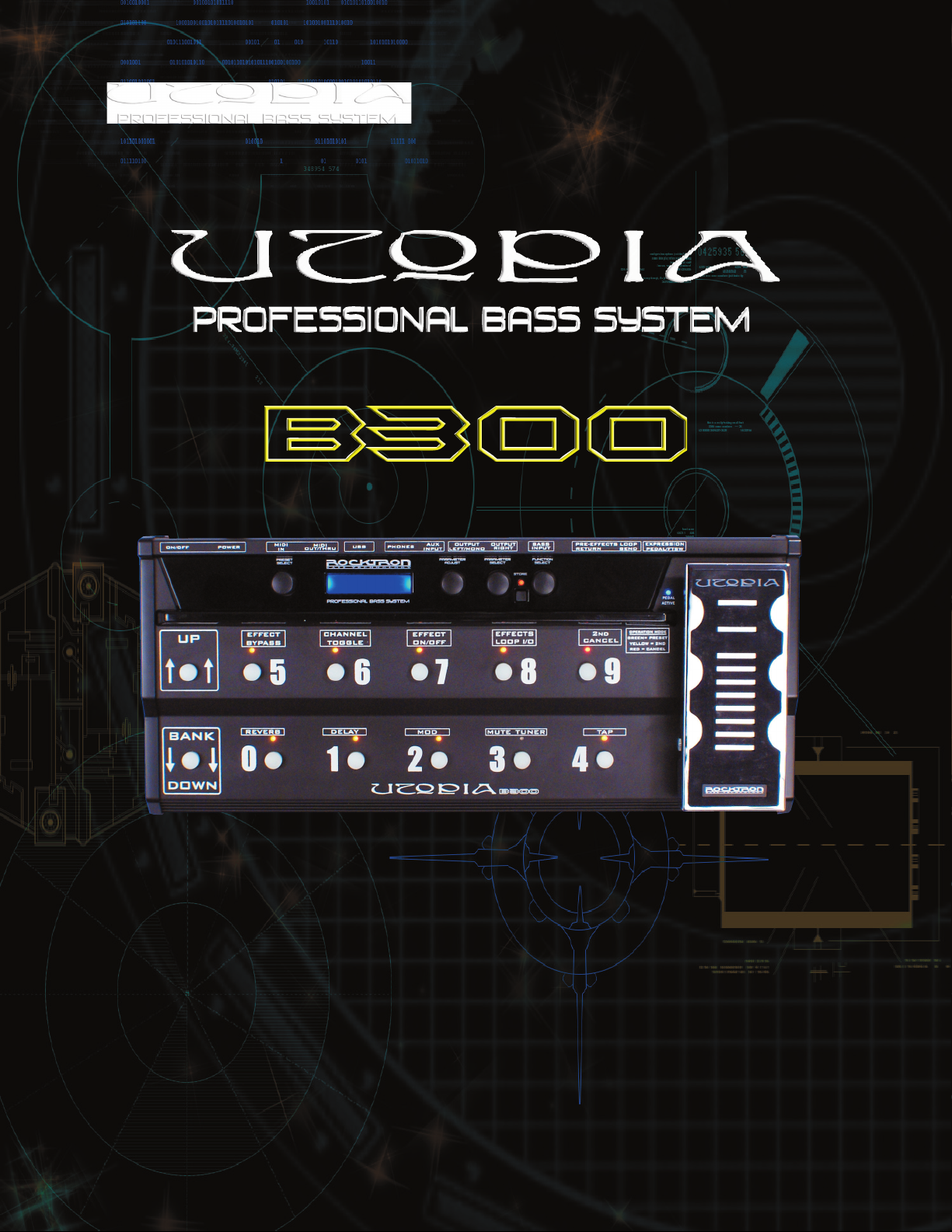
MANUAL
May be covered by one or more of the following: U.S. Patents
#4538297, 4647876, 4696044, 4745309, 4881047, 4893099, 5124657, 5263091,
5268527, 5319713, 5333201, 5402498 and 5493617.
Other patents pending. Foreign patents pending.
1
Page 2

Your UTOPIA B300 has been designed to comply with the following Standards and Directives as
set forth by the European Union:
Council Directive(s): 89/336/EEC, 73/23/EEC, 76/769/EC, 1994/62/EC, 2000/
53/EC, 2002/95/EC
Standard(s): EN55022, EN50082-1, EN60065
This means that this product has been designed to meet stringent guidelines on how much RF
energy it can emit, and that it should be immune from other sources of interference when properly
used. Improper use of this equipment could result in increased RF emissions, which may or may
not interfere with other electronic products.
To insure against this possibility, always use good shielded cables for all audio input and output
connections. This will help insure compliance with the Directive(s).
Copyright © 2007 GHS Corporation.
All rights reserved.
2
Page 3

CONTENTS
1. Introduction 4
2. Quick Reference 6
3. UTOPIA B300 Top and Back Panels 8
4. Connections 14
5. Operating Format 23
6. UTOPIA B300 Functions and Parameter Description 24
� GLOBAL Function 25
� MIXER Function 26
� PREAMP Function 26
� HUSH® Function 28
� SPEAKER Exciter Function 29
� COMPRESSOR Function 30
� EFFECTS LOOP Function 31
� WAH-WAH Function 32
� PHASER Function 33
� MODULATION EFX Function 34
� CHORUS Function 35
� FLANGER Function 37
� TREMOLO Function 38
� PITCH SHIFT Function 39
� PITCH SHIFT INTERVALS 40
� DELAY Function 41
� TAP QUANTIZING Function 43
� REVERB Function 44
7. UTOPIA B300 Block Diagrams 45
� Chorus, Flanger and Pitch Shift 45
� Tremolo 46
� Function and Parameter range list 47
8. Operating the UTOPIA B300 50
� Display Description 50
� Selecting a preset 51
� Preset Banks 52
� Changing preset parameters: 53
� Storing changed preset parameters: 54
� Operation Mode 56
� Selecting a Modulation Effect 57
� MUTE/TUNER Function 58
� USB Connection 60
� MIDI IN 60
� MIDI OUT/THRU 60
� MIDI Channels - MIDI Receive 61
� MIDI Channels - MIDI Transmit 62
� Program Changes 63
� MIDI DUMP/LOAD Functions 64
� Pedal Controllers 66
� Pedal Status 70
� Footswitch Mapping 73
� Factory Restore 75
� Title Edit 77
� Selecting a Power on Preset 79
9. Specifications 80
10. UTOPIA B300 Preset Listing 81
3
Page 4

1. Introduction
UTOPIA B300 PROVIDES PROFESSIONAL SOUND FOR BASS
Rocktron’s Utopia B300 Professional Bass System provides an arsenal of tone and effects processing.
The B300 is packed with plenty of great sounds ready to transform any Bass amplifier into a Powerhouse of Rock. Simply put the B300 between you and your amp and let your inspiration flow! Rocktron
stands alone with amazing tone generation and effects in the B300 - everything you need to create your
own signature sound and define a new generation of playing. Play in Utopia where the future is amazing.
� Great Tone!
� 128 Fully programmable presets
� Chorus, Reverb, Delay, Pitch Shift, Flanger, Phaser and Tremolo
� Easy to program user controls
� Up/Down preset Bank by 10 with instant recall buttons.
� 2nd mode with 10 instant access controller switches.
� Tap delay note quantization 1/16 , 1/8, triplet, ¼, ½ and whole.
� Illuminated noiseless footswitches
� Glow in the dark markings on pedal board
� Rocktron’s state-of-the-art HUSH noise reduction
� On board pro-grade expression pedal with integrated footswitch and LED.
� Upgradable core processing hardware design [ DSP CARD and CODEC CARD ]
� Motorola [Freescale] DSP engine with AKM converters
� Programmable Pre-processing analog effects loop
� Extra External Expression controller pedal port
� Easy to read 2 line cool blue LCD display
� USB audio recording and playback connectivity
� Rocktron’s state of the art Speaker Exciter for recording and live sound.
� MIDI in and MIDI out/thru
� Auxiliary CD/Mp3/iPOD in 1/8 jack
� Stereo headphone out
� Built-in tuner
� Full Bandwidth effects
� Rugged professional grade chassis and expression pedal made from metal
� Assignable Effect On/Off
� Power supply included
Motorola is a trademark of Motorola Corporation. HUSH is a registered trademark of GHS Corporation.
iPod is a trademark of Apple Inc.
4
Page 5

PRECAUTIONS
NOTE: IT IS VERY IMPORTANT THAT YOU READ THIS SECTION TO PROVIDE YEARS OF TROUBLE FREE USE. THIS UNIT REQUIRES CAREFUL HANDLING.
• All warnings on this equipment and in the operating instructions should be
adhered to and all operating instructions should be followed.
• Do not use this equipment near water. Care should be taken so that objects
do not fall and liquids are not spilled into the unit through any openings.
• The power cord/adapter should be unplugged from the outlet when left
unused for a long period of time.
• Do not block any ventilation openings (if applicable). Install in accor
-
dance with the manufacturer’s instructions.
• Do not install near any heat sources such as radiators, heat registers, stoves
or other apparatus (including amplifiers) that produce heat.
• Only used attachments/accessories specified by the manufacturer.
• Do not use this product with any case, stand, tripod, bracket or table that
is not specified by the manufacturer. Insure that the case, stand, tripod,
bracket etc. is properly adjusted and setup (follow all instructions). Extra
care and caution should be taken to avoid tip over and injury.
• Unplug this apparatus during lightning storms or when unused during long
periods of time.
Refer all service to qualified service personnel. Servicing is required when the apparatus has been
damaged in any way, such as power supply or plug is damaged, liquid has been spilled or objects have
fallen into the apparatus or if the apparatus has been exposed to rain or moisture, does not operate normally or has been dropped.
DO NOT ATTEMPT TO SERVICE THIS EQUIPMENT. THIS EQUIPMENT
SHOULD BE SERVICED BY QUALIFIED PERSONNEL ONLY. DO NOT MAKE
ANY INTERNAL ADJUSTMENTS OR ADDITIONS TO THIS EQUIPMENT AT
ANY TIME. DO NOT TAMPER WITH INTERNAL ELECTRONIC COMPONENTS
AT ANY TIME. FAILURE TO FOLLOW THESE INSTRUCTIONS MAY VOID THE
WARRANTY OF THIS EQUIPMENT, AS WELL AS CAUSING SHOCK HAZARD.
OPERATING TEMPERATURE
Do not expose this unit to excessive heat. This unit is designed to operate between
32° F and 104° F (0° C and 40° C). This unit may not function properly under extreme
temperatures.
5
Page 6
2. Quick Reference
6
Page 7

2. Quick Reference....continued...
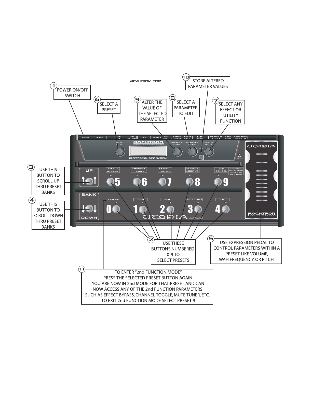
STEP 1 Turn ON the UTOPIA B300.
STEP 2 Select your desired preset by pressing any button 0-9 to select presets. You
may also do this by following STEP 6. NOTE - the B300 starts with preset
number 1, preset 0 does not exist.
STEP 3 Scroll through the different preset banks by pressing the UP button (Bank by
10). You may also reach your desired preset by following STEP 6.
STEP 4 Scroll through the different preset banks by pressing the DOWN button (Bank
by 10). You may also reach your desired preset by following STEP 6.
STEP 5 Use the built-in expression pedal to change the parameter(s) in real time that
are assigned to the pedal controllers function.
STEP 6 You may also select a preset by turning the PRESET SELECT knob.
STEP 7 Turn the FUNCTION SELECT knob to the desired effect or utility function.
STEP 8 Turn the PARAMETER SELECT knob to the parameter you wish to alter under
the selected effect or utility function.
STEP 9 Use the PARAMETER ADJUST knob to modify a parameter value.
STEP 10
After editing any function parameter press the STORE button to start the
storing procedure. The display will toggle and flash "STORE AT PRESET."
If you wish to save the altered preset in the current preset location, press the
STORE button a second time. If you wish to store the altered preset in a differ-
ent preset location, turn the PRESET control to the desired preset number, then
press STORE a second time. Anytime you wish to cancel the store process just
turn the PARAMETER ADJUST one click.
STEP 11 To
enter the "2ND Function" mode, press the selected preset switch a second
time, this will turn the multi-colored LED(s) Yellow and turn on a RED LED
on button "9" (2nd Cancel). Any Function that has been assigned to that preset
will turn on the LED in Yellow. You can now turn On/Off functions within that
preset. Use the switched marked 2nd Cancel button "9" with the Red LED to
exit the 2nd Function mode.
7
Page 8
3. UTOPIA B300 Top and Back Panels
8
Page 9

3. UTOPIA B300 Top and Back Panels....continued.....
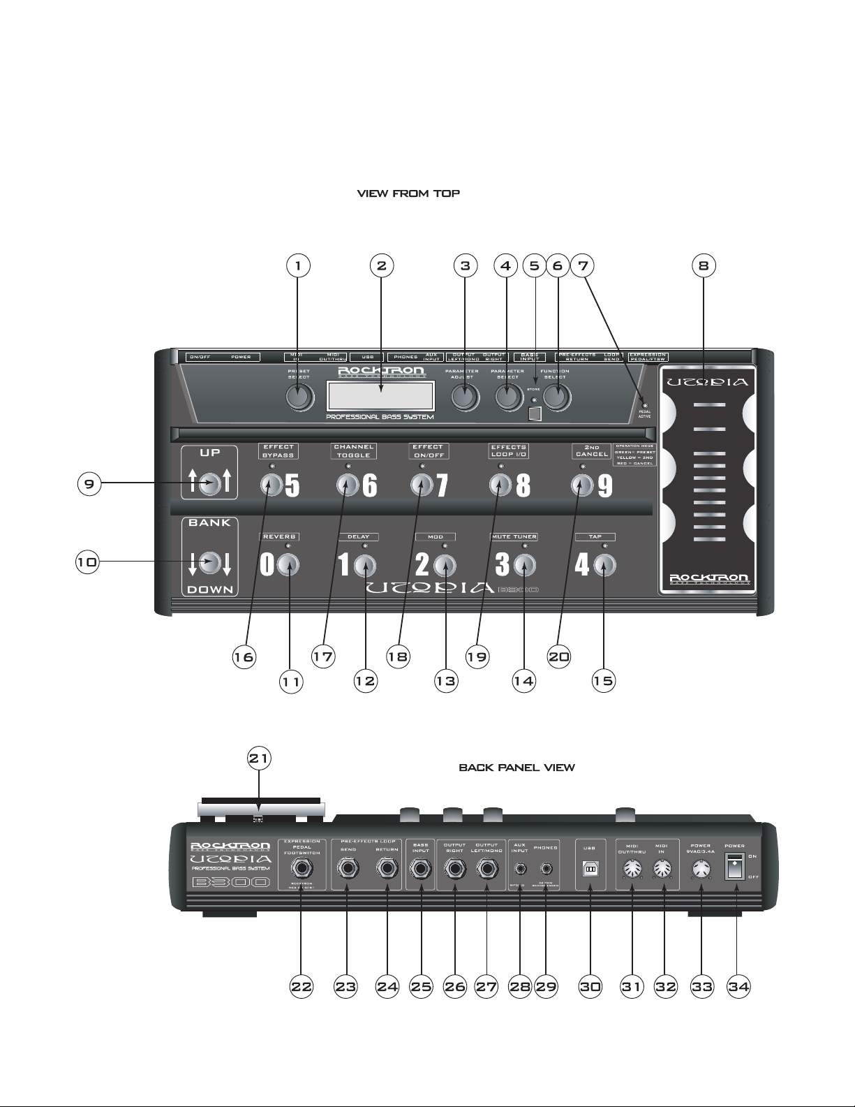
1 PRESET SELECT control
Turning this knob scrolls through the successive presets.
2 DISPLAY panel
The DISPLAY shows the preset names, functions and parameters that are selected.
3 PARAMETER ADJUST control
4 PARAMETER SELECT control
When adjusting parameter values, turning this knob will scroll through the available parameters
5 STORE button and STORE LED
This button is used to store values into the B300's memory when altered. See "Storing
This knob is used to adjust a displayed parameter value. Note that this knob is also used as a
controller knob and is set to MASTER VOLUME from the factory. So you can use this knob to
adjust the overall volume of the B300. However, this knob also can be assigned to other controller parameters (see Pedal Controllers section in this manual for more details).
under the current function heading. In the "Title Edit" function, this knob will scroll through the
character locations to be edited.
Changed Preset Parameters" for more information on this procedure.
6 FUNCTION SELECT control
This knob allows access to each function of the UTOPIA B300 depending on which configura
-
tion is currently recalled.
7 PEDAL ACTIVE LED
This LED will light when the built-in expression pedal is active or on.
8 EXPRESSION PEDAL
The built-in expression pedal will change parameter(s) that have been assigned to the pedal in the
Pedal Controllers function. Use the pedal to increase or decrease volume levels, or for a pitch
shifting wammy effect, or to bring in reverbs and delays. There are many uses for this pedal.
Please see the Pedal Controllers section of this manual for information how to program the expression pedal for many cool effects.
9 UP button
This button allows you to scroll UP through the preset banks. Each B300 preset bank has 10
presets in it (note there is no Zero (0) preset or Preset 129)
Bank 00 - Presets 1-9
Bank 01 - Presets 10-19
Bank 02 - Presets 20-29
Bank 03- Presets 30-39
Bank 04 - Presets 40-49
Bank 05 - Presets 50-59
Bank 07- Presets 70-79
Bank 08 - Presets 80-89
Bank 09 - Presets 90-99
Bank 10 - Presets 100-109
Bank 11 - Presets 110-119
Bank 12 - Presets 120-128
Bank 06 - Presets 60-69
9
Page 10

3. UTOPIA B300 Top and Back Panels....continued.....
Press the UP button once to move one preset bank up or press and hold down the button to auto-
scroll UP. Note that once you have reached your desired preset, the preset name on the screen
will be flashing but NOT recalled. The original preset will still be active. Now select any preset
0-9 to recall or activate the desired preset.
10 DOWN button
11 PRESET button 0
This button allows you to select presets 10, 20, 30, 40, 50, 60, 70, 80, 90, 100, 110 and 120.
12 PRESET button 1
This button allows you to select presets 1, 11, 21, 31, 41, 51, 61, 71, 81, 91, 101, 111 and 121.
This button allows you to scroll DOWN through the preset banks and functions in the same manner as the UP button (point 9).
When you are in Bank 01 this button allows you to select preset 10. When you are in Bank 02
this button allows you to select preset 20 and so on. Note that there is no 0 (zero) preset. Pressing this button a second time allows you to enter into the 2nd Function mode for this preset. You
can then use this button to turn On/Off the REVERB on the preset selected.
When you are in Bank 00 this button allows you to select preset 1. When you are in Bank 01 this
button allows you to select preset 11 and so on. Pressing this button a second time allows you to
enter into the 2nd Function mode for this preset. You can then use this button to turn On/Off the
DELAY on the preset selected.
13 PRESET button 2
This button allows you to select presets 2, 12, 22, 32, 42, 52, 62, 72, 82, 92, 102, 112 and 122.
When you are in Bank 00 this button allows you to select preset 2. When you are in Bank 01 this
button allows you to select preset 12 and so on. Pressing this button a second time allows you to
enter into the 2nd Function mode for this preset. You can then use this button to turn On/Off the
MOD (MODULATION EFFECT) on the preset selected.
14 PRESET button 3
This button allows you to select presets 3, 13, 23, 33, 43, 53, 63, 73, 83, 93, 103, 113 and 123.
When you are in Bank 00 this button allows you to select preset 3. When you are in Bank 01 this
button allows you to select preset 13 and so on. Pressing this button a second time allows you to
enter into the 2nd Function mode for this preset. You can then use this button to turn On/Off the
MUTE on the preset selected. Pressing this button a third time allows you to enter into TUNER
mode and you can tune your bass with the built-in tuner. To exit the TUNER mode you must
press button 3 again.
15 PRESET button 4
This button allows you to select presets 4, 14, 24, 34, 44, 54, 64, 74, 84, 94, 104, 114 and 124.
When you are in Bank 00 this button allows you to select preset 4. When you are in Bank 01 this
button allows you to select preset 14 and so on. Pressing this button a second time allows you to
enter into the 2nd Function mode for this preset. You can then use this button to activate the TAP
function and set the DELAY Rate by tapping the button at the desired rate.
10
Page 11

3. UTOPIA B300 Top and Back Panels....continued.....
16 PRESET button 5
This button allows you to select presets 5, 15, 25, 35, 45, 55, 65, 75, 85, 95, 105, 115 and 125.
When you are in Bank 00 this button allows you to select preset 5. When you are in Bank 01 this
button allows you to select preset 15 and so on. Pressing this button a second time allows you to
enter into the 2nd Function mode for this preset. You can then use this button to turn On/Off the
EFFECT BYPASS on the preset selected.
17 PRESET button 6
This button allows you to select presets 6, 16, 26, 36, 46, 56, 66, 76, 86, 96, 106, 116 and 126.
When you are in Bank 00 this button allows you to select preset 6. When you are in Bank 01 this
button allows you to select preset 16 and so on. Pressing this button a second time allows you to
enter into the 2nd Function mode for this preset. You can then use this button to turn On/Off the
CHANNEL TOGGLE on the preset selected.
18 PRESET button 7
This button allows you to select presets 7, 17, 27, 37, 47, 57, 67, 77, 87, 97, 107, 117 and 127.
When you are in Bank 00 this button allows you to select preset 7. When you are in Bank 01 this
button allows you to select preset 17 and so on. Pressing this button a second time allows you to
enter into the 2nd Function mode for this preset. You can then use this button to turn On/Off the
a pre-assigned EFFECT on the preset selected.
19 PRESET button 8
This button allows you to select presets 8, 18, 28, 38, 48, 58, 68, 78, 88, 98, 108, 118 and 128.
When you are in Bank 00 this button allows you to select preset 8. When you are in Bank 01 this
button allows you to select preset 18 and so on. Pressing this button a second time allows you
to enter into the 2nd Function mode for this preset. You can then use this button to activate the
EFFECTS LOOP I/O (In/Out)
20 PRESET button 9
This button allows you to select presets 9, 19, 29, 39, 49, 59, 69, 79, 89, 99, 109, and 119 (note
there is no preset 129). When you are in Bank 00 this button allows you to select preset 9.
When you are in Bank 01 this button allows you to select preset 19 and so on. Pressing this button a second time allows you to enter into the 2nd Function mode for this preset. You can then
must use this button to exit the 2nd Function mode.
21 EXPRESSION PEDAL switch
To activate the Expression pedal, apply pressure to the toe of the expression pedal until this
switch is activated. You will know the pedal is active as you should be able to feel the switch
activate, but if not, the PEDAL ACTIVE LED will light when the switch is turned ON.
22 EXPRESSION PEDAL Jack
You can add an additional expression pedal or footswitch to the B300 using this jack and a RTS
¼ jack [stereo] cable. You can assign any parameter in the B300 to be adjusted by this pedal. We
recommend the following (sold separately) Rocktron Utopia Expression pedal, Rocktron HEX
Pedal or Rocktron VSF1 Footswitch.
11
Page 12

3. UTOPIA B300 Top and Back Panels....continued.....
23 PRE-EFFECTS (mono) LOOP SEND jack
Use this jack to send the signal from the B300 to the input of an outboard effect such as a
Rocktron Xpression or your favorite stomp box.
24 PRE-EFFECTS (mono) LOOP RETURN jack
Use this jack to receive the signal back from the output of the outboard effect or stomp box.
25 INPUT jack
26 OUTPUT RIGHT jack
This 1/4" jack provides the right output of the UTOPIA B300 for use in stereo situations, such as
27 OUTPUT LEFT/MONO jack
This 1/4" jack provides the left output of the UTOPIA B300. This output is a MONO output and
This standard, mono 1/4" jack is used to provide input to the unit.
direct recording, plugging into a PA system, two Bass amplifiers, etc.
should be used in mono situations, such as plugging into the front of an amplifier. For stereo
situations you must also use the OUTPUT RIGHT Jack.
28 AUX INPUT Jack
This 1/8" stereo jack provides an auxiliary input allowing you to plug a MP3 Player, CD Player,
etc. so that you can jam along with your favorite tunes.
29 PHONES jack
This 1/8” stereo jack provides a stereo output allowing you to practice in private. Note that you
need to activate the “STEREO” parameter in the GLOBAL Function in order to have a stereo
sound. Additionally, it is recommended that you set the Speaker Exciter in the GLOBAL Function to “LOCK BOTH” as well. Note, this setting will be used until you turn OFF the UTOPIA
B300. The SPEAKER Exciter setting used in each preset may be modified per preset while in
this mode. See page 25 for more information on the GLOBAL Function. Note: Make sure if you
edit a preset and plan to store it to turn the SPEAKER EXCITER off if you do not desire to store
its current status. All global parameters will be stored during the preset storing process.
30 USB
jack
This standard USB jack allows you to connect to a computer for direct recording and
playback.
31 MIDI IN
jack
This *7-pin DIN connector receives MIDI information from the device which is transmit-
ting the MIDI commands for the B300 to execute.
12
32 M
IDI OUT/THRU jack
This *7-pin DIN connector passes on the MIDI information that is received at the MIDI IN
jack to other MlDI-compatible devices via a MIDI cable. It also outputs MIDI data when
performing a memory dump.
*Note a standard 5-pin MIDI cable may be used.
Page 13

3. UTOPIA B300 Top and Back Panels....continued.....
33 POWER jack
This 4-pin DIN connector accepts power from the 9V/AC adaptor supplied with the B300.
34 POWER Switch
Use this switch to turn the UTOPIA B300 On and Off.
13
Page 14
4. Connections
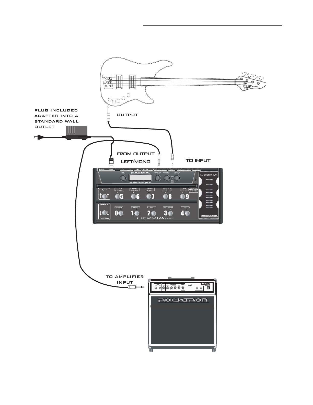
Standard Connection with a Bass Amplifier
14
Page 15
4. Connections....continued.....
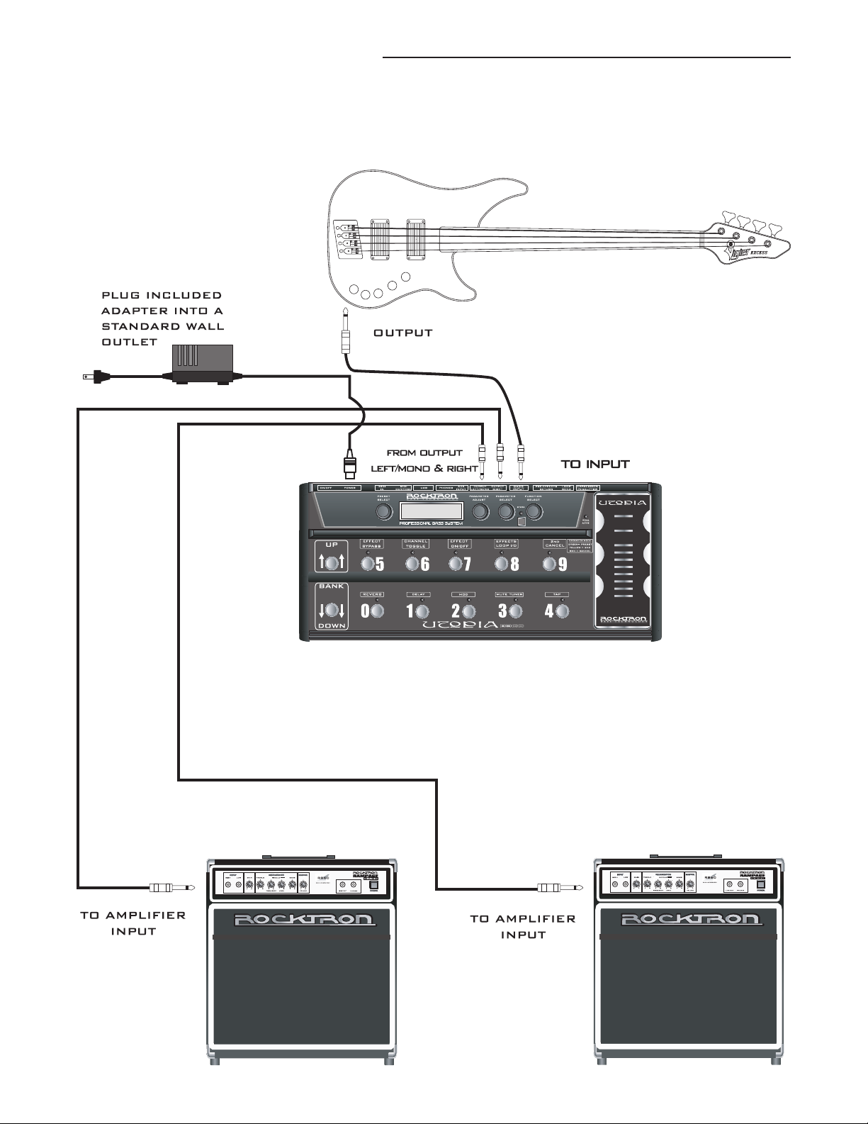
Connection in Stereo to Two Bass Amplifiers.
15
Page 16
4. Connections....continued.....
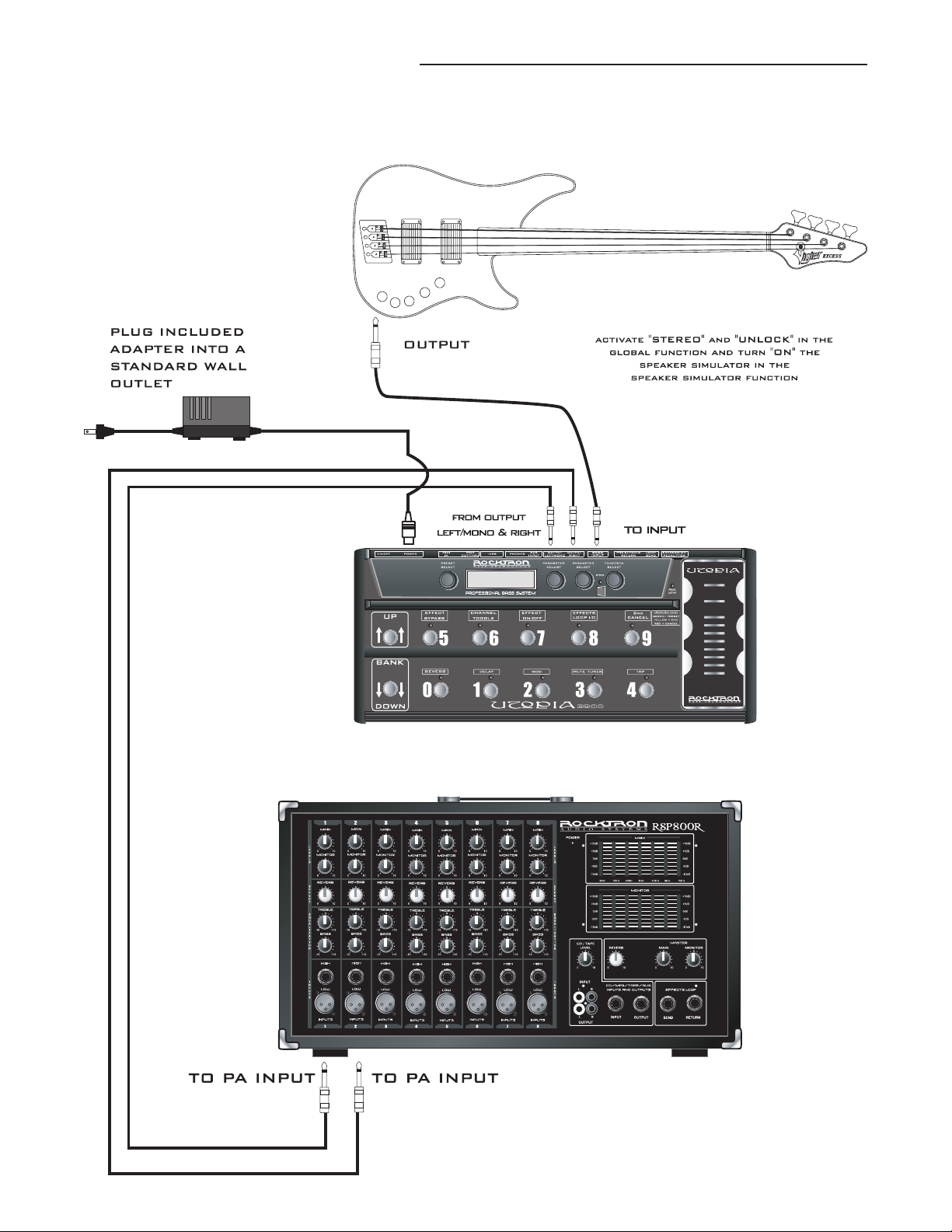
Connection to a PA System
16
Page 17
4. Connections....continued.....
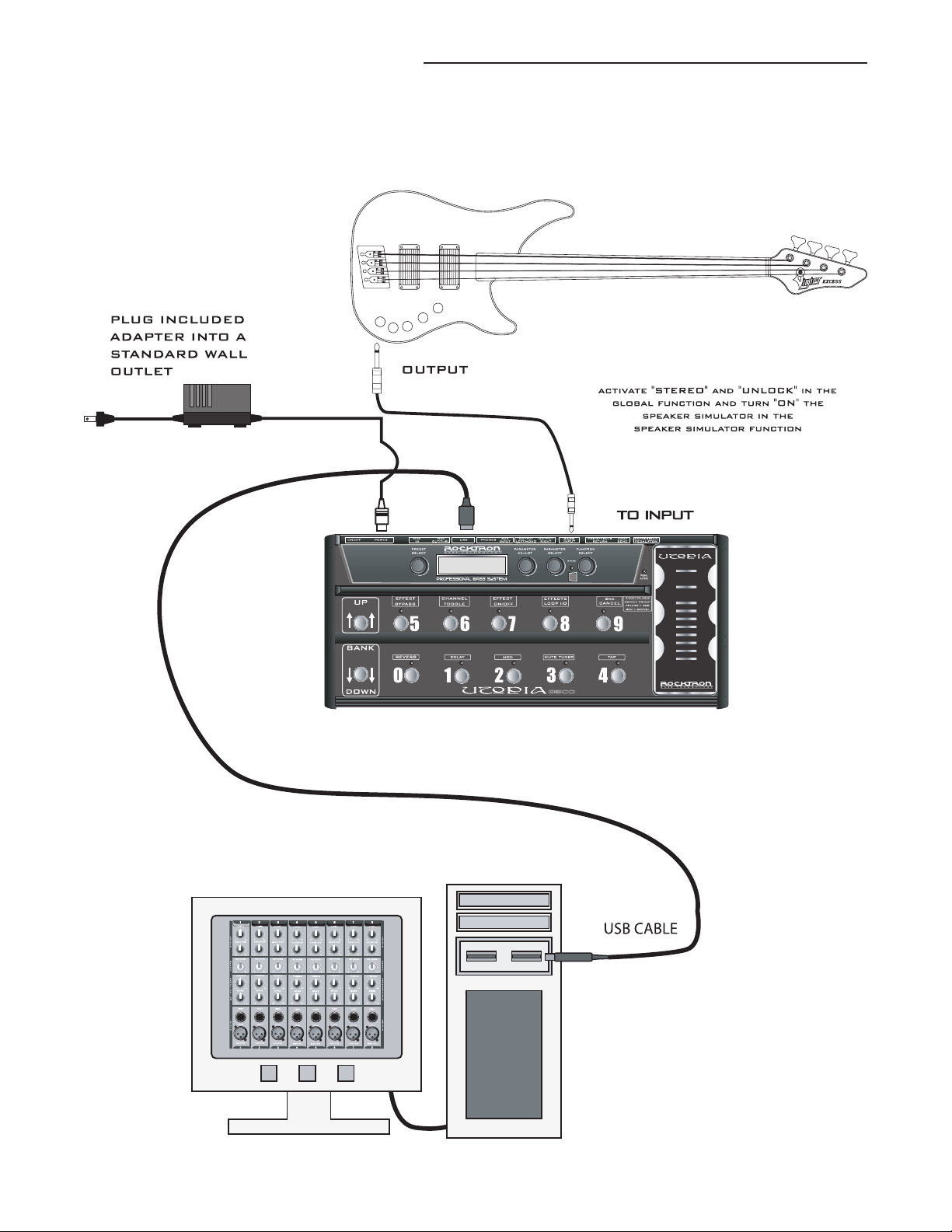
Connection to a Computer
17
Page 18
4. Connections....continued.....
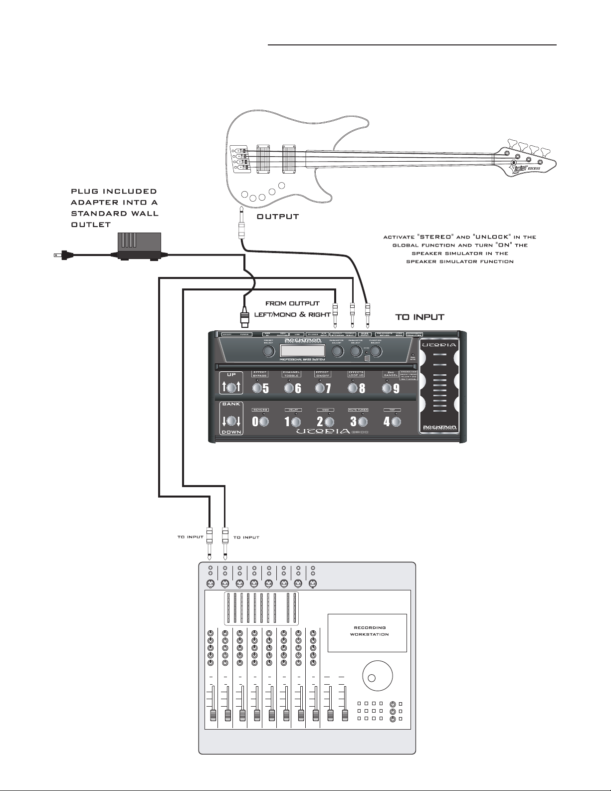
Connection to a Recording Workstation
18
Page 19
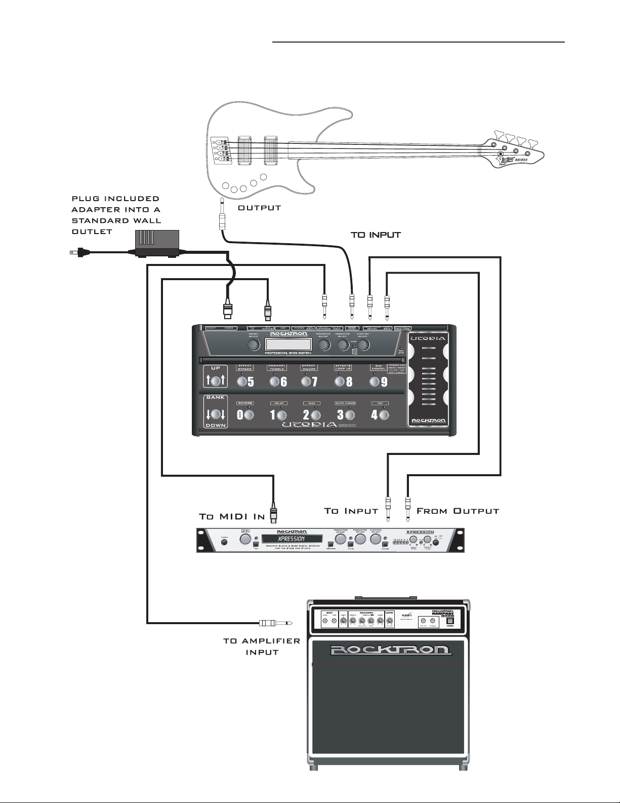
4. Connections....continued.....
Connection Using Effects Loop and MIDI
19
Page 20
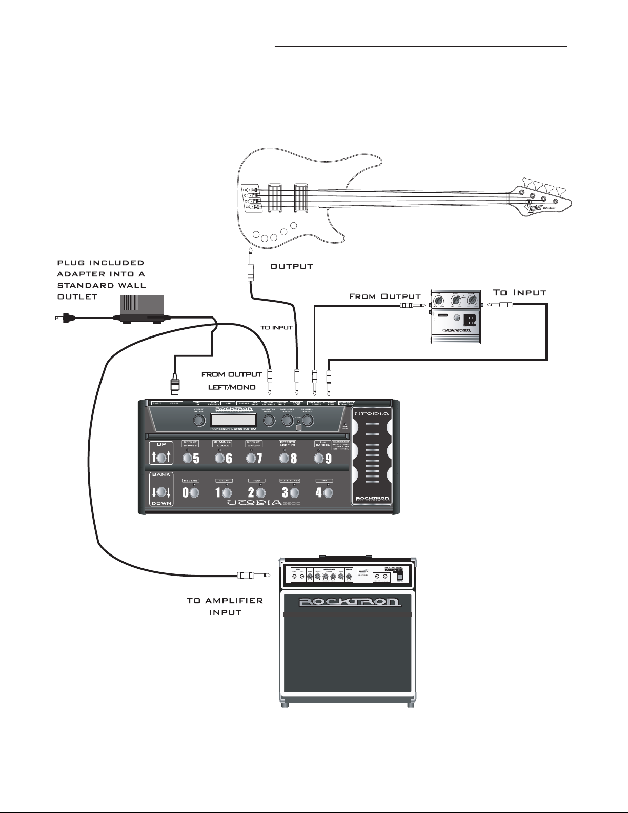
4. Connections....continued.....
Connection Using Effects Loop to a Stompbox
20
Page 21
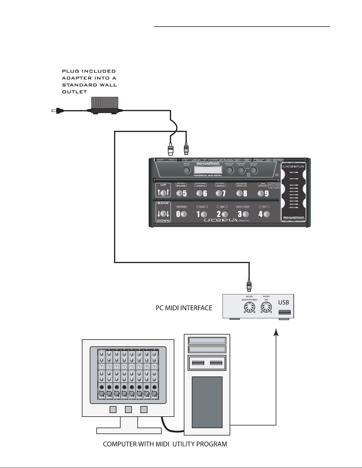
4. Connections....continued.....
Connection for MIDI IN from a Computer with
MIDI Utility Program
21
Page 22
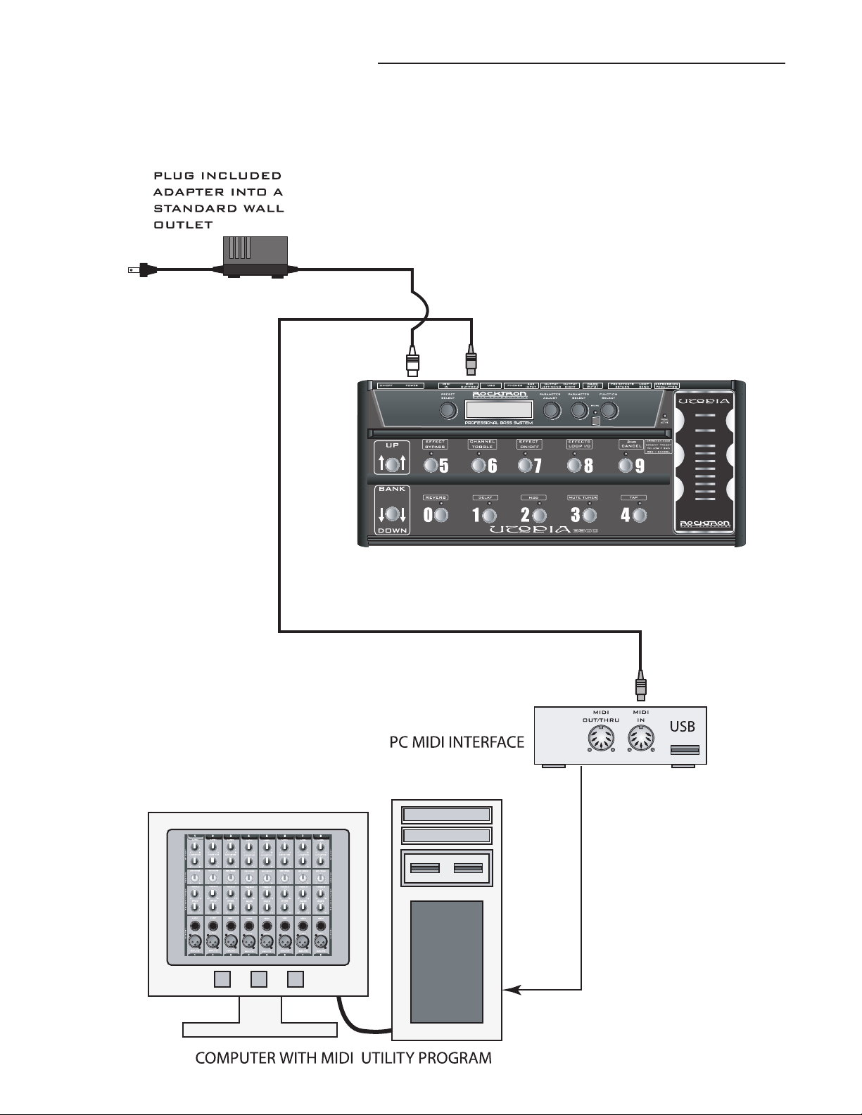
4. Connections....continued.....
Connection for MIDI OUT to Computer with MIDI
Utility Program
22
Page 23

5. Operating Format
The B300 provides 128 stored sounds called presets. Any of the 128 presets can be
called up at any time via the PRESET knob, or by using the BANK UP/DOWN buttons
and PRESET switches.
Each preset has the following effects available at all times:
Effects Loop (use to control on/off status of any outboard gear connected to the B300)
Compressor
Wah Wah
Phaser
Preamp
HUSH
Speaker Exciter
One Modulation Effect ( Chorus, Flanger, Tremolo or Pitch Shift)
Delay
Reverb
23
Page 24
6. UTOPIA B300 Functions and Parameter Descriptions
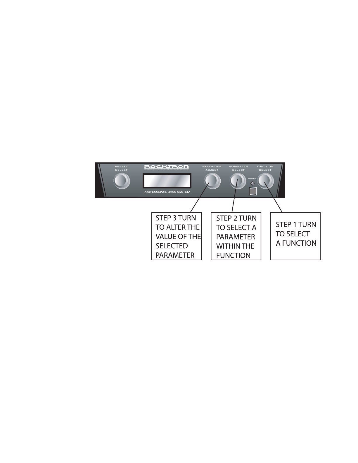
Each UTOPIA B300 preset is divided up into individual blocks called functions (such as "Mixer", "Reverb", etc.). Within each function of each configuration is a set of controls which allow you to manipulate various aspects of that
function. These controls are called parameters. It is the setting of each of the
parameters which determines the overall sound of each preset.
The UTOPIA B300 is set up to allow you to first access each function (via the
FUNCTION SELECT knob), then the parameter list for each function (via the
PARAMETER SELECT knob) and finally the adjustable value for each parameter
(via the PARAMETER ADJUST knob).
24
The functions available for each preset are dependent upon which effect is
currently recalled. The remainder of this section will describe each of the effectbased functions and the associated adjustable parameters they provide.
The remaining functions are utility-based, and are described in the section
titled "Operating the UTOPIA B300".
Page 25

6. GLOBAL Function
The first function displayed after turning the FUNCTION SELECT knob is the Global function. The
parameters provided in this function affect all presets (i.e. the settings stored for these parameters are the
same for all presets).
The PARAMETER SELECT knob will allow you to access these Global parameters:
OUTPUT
EXCITER
HUSH OFFSET
MASTER VOLUME
The OUTPUT parameter determines whether the output of the UTOPIA B300 is
a stereo (left and right) signal or two mono signals.
This Speaker EXCITERr parameter under the Global function allows you to
globally (all presets) set the Speaker Exciter into the following modes:
UNLOCK - Bypasses the Speaker Exciter on all presets leaving the outputs full
range.
LOCKOFF - If you have the Speaker Exciter "ON" in the Speaker Exciter Function the Speaker Exciter will turn on when that preset is selected.
LOCK L (LEFT OUTPUT) - Locks the Speaker Exciter "ON" in the LEFT
OUTPUT and leaves the Right OUTPUT full range. Allows you to use the left
output for direct recording or direct to a PA and the right output to your amp at
the same time to perform live.
LOCK B (BOTH OUTPUTS) - Locks the Speaker Exciter "ON" in both Left and
Right Outputs. This is the ideal setting to use when using headphones.
The HUSH OFFSET parameter allows you to globally (all presets) adjust the
HUSH® Expander Threshold. This means that if this parameter is altered from
0(dB) to +3(dB), the Expander Threshold will be 3dB higher for all presets. This
feature can be useful when switching from a quiet bass with passive electronics
to a noisy bass with active electronics, as the active bass would require a higher
Threshold level in all presets.
The *MASTER VOLUME has a range from -40dBu to +6dBu. This control
adjusts the overall volume of the output and is extremely useful in adjusting the
volume in headphones.
*Note: When the preset title is being displayed the PARAMETER ADJUST con
trol will provide instant access to modify the MASTER VOLUME anytime.
NOTE: If you would like to save any changes made to the GLOBAL PARAMETERS you must STORE
them at this time, before leaving the GLOBAL FUNCTION.
-
25
Page 26

6. MIXER Function
The next function displayed after turning the FUNCTION SELECT knob clockwise is the Mixer function.
The Mixer function parameters are included in all presets -- regardless of which configuration is currently recalled
-- although the parameter values stored in this function are only for the currently recalled preset.
This digital mixer allows you to control most signal levels pertaining to each preset's configuration and stores
these levels for each preset.
The PARAMETER SELECT knob will allow you to access these Mixer parameters:
VOLUME
LEFT OUT LVL
RIGHT OUT LVL
MIX DIR/EFF
DIR PAN
DELAY LVL
REVERB LVL
The VOLUME parameter determines the overall signal level of the current preset.
The LEFT OUT LEVEL parameter allows you alter the level of the left channel output
of the current preset independent of the right channel.
The RIGHT OUT LEVEL parameter allows you alter the level of the right channel out
put of the current preset independent of the left channel.
The DIR/EFF MIX parameter is used to define the ratio of direct signal level to effect
(Chorus, Flange, Pitch Shift) signal level.
The DIRECT PAN parameter allows you to pan the direct signal to the left or right.
The DELAY LEVEL parameter determines the overall level of the delayed signal at the
output relative to the direct signal and other effect signals. This parameter can also be
accessed from the Delay function parameter list.
The REVERB LEVEL parameter determines the level of the reverb signal at the output
relative to the direct signal and other effect signals. This parameter can also be accessed
from the Reverb function parameter list.
-
26
6. PREAMP Function
The PREAMP function is accessible in all configurations. The preamp stage offers 4 channel choices ranging
from clean to high gain for maximum sustain and distortion.
The PARAMETER SELECT knob will allow you to access these PREAMP parameters:
CHANNEL
GAIN
VARIAC ADJUST
The CHANNEL parameter chooses one of the four (4) PREAMP types: DEEP, NORM,
BRITE & DIST. DEEP, NORM and BRITE are different clean preamp tones and DIST
is a distortion preamp.
The GAIN parameter determines the gain value in the distortion stage.
The VARIAC ADJUST parameter adjusts the level at which the preamp stage in the
UTOPIA B300 begins to distort. A Variac is a voltage attenuating device that plugs into
an AC wall outlet and adjusts the voltage level to any device which is plugged into it.
For years, many bassists have plugged their amplifier heads into a Variac and reduced
the voltage coming into the amplifier from the AC wall outlet. This allows the ampli
fier tubes to reach saturation at a lower input level and increases the gain produced. The
VARIAC ADJUST parameter operates in a similar manner as a conventional Variac -where lowering the parameter value lowers the level at which saturation will take place.
-
Page 27

6. PREAMP Function continued.....
BASS
MID
TREBLE
PRESENCE
BRIGHT
SCOOP
MASTER
The BASS parameter adjusts the amount of low frequency information at the
output of each preset.
The MID parameter adjusts the amount of mid frequency information at the output of each preset.
The TREBLE parameter adjusts the amount of high frequency information at the
output of each preset.
The PRESENCE parameter also adjusts the amount of high frequency information at the output of each preset.
The BRIGHT parameter is displayed only when DEEP, NORM or BRITE pre
amps are active. The options you have are IN or OUT.
The SCOOP parameter is displayed only when DIST (the distortion peramp) is
active, and provides a fixed scoop of the mid frequencies.
The MASTER parameter determines the overall signal level coming out of the
preamp section.
-
SYMMETRY
POLARITY
DX-FILTER
MIX
DIR LPF
The SYMMETRY parameter (only available when the DIST preamp is selected)
adjusts the symmetry of the wave form. This may be adjusted from -28dB to
+6dB. 0dB is symmetrical. This may be used to approximate a tube bias charac
teristic. Depending on the settings and polarity more even or odd harmonics may
be produced during the distortion process.
Tip: When using -28dB you will notice a sense of a clean tone mixed in with the
distortion. This is a direct result of the Asymmetrical waveform transformation
process. By using varying amounts of symmetry a “ Tube feel” may be realized.
The POLARITY parameter (only available when the DIST preamp is selected)
determines which half of the wave gets processed.
The DX-FILTER parameter (only available when the DIST preamp is selected)
filters off the "harsh" high-end content. The lower the number the more highend cut. Zero (0) is no change.
When DIST channel is being used the MIX parameter provides the ability to
blend the Distortion with the Direct input before post EQ and effects processing.
The DIRECT LOW PASS FILTER attenuates frequencies down to lower bass.
This is useful when wanting to add only lower bottom end clean ambience into
the distortion blend. This provides transparent injection of low end presence
without sounding like two channels being mixed together.
-
27
Page 28
6. HUSH® Function
The HUSH® function is accessible in all presets - regardless of the configuration currently recalled.
HUSH is a patented single-ended noise reduction system. The HUSH system contained in the
UTOPIA B300, though modeled after the latest analog HUSH design, is a fully digital implementation
achieved through Digital Signal Processing (DSP).
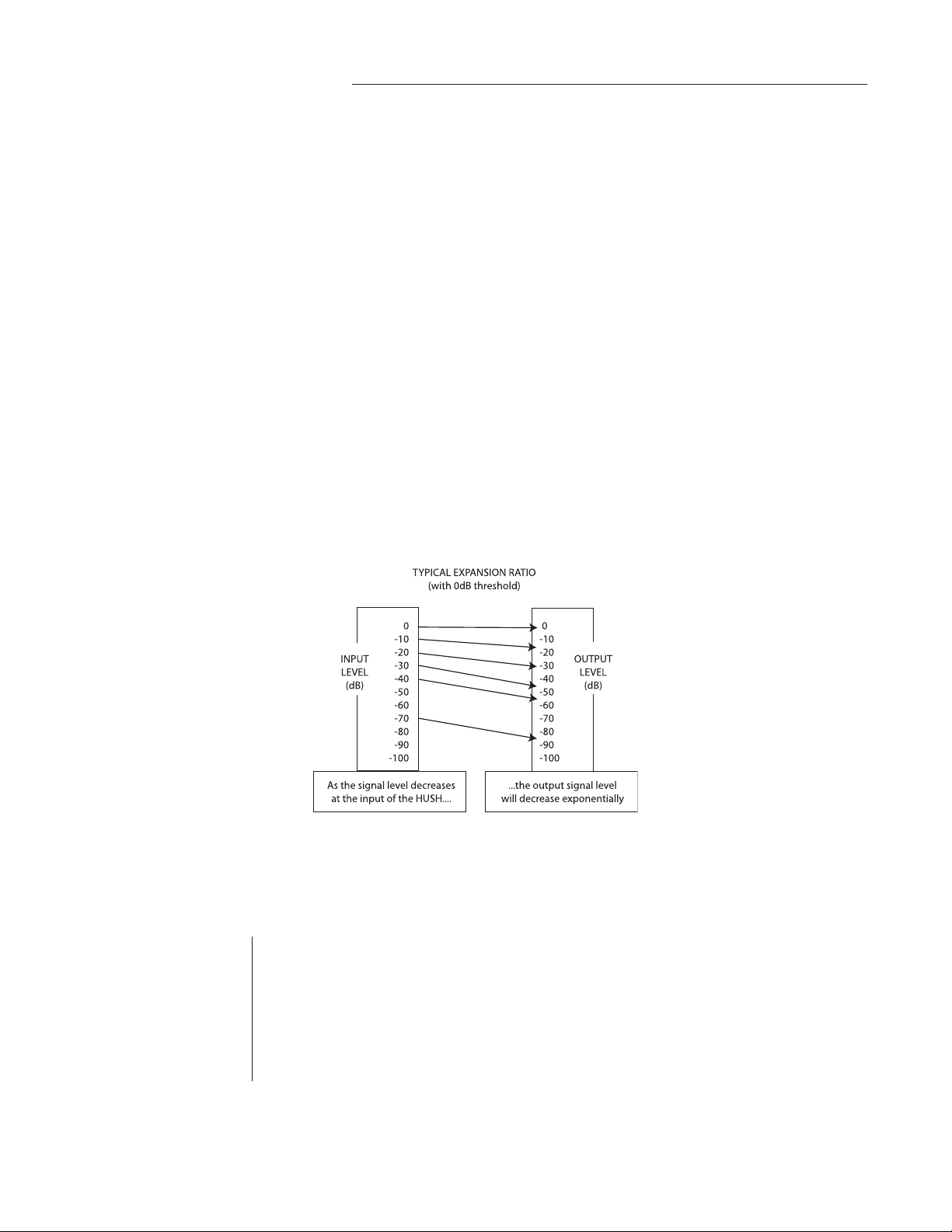
The low level expander of the HUSH system operates like an electronic volume control. The analog
version of the HUSH utilizes a voltage-controlled amplifier (VCA) circuit which can control the gain
between the input and the output from unity to 30, 40 or even 50(dB) of gain reduction. When the input
signal is above the user preset threshold point, the VCA circuit remains at unity gain. (This means that
the amplitude of the output signal will be equal to that of the input signal.) As the input signal level
drops below the user preset threshold point, downward expansion begins. At this point the expander acts
like an electronic volume control and gradually begins to decrease the output signal level relative to the
input signal level. As the input signal drops further below the threshold point, downward expansion increases. A drop in the input level by 20(dB) would cause the output level to drop approximately 40(dB)
(i.e., 20(dB) of gain reduction). In the absence of any input signal, the expander will reduce the gain so
that the noise floor becomes inaudible.
The HUSH circuit is located after the A/D converter in the signal chain to reduce any noise generated from the Bass and the A/D converter. This ensures a quiet input signal to the preamp section. Because the preamp section of the UTOPIA B300 is digital, it is virtually noise-free (even for the high-gain
28
channels). Therefore, a quiet input signal to the preamp will result in a quiet output signal.
The PARAMETER SELECT knob will allow you to access these Hush parameters:
HUSH I/O
EXP
THRESHOLD
The HUSH I/O parameter simply determines whether the HUSH® circuit is active for the current preset.
The EXP THRESHOLD (Expander Threshold) parameter determines the level at
which downward expansion begins. For example, if the EXP THRESHOLD was
set at -20(dB) and the input signal dropped below -20(dB), downward expansion
would begin.
Page 29

6. SPEAKER EXCITER Function
The SPEAKER Exciter function is included in all presets and provides a realistic approximation of
a miked speaker cabinet for applications involving connecting the UTOPIA B300 directly to a mixing
board, recording system or other full range system.
NOTE: The parameters provided in this function are operational
only when the SPKR XTR parameter under the GLOBAL
FUNCTION is stored UNLOCK, LOCK L or LOCK B.
The PARAMETER SELECT knob will allow you to access these SPEAKER Exciter parameters:
SPKR XTR
SPKR CURV
DEFINITION
SONIC BOOM
The SPEAKER Exciter parameter allows you to select whether the Speaker Exciter is on for BOTH outputs, on for only the LEFT output or OFF.
The SPEAKER CURV (curve) parameter determines the EQ Curve to be simu
lated. A, B, C, D and E are available. The range is from A having MORE lows
and E having more HIGHs.
The DEFINITION parameter accentuates the middle to upper highs for better
imaging of the sound delivered through any speaker whether it is live or used
when recording.
The SONIC BOOM parameter adds and extra kick in the pants of smooth ultra
lows which gives you a fatter sound. The higher the parameter value selected, the
more these characteristics will be apparent.
-
29
Page 30

6. COMPRESSOR Function
The COMPRESSOR function is available in all configurations. This function allows you to compress the signal prior to the distortion stage. Compression is often used to maintain an even level when
using clean tones, and also to increase sustain when using distorted tones.
The PARAMETER SELECT knob will allow you to access these COMPRESSOR parameters:
COMPRESSOR
COMP THRESH
COMP ATTACK
COMP RELEASE
The COMPRESSOR IN/OUT parameter determines whether the compressor is
active for the current preset.
The COMPRESSOR THRESHOLD parameter determines the input level (in dB)
at which compression will begin. Lower settings of this parameter will result in
more compression.
The COMPRESSOR ATTACK parameter determines the speed (in milliseconds)
in which the compressor will reach its maximum compression level after the
input signal has exceeded the threshold level (set by the COMPRESSOR
THRESHOLD parameter).
The COMPRESSOR RELEASE parameter determines the speed in which compression will cease after the input signal has dropped below the threshold level.
30
Page 31

6. EFFECTS LOOP Function
The EFFECTS LOOP function allows you to determine if the Effects Loop is ON or OFF for each
Preset.
The PARAMETER ADJUST knob will allow you to adjust this parameter:
EFX LOOP
The EFX LOOP control allows you to insert return audio from the device connected to the Effects Loop into the audio path before any processing. This means
you may connect your favorite Distortion pedal or effect and use them within any
preset and control their on/off status at anytime while using any preset. It should
be noted that the device inserted should be in its own active state [turned on].
31
Page 32

6. WAH-WAH Function
The WAH-WAH function is available only in configurations which display "WAH" in the configuration title.
The UTOPIA B300 has an internal wah-wah which allows for the built-in expression pedal to be
used as a wah-wah pedal when selected in the Pedal Controllers function. To do this, you will need to
activate this in the "PEDAL CONTROLLERS" function and assign the wah frequency sweep parameters
(See "PEDAL CONTROLLERS" for more information)
The PARAMETER SELECT knob will allow you to access these WAH-WAH parameters:
WAH-WAH
WAH FREQ
The WAH-WAH parameter determines whether the wah-wah is active for the
current preset. You can select IN to make the Wah active or OUT to turn it off.
The WAH FREQUENCY parameter allows you to manually sweep the frequency
range of the wah-wah via the PARAMETER ADJUST control. Selecting a frequency for this parameter and storing the WAH-WAH parameter IN allows you
to use the wah-wah as a fixed wah. You may also assign the wah to the built-in
expression. See section called "PEDAL CONTROLLERS" for more details.
32
Page 33

6. PHASER Function
The PHASER function is available only in configurations displaying "PHA" in the configuration
title.
Phase shifting involves splitting the input signal into two signals, then shifting the phase of different
frequencies of one signal and mixing it back with the original signal.
The PARAMETER SELECT knob will allow you to access these PHASER parameters:
PHASER
MIX DIR/EFF
DEPTH
P-RATE
RESONANCE
STAGES
The PHASER IN/OUT parameter determines whether the Phaser is active for the
current preset.
The DIR/EFF MIX parameter is used to define the ratio of direct signal level to
PHASER signal level.
The DEPTH parameter determines the modulation depth of the phase shift effect.
Higher parameter settings result in the sweep of the filtering effect occurring over
a wider frequency range.
The RATE parameter determines the speed at which the phase shifted signal is
modulated.
The RESONANCE parameter adds feedback to the Phaser so that it has a more
pronounced effect.
The STAGES parameter determines how many stages of phase shift are to be
active. A parameter setting of "4" produces a result similar to a vintage Phase 90,
while a setting of "6" emulates other phaser pedals.
33
Page 34

6. MODULATION EFX Function
The MODULATION EFX function allows you to select a MODULATION effect for each preset.
The PARAMETER ADJUST knob will allow you to select a Modulation Effect:
Available
Selections
Using the parameter adjust knob you can select one of the following MODULATION EFFECT:
CHORUS
FLANGER
TREMOLO
PITCH SHIFT
Once you have made a change in Modulation effect selection the B300 will auto
matically turn the effect on and load a preset state for you to start with or just use
as it is. You may then further edit the effect by turning the FUNCTION SELECT
knob one click to the right to access the FUNCTIONS of the selected Effect. See
following pages for details on the functions and parameters of each effect.
-
34
Page 35

6. CHORUS Function
The CHORUS function is available if you have selected it in the MODULATION EFX Function.
The Chorus effect in the UTOPIA B300 is produced by using two delayed signals (Voice 1 and Voice
2), detuning these delayed signals (slightly changing their pitch), then modulating the detune effect so
that the amount of pitch detune is constantly varying. Using different detune amounts, modulation rates,
modulation depths and pan settings for each delayed signal will produce a greater perceived spaciousness.
The PARAMETER SELECT knob will allow you to access these CHORUS parameters:
CHORUS
LEVEL 1
PAN 1
DEPTH 1
RATE 1
DELAY 1
The CHORUS parameter determines whether the Chorus is active or bypassed
for the current preset.
The LEVEL 1 parameter determines the volume of Voice 1 in relation to Voice 2.
The DIR/EFF MIX parameter in the Mixer function also determines the Chorus
level.
PAN 1 parameter allows you to pan Voice 1 to the left or right channel.
The DEPTH 1 parameter adjusts the amount of modulation of the Voice 1 signal.
A lower depth setting will produce a more subtle detune effect, while a higher
setting will produce a more extreme detuning of Voice 1.
The RATE 1 parameter determines the sweep speed (or the speed at which Voice
1 is modulated). Lower parameter settings will result in slower speeds, while
higher settings will result in faster speeds.
The DELAY 1 parameter allows you to select the minimum delay time (in mil
liseconds) for Voice 1. This delayed signal (along with Voice 2) is detuned and
modulated to produce the chorus effect. Using shorter delay times will result in a
tighter sounding chorused signal, while longer delay times will produce a larger
ambient effect.
-
35
Page 36

6. CHORUS Function Continued.....
LEVEL 2
PAN 2
DEPTH 2
RATE 2
DELAY2
The LEVEL 2 parameter determines the volume of Voice 2 in relation to Voice 1
PAN 2 parameter allows you to pan Voice 2 to the left or right channel.
The DEPTH 2 parameter adjusts the amount of modulation of the Voice 2 signal.
A lower depth setting will produce a more subtle detune effect, while a higher set
ting will produce a more extreme detuning of Voice 2.
The RATE 2 parameter determines the sweep speed (or the speed at which Voice
2 is modulated). Lower parameter settings will result in slower speeds, while
higher settings will result in faster speeds.
The DELAY 2 parameter allows you to select the minimum delay time (in mil
liseconds) for Voice 2. It is this delayed signal (along with Voice1) that is detuned
and modulated to produce the chorus effect. Using shorter delay times will result
in a tighter sounding chorused signal, while longer delay times will produce a
larger ambient effect.
-
-
36
Page 37

6. FLANGER Function
The FLANGER function is available if you have selected it in the MODULATION EFX Function.
Flanging involves splitting the input signal into at least two individual delayed signals (Voice 1 and
voice 2), then modulating these delayed signals so that, when summed back with the direct signal, phase
cancellations will occur at some frequencies while peaks in the response will occur at others.
The PARAMETER SELECT knob will allow you to access these FLANGER parameters:
FLANGER
LEVEL 1
PAN 1
DEPTH 1
RATE 1
LEVEL 2
PAN 2
The Flanger IN/OUT parameter determines whether the Flanger is active for the
current preset.
The LEVEL 1 parameter determines the volume of Voice 1 relative to Voice 2.
Tip: Keep the settings of these levels high and use the
DIR/EFF mix parameter in the Mixer function to control the overall amount of flanged signal.
The PAN 1 parameter allows you to pan Voice 1 to the left or right
channel.
The DEPTH 1 parameter adjusts the amount of modulation of Voice 1 . Lower
DEPTH settings produce more subtle effects, while higher settings will result in
a more drastic effect.
The RATE 1 parameter determines the speed at which Voice 1 is modulated.
The LEVEL 2 parameter determines the volume of Voice 2 relative to Voice 1.
The PAN 2 parameter allows you to pan Voice 2 to the left or right
channel.
DEPTH 2
RATE 2
REGEN
The DEPTH 2 parameter adjusts the amount of modulation of Voice 2. Lower
DEPTH settings produce more subtle effects, while higher settings will result in
a more drastic effect.
The RATE 2 parameter determines the speed at which Voice 2 is modulated.
The REGENERATION parameter determines how much of the delayed out
put signal is fed back into the input. More regeneration produces a more pronounced "jet airplane" type of effect.
-
37
Page 38

6. TREMOLO Function
The TREMOLO function is available if you have selected it in the MODULATION EFX Function.
The Tremolo effect continuously varies the volume of the signal.
The PARAMETER SELECT knob will allow you to access these TREMOLO parameters:
TREMOLO I/O
LOCATION
DEPTH
T-RATE
SHAPE
The TREMOLO IN/OUT parameter determines whether the Tremolo is active or
bypassed for the current preset.
The LOCATION parameter determines whether the Tremolo is located Pre-Re
verb or Post-Reverb. Most vintage amplifiers configured the Tremolo (or vibrato)
Post-Reverb.
The DEPTH parameter determines the amount of modulation for the Tremolo
signal. Lower DEPTH settings produce more subtle tremolo effects, while higher
settings will result in a more extreme tremolo effect.
The RATE parameter determines the speed at which the tremolo signal modu
lates (or increases and decreases in volume).
The SHAPE parameter determines the wave shape of the tremolo signal. Selecting a different wave shape produces a different tremolo effect.
-
-
38
Page 39

6. PITCH SHIFT Function
The PITCH SHIFT function is available if you have selected it in the MODULATION EFX Function.
Pitch Shifting is used to change the pitch of the input signal to produce a harmony note based on the
input signal. The harmony voice may be of any fixed interval—up to one octave above the input signal
to two octaves below—and is selected in 20-cent increments. Fine adjustment can be made in one cent
(1/ 100th semi tone) increments.
The PARAMETER SELECT knob will allow you to access these PITCH SHIFT parameters:
PITCH SHIFT
LEVEL
PAN
PITCH
The PITCH SHIFT IN/OUT parameter determines whether the Pitch Shifter is
active or bypassed for the current preset.
The LEVEL parameter determines the volume of the pitch shifted signal. The
DIR/EFF MIX parameter in the Mixer function also affects this volume.
The PAN parameter allows you to pan the shifted signal to the left or right chan
nel.
The PITCH parameter selects what harmony note the UTOPIA B300 will
produce based on the input note. The value displayed for this parameter
represents the number of cents that the signal will be shifted (adjustable in
20-cent increments). Each 100 cents (or five 20-cent steps) above or below "0"
represents the number of half-steps the shifted signal will be from the input
signal.
This parameter is adjustable from "-2400" to "+1200", where "-2400" = two
octaves below the input signal, "0" = unison and "+1200' = one octave above the
input signal. Refer to the table below to determine the cent value for each fixed
interval.
-
FINE
SPEED
The FINE parameter allows for adjustment in 1-cent steps for fine adjustment of
the harmony note.
The SPEED parameter determines the amount of time delay used in the shifting
process. SLOW results in the longest delay and the highest quality shifted signal (especially at larger amounts of pitch shift), FAST results in the least delay,
but the lowest quality shifted signal. This setting should only be used for slight
amounts of pitch shift.
39
Page 40

6. PITCH SHIFT INTERVALS
PARAMETER
VALUE
+1200
+1100
+1000
+900
+800
+700
+600
+500
+400
+300
+200
+100
0
-100
-200
-300
-400
-500
-600
-700
-800
-900
-1000
-1100
-1200
-1300
-1400
-1500
-1600
-1700
-1800
-1900
-2000
-2100
-2200
-2300
-2400
CORRESPONDING
INTERVAL
1 Octave
Major 7th
minor 7th
Major 6th
minor 6th
perfect 5th
diminished 5th
perfect 4th
Major 3rd
minor 3rd
Major 2nd
minor 2nd
unison
Major 7th
minor 7th
Major 6th
minor 6th
perfect 5th
diminished 5th
perfect 4th
Major 3rd
minor 3rd
Major 2nd
minor 2nd
1 octave
1 octave plus a Major 7th
1 octave plus a minor 7th
1 octave plus a Major 6th
1 octave plus a minor 6th
1 octave plus a perfect 5th
1 octave plus a diminished 5th
1 octave plus a perfect 4th
1 octave plus a Major 3rd
1 octave plus a minor 3rd
1 octave plus a Major 2nd
1 octave plus a minor 2nd
2 octaves
Voices above the input signal
Equal to the input signal
Voices below the input
signal
40
NOTE: There are 5 steps of the parameter adjust control between each of the intervals shown
above (each step equals 20 cents). This allows for smooth pitch change when used with
the built-in expression pedal.
Page 41

6. DELAY Function
The DELAY function is available in all presets.
Delay is a reproduction of the input signal, occurring at a prescribed time (usually expressed in milliseconds) following the input signal. The UTOPIA B300 provides two discrete delays (Delay 1 and Delay
2), each of which has its own parameters to determine its particular characteristics.
The PARAMETER SELECT knob will allow you to access these DELAY parameters:
DELAY
MUTE TYPE
The DELAY parameter determines whether the Delay is active or muted for the
current preset.
The MUTE TYPE parameter allows for muting the delay at its input (PRE), its
output (POST) or BOTH.
Muting the input (PRE) of the delay will not allow any signal to enter the delay
section until the delay is switched in. When using a moderate amount of regeneration, switching out the delay with the input muted will allow you to generate
a non-delayed signal which will play over the decaying regenerated signal which
continues on after the delay is switched out.
Muting the output (POST) of the delay will result in the delayed signal being immediately turned off when the delay is switched out. This means that delays and
regeneration will not continue when the delay is switched out. If the output were
not muted, signals that were input before the delay was switched out would be
allowed to regenerate, even after switching out the delay.
It is also possible to mute both the input and the output (BOTH) so that no signal
enters or exits the Delay section when it is not switched in.
DELAY LVL
MIX
The DELAY LEVEL parameter determines the overall level of the delayed signal
at the output relative to the direct signal and other effect signals. This parameter
can also be accessed from the Delay function parameter list.
The MIX parameter is used to define the ratio of Source 1 signal to Source 2
signal to be input to the Delay section. Source 1 is the Voice 1 output from the
previous effect in the signal chain (chorus, flanger, pitch shifter, etc.), while
Source 2 may be the Voice 2 output from the previous effect in the signal chain
or the direct signal (selectable via the SOURCE 2 parameter).
In configurations where there is no effect immediately preceding the delay,
Source 1 and Source 2 will be the preamp output (direct) signal.
41
Page 42

6. DELAY Function Continued.....
SOURCE 2
DLY HF DAMP
OUT LEVEL 1
PAN 1
DLY TIME 1
REGEN 1
The SOURCE 2 parameter is used to select whether the Source 2 input will be
the VOICE 2 output from the previous effect in the signal chain or the direct
signal (DIR).
The DELAY HIGH FREQUENCY DAMPING parameter controls the amount of
high frequency content in the delayed and regenerated signals. Higher amounts
of damping will result in less high frequency information in the delayed signal.
The OUTPUT LEVEL 1 parameter determines the volume of Delay 1 relative to
Delay 2.
The PAN 1 parameter allows you to pan the Delay 1 signal to the left or right
channel.
The DELAY TIME 1 parameter determines the length of time (in milliseconds)
after the input signal that the Delay 1 signal will begin.
The REGENERATION 1 parameter determines the number of times the Delay 1
signal will repeat itself. This is achieved by feeding the delayed output back into
the input. Higher parameter settings will result in more repeats. The displayed
value represents the attenuation (in dB) that the regeneration signal is subjected
to at each repeat.
42
OUT LEVEL 2
The OUTPUT LEVEL 2 parameter determines the volume of Delay 2 relative to
Delay 1.
PAN 2
The PAN 2 parameter allows you to pan the Delay 2 signal to the left or right
channel.
DLY TIME 2
The DELAY TIME 2 parameter determines the length of time after the input
signal that the Delay 2 signal will begin. This length of time is measured in mil
liseconds.
REGEN 2
The REGENERATION 2 parameter determines the number of times the Delay 2
signal will repeat itself. This is achieved by feeding the delayed output back into
the input. Higher parameter settings will result in more repeats.
* The Delay features a regeneration limiter, since setting both REGEN parameters to high levels would result
in louder and louder echoes until a severe overload occurs. The limiter senses when this condition would
occur and automatically turns down both REGEN levels to avoid such an instability. This is especially
important when REGEN levels are being adjusted in real-time.
The regeneration levels can be reset by recalling the preset or by accessing the REGEN 1 and REGEN 2
parameters and turning the ADJUST control.
-
Page 43

6. TAP QUANTIZING Function
The TAP QUANTIZING function allows you to select a TAP rate for the delay preset. When in 2nd
Function Mode you can use the Tap Button (Preset button 4) to set the rate of the delay. This is ideal
when playing live and you would like to change the delay rate in real time without missing a beat!
The Tap Quantizing can be set (or fixed) for each preset. When pressing the TAP button
4 consecutive times at the tempo you want the delay will automatically be quantized to one of
the selected TAP Button Parameters as shown below. The Yellow TAP LED will flash to indicate the quantized delay rate.
Here is a table showing what the delay quantizing means::
SIXTEEN One-Quarter of the time between taps (16th Note)
EIGHTH One-half of the time between taps (8th Note)
TRIPLET Two-thirds of the time between taps (Triplet)
QUARTER Equal to the time between taps (1/4 Note)
HALF Two times the amount of time between taps (1/2 note)
WHOLE Four times the amount of time between taps (Whole Note)
NONE No Tapping
The PARAMETER SELECT will allow you to access these TAP QUANTIZING parameters:
DELAY 1
DELAY 2
Select Sixteen, Eighth, Triplet, Quarter, Half, Whole or NONE for Delay 1
Select Sixteen, Eighth, Triplet, Quarter, Half, Whole or NONE for Delay
2
43
Page 44

6. REVERB Function
Reverb is a multitude of echoes spaced so close together that, to the human ears seem as a single
continuous sound. These echoes gradually decrease in intensity until they are ultimately absorbed by the
boundaries and obstacles within a room. As the sound waves from the sound source strike the boundaries of a room, a portion of the energy is reflected away from the obstacle while another portion is absorbed into it - thereby causing both the continuance of sound as well as the decaying or "dying out' of
the sound.
The PARAMETER SELECT knob will allow you to access these REVERB parameters:
REV INPUT
MIX DIR/DLY
REVERB LVL
REV DECAY
REV HF DAMP
The REVERB INPUT parameter determines whether the input to the Reverb sec
tion is ACTIVE (passing a signal) or MUTED (will not pass a signal).
The MIX DIRECT/DELAY parameter is used to define the ratio of direct signal
to delayed signal to be input to the reverb section.
The REVERB LEVEL parameter allows you to control the level of the reverb
signal at the output in relation to the direct signal and other effect signals. This
parameter is also accessible from the Mixer function.
The REVERB DECAY parameter determines the length of time that the reverb
signal will sound before it has completely died out.
The REVERB HIGH FREQUENCY DAMPING parameter is used to control the
decay rate of high frequency information in the reverb signal. Higher parameter
settings will result in a faster decay of high frequency information.
-
44
Page 45
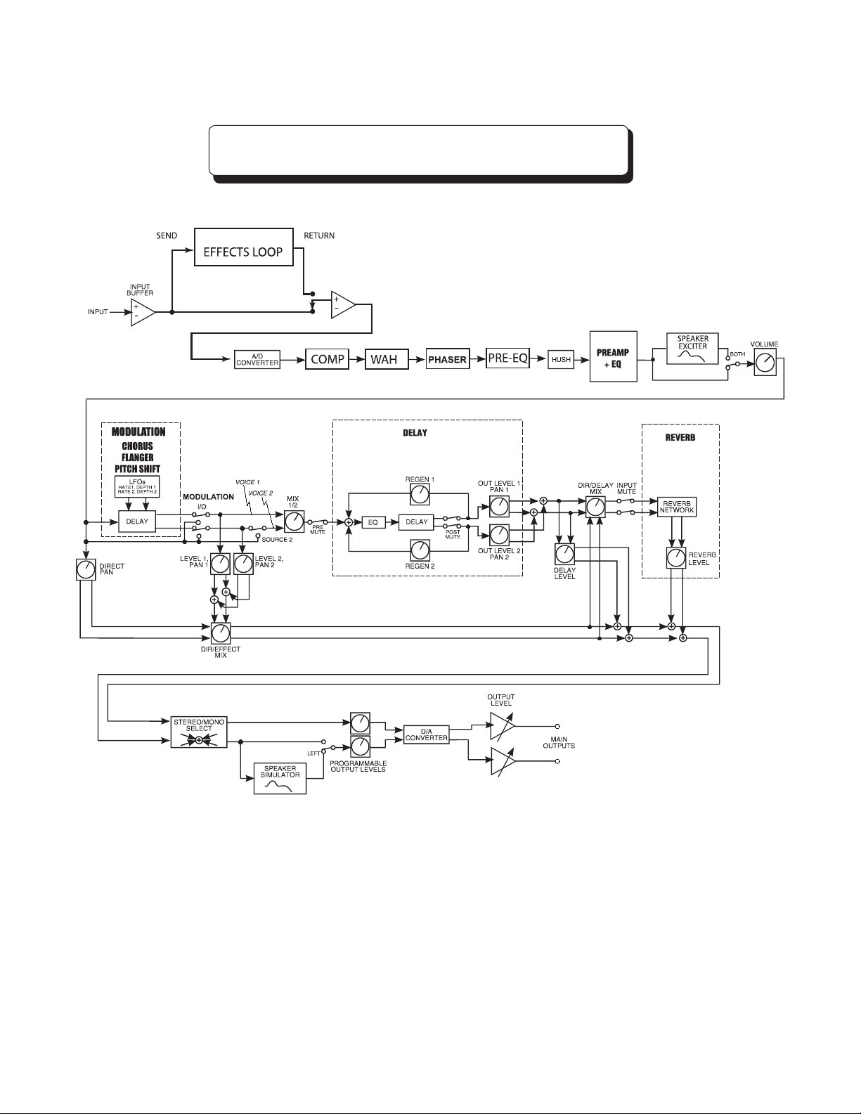
7. UTOPIA B300 Block Diagrams
WITH CHORUS, FLANGER AND PITCH
SHIFT MODULATION EFFECTS
45
Page 46
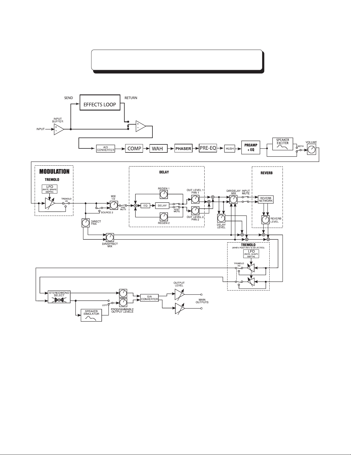
7. UTOPIA B300 Blocks
MODULATION EFFECT
WITH TREMOLO
46
Page 47

7. Function - Parameter - Range List
FUNCTION PARAMETER LIST RANGE
(via FUNCTION SELECT) (via PARAMETER SELECT) (via PARAMETER ADJUST)
GLOBAL OUTPUT (Output Level) Stereo, Mono
SPKR XTR (Speaker Exciter Lock) Unlock, Lock Off, Lock L, Lock B
HUSH OFFSET -10(dB) to +30(dB)
MASTER VOLUME -40(dB) to +6(dB)
MIXER VOLUME (Volume Level) 0 to 127
LEFT OUT LVL (Left Channel Output Level) OFF to +4(dB)
RIGHT OUT LVL (Right Channel Output Level) OFF to +4(dB)
MIX (Direct/Effect Mix Level) DIR <0 to 100> EFF
DIR PAN (Direct Signal Panning) L <0 to 100> R
DELAY LVL (Delay Signal Level) OFF to +4(dB)
REVERB LVL (Reverb Signal Level) OFF to +4(dB)
PREAMP CHANNEL DEEP, NORM, BRITE, DIST
GAIN (Gain Level) 0 to 10
VARIAC ADJUST (Variac Level Adjustment) -6(dB) to 0(dB)
BASS (Bass Level) 0 to 10
MID (Midband Level) 0 to 10
TREBLE (Treble Level) 0 to 10
PRESENCE (Presence Level) 0 to 10
BRIGHT In, Out (DEEP, NORM & BRITE)
SCOOP Out, In (DIST Only)
MASTER 0 to 10
SYMMETRY -28(dBu) to +6(dBu) default is 0.0
(dBu) (DIST Only
POLARITY + or - (DIST Only)
DX-FILTER 0 to 49 (DIST Only)
MIX DIR <50> DIS (DIST Only)
DIR LPF 0-64 (DIST Only)
HUSH HUSH (Hush In/Out) Out, In
EXP THRESH (Expander Threshold Level) -90(dB) to -27(dB)
EXCITER EXCITER (Speaker Exciter Status) Off, Left, Both
SPKR CURV (Speaker Curve) A, B, C, D, E
DEFINITION -15 to +15
SONIC BOOM -15(dB) to +15(dB)
COMPRESSOR COMPRESSOR (Compressor In/Out Status) Out, In
COMP THRESH (Compression Threshold) -24(dB) to 0(dB)
COMP ATTACK (Compression Attack) 1MS, 2MS, 4MS, 8MS, 16MS,
25MS, 50MS, 75MS
COMP RELEASE (Compression Release) .05S.to 2.0S
EFFECTS LOOP EFX LOOP Out, In
WAH-WAH WAH-WAH (Wah-Wah In/Out Status) Out, In
WAH FREQ (Wah Frequency) 310Hz to 2.6kHz
PHASER PHASER (Phaser In/Out Status) Out, In
DIR/EFF MIX DIR <0 to 100> EFF
DEPTH (Amount of Modulation) 0 to 100
P-RATE (Phaser Rate of Modulation) 0 to 254
RESONANCE (Amount of Feedback) 0 to 100
STAGES (Number of Stages) 4, 6
47
Page 48

7. Function - Parameter - Range List continued.....
FUNCTION PARAMETER LIST RANGE
(via FUNCTION SELECT) (via PARAMETER SELECT) (via PARAMETER ADJUST)
MODULATION MODULATION EFX Chorus, Flanger, Tremolo
EFX Pitch Shift
CHORUS CHORUS (Chorus In/Out Status) Out, In
LEVEL 1 (Voice 1 Level) OFF to +4(dB)
PAN 1 (Voice 1 Panning) L <0 to 100> R
DEPTH 1 (Voice 1 Modulation Depth) 0 to 100
RATE 1 (Voice 1 Modulation Rate) 0 to 254
DELAY 1 (Voice 1 Delay Length) 2ms to 40ms
LEVEL 2 (Voice 2 Level) OFF to +4(dB)
PAN 2 (Voice 2 Panning) L <0 to 100> R
DEPTH 2 (Voice 2 Modulation Depth) 0 to 100
RATE 2 (Voice 2 Modulation Rate) 0 to 254
DELAY 2 (Voice 2 Delay Length) 2ms to 40ms
FLANGER FLANGER (Flanger In/Out Status) Out, In
LEVEL 1 (Voice 1 Level) OFF to +4(dB)
PAN 1 (Voice 1 Panning) L <0 to 100> R
DEPTH 1 (Voice 1 Modulation Depth) 0 to 100
RATE 1 (Voice 1 Modulation Rate) 0 to 254
LEVEL 2 (Voice 2 Level) OFF to +4(dB)
PAN 2 (Voice 2 Panning) L <0 to 100> R
DEPTH 2 (Voice 2 Modulation Depth) 0 to 100
RATE 2 (Voice 2 Modulation Rate) 0 to 254
REGEN (Flanger Regeneration Level) OFF to +4(dB)
TREMOLO TREMOLO (Tremolo In/Out Status) Out, In
LOCATION (Pre or Post Reverb Location) Pre-Rev, Post-Rev
DEPTH (Modulation Depth) 0 to 100
T-RATE (Tremolo Modulation Rate) 0 to 254
SHAPE (Wave Shape) Triangle, Square
PITCH SHIFT PITCH SHIFT (Pitch Shift In/Out Status) Out, In
LEVEL (Pitch Shift Signal Level) OFF to +4(dB)
PAN (Pitch Shift Signal Panning) L <0 to 100> R
PITCH (Pitch Shift in 20-Cent Steps) -2400 to +1200
FINE (Pitch Shift in 1-Cent Steps) -20 to +20
SPEED (Pitch Shift Signal Speed) Slow, Medium, Fast
DELAY DELAY (Delay Status) Muted, Active
MUTE TYPE (Mute Type Status) Pre, Post, Both
DELAY LVL (Delay Level) OFF to +4(dB)
MIX (Source 1/Source 2 Mix Level) S1 <0 to 100> S2
SOURCE 2 (Source 2 Select) DIRECT, Voice 2
DLY HF DAMP (Delay High Frequency Damping) 0 to 99
OUT LEVEL 1 (Delay 1 Level) OFF to +4(dB)
PAN 1 (Delay 1 Panning) L <0 to 100> R
DLY TIME1 (Delay 1 Length) 0 to 2000ms
REGEN 1 (Delay 1 Regeneration) OFF to +4(dB)
OUT LEVEL 2 (Delay 2 Level) OFF to +4(dB)
PAN 2 (Delay 2 Panning) L <0 to 100> R
DLY TIME2 (Delay 2 Length) 0 to 2000ms
REGEN 2 (Delay 2 Regeneration) OFF to +4(dB)
48
Page 49

7. Function - Parameter - Range List continued.....
FUNCTION PARAMETER LIST RANGE
(via FUNCTION SELECT) (via PARAMETER SELECT) via PARAMETER ADJUST)
TAP QUANTIZING DELAY 1 Sixteen, Eighth, Triplet, Quarter,
Half, Whole, None
DELAY 2 Sixteen, Eighth, Triplet, Quarter,
Half, Whole, None
REVERB REV INPUT (Reverb Input Status) Muted, Active
MIX (Direct/Delay Mix Level) Dir <0 to 100> Dly
REVERB LVL (Reverb Signal Level) OFF to +4(dB)
REV DECAY (Reverb Decay Length) 0 to 99
REV HF DAMP (Reverb High Frequency Damping) 0 to 99
PEDAL NUMB 1 ADJ, IPED, IPSW, XPED, OFF
CONTROLLERS PARA1 Any parameters available in this
configuration can be selected.
ULIM C1 Any range in PARA1's selection
can be used.
LLIM C1 Any range in PARA1's selection
can be used.
NUMB 2 ADJ, IPED, IPSW, XPED, OFF
PARA 2 Any parameters available in this
configuration can be selected.
ULIM C2 Any range in PARA2's selection
can be used.
LLIM C2 Any range in PARA2's selection
can be used.
NUMB 3 ADJ, IPED, IPSW, XPED, OFF
PARA 3 Any parameters available in this
configuration can be selected.
ULIM C3 Any range in PARA3's selection
can be used.
LLIM C3 Any range in PARA3's selection
can be used.
PEDAL STATUS RUN STAT (Pedal Running Status On or Off) OFF,ON
PEDAL VOLUME 0 to 127
FOOTSWITCH EFX 1 Compressor, Solo, TBypass
MAPPING TOGGLE Deep, Norm, Brite, Dist
MIDI CHANNELS RECEIVE 1-16-OMNI, OFF (default is Omni)
TRANSMIT 1 -16, OFF (default is OFF)
MIDI DUMP/LOAD 1 PR DUMP/LOAD (1 Preset Dump/Load)
BULK DUMP/LOAD
FACTORY RESTR X to X (Restore a single preset) 1 to 1, 2 to 2, 3 to 3, etc.
RESTORE ALL RESTORE (Restore all factory presets) Enter Number 22 - Use caution
as this will over-write all presets!
VERSION NUMBER
TITLE EDIT XXXXXXXXX
49
Page 50
8. Operating the UTOPIA B300
8. Display Description
The LCD display on the Utopia B300 provides you with the information about the preset you are in:
When in PRESET MODE the LEDs will be lit "GREEN" and the display will show the following:
Top line of display will show:
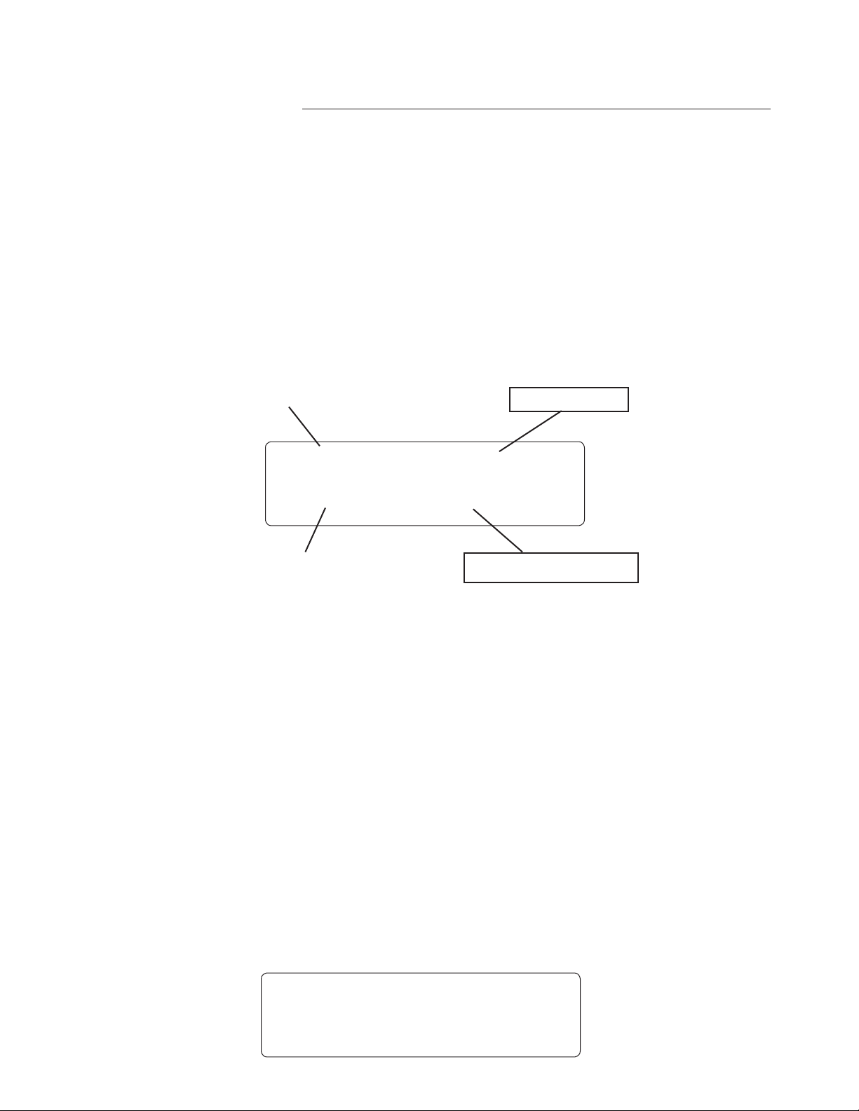
BANK - Displays the Preset Bank you have selected. - in the example below - B00
PRESET TITLE - This is the NAME of the preset - in the example below - BIG WAH WAH
Bottom line of display will show:
PRESET NUMBER - This is the number of the preset - in the example below - 4
EFFECTS USED IN PRESET - in the example below - Chr-Dly-Rev (Chorus-Delay-Reverb)
BANK NUMBER
PRESET NAME
B 0 0 B I G W A H W A H
4 C h R - D L Y - R E V
PRESET NUMBER
When in 2ND FUNCTION MODE the LEDs will be lit "YELLOW" with the 2nd Cancel (button 9)
LED lit "RED"
The display will remain the same as in preset mode with the following exceptions:
1) If Tru-Bypass has been selected for the Effect On/Off 2nd Function then Tru-Bypass will be shown
on the bottom line if selected.
2) If you have pressed the MUTE/TUNER button number 3, the TUNER will be shown in the display
EFFECTS ON PRESET
50
When in PRESET EDIT MODE (accessed by turning the FUNCTION SELECT knob) the display will
show the following:
Top line of display will show the FUNCTION selected - in the example below ***PREAMP***
Bottom line of display will show the first PARAMETER of the function - in the example below CHAN
NEL NORM
* * * P R E A M P * * *
C H A N N E L N O R M
-
Page 51
8. Selecting a preset:
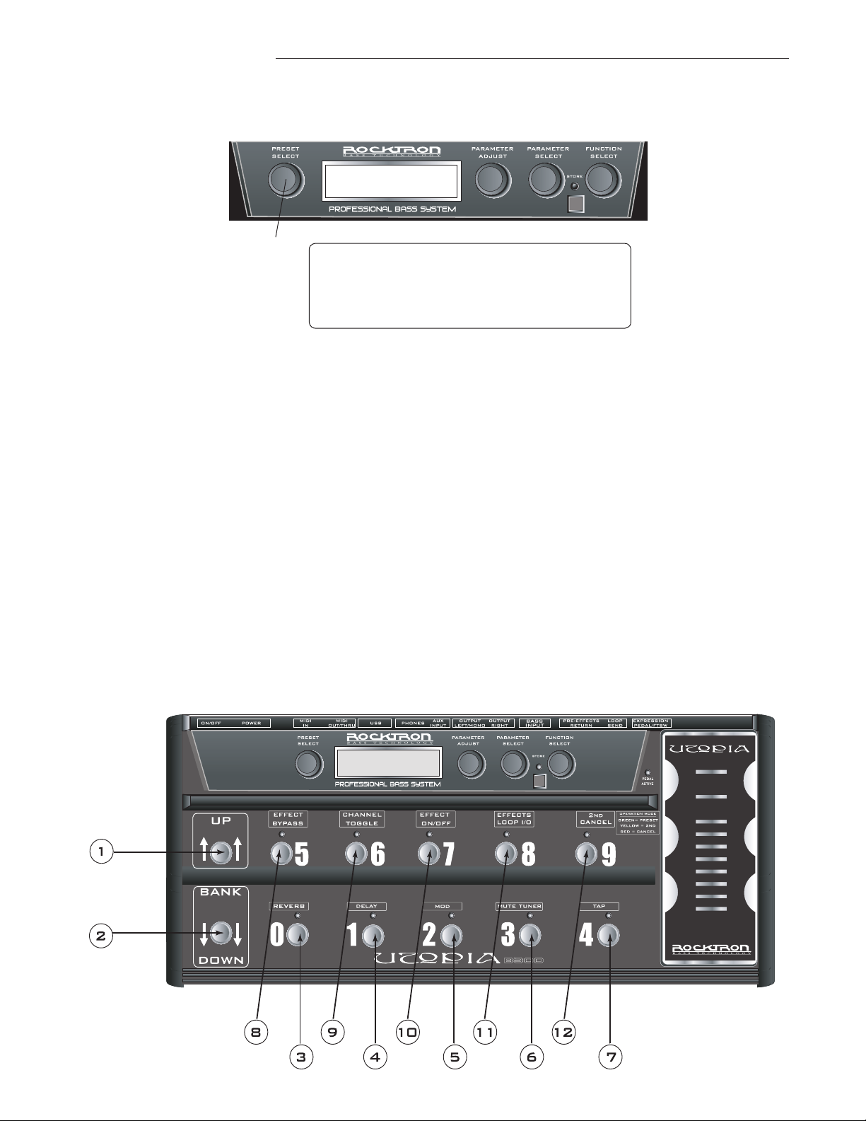
There are two ways to select a preset on the UTOPIA B300. You can either turn the PRESET knob to
the desired preset you wish to recall. The display will show the selected preset number.
1
b 0 4 d i r t y - c h o r u s
4 1 c h r - d l y - r e v
The second way to select a preset with the UTOPIA B300 is to use the footswitches. Use the BANK UP
and DOWN buttons (points 1 and 2 in the drawing below) to scroll through the BANKS. Then select a
preset using the buttons marked 0-9 (see points 3-12 below). Note that each button corresponds to the
last number in the preset of the bank selected. For example if you want to select preset 29, use the bank
up button until you reach bank B02 and then press button 9 - this is preset 29. To select preset 38, use
the bank up button until you see B03 in the display and then press button 8 - this is preset 38 and it will
appear in the window.
You will remain on the current preset until one of the preset buttons, marked 0-9 (points 3-12 below) is
pressed. This is a useful feature in a live situation allowing you to be ready to select the next sound you
would like to use in a song.
51
Page 52

8. Preset Banks:
The Utopia B300 has 13 banks of 10 presets each (not that there is no preset 0 or preset 129) for a total
of 128 presets. This is an ideal setup for live situations as you can arrange your sounds in each bank to
your suit your needs. You can use it to set up the 10 sounds you use all the time or set up each bank by
particular song.
The two line blue display will always show you what bank is selected (or to be selected) by the following indications:
The banks are arranged as follows:
BANK
CONTAINS PRESET NUMBERS
B00
B01
B02
B03
B04
B05
B06
B07
B08
B09
B10
B11
B12
1, 2, 3, 4, 5, 6, 7, 8, 9
10, 11, 12 ,13 ,14, 15 ,16 17, 18, 19
20, 21, 22, 23, 24, 25, 26, 27, 28, 29
30, 31, 32, 33, 34, 35, 36, 37, 38, 39
40, 41, 42, 43, 44, 45, 46, 47, 48, 49
50, 51, 52, 53, 54, 55, 56, 57, 58, 59
60, 61, 62, 63, 64, 65, 66, 67, 68, 69
70, 71, 72, 73, 74, 75, 76, 77, 78, 79
80, 81, 82, 83, 84, 85, 86, 87, 88, 89
90, 91, 92, 93, 94, 95, 96, 97, 98, 99
100, 101, 102, 103, 104, 105, 106, 107, 108, 109
110, 111, 112, 113, 114, 115, 116, 117, 118, 119
120, 121, 122, 123, 124, 125, 126, 127, 128
52
Page 53
8. Changing preset parameters:
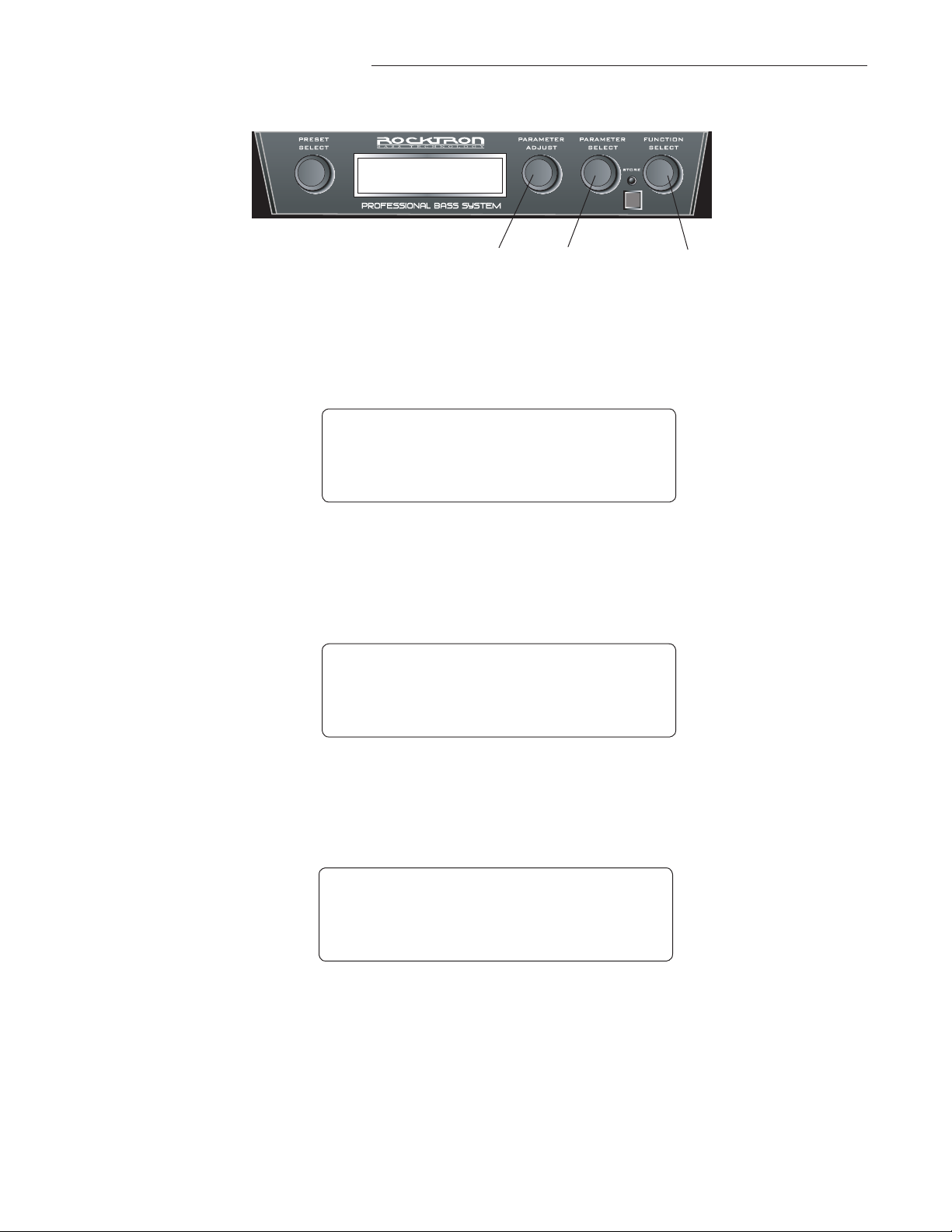
Step 1
Step 2
3
Turn the FUNCTION SELECT knob to select the function heading which contains the
parameter(s) you wish to change.
2
1
* * * * R E V E R B * * * *
R E V I N P U T M U T E D
Turn the PARAMETER SELECT knob to the specific parameter you wish to change.
* * * * R E V E R B * * * *
R E V D E C A Y 9 4
Step 3
Turn the PARAMETER ADJUST knob to alter the parameter value.
* * * * R E V E R B * * * *
R E V D E C A Y 3 2
NOTE: If you have changed a parameter the "STORE" LED will light. The change(s) that you made
will not be stored until you have pressed the "STORE" button. Please follow instructions on the next
page for details on how to store changed parameters.
53
Page 54
8. Storing changed preset parameters:
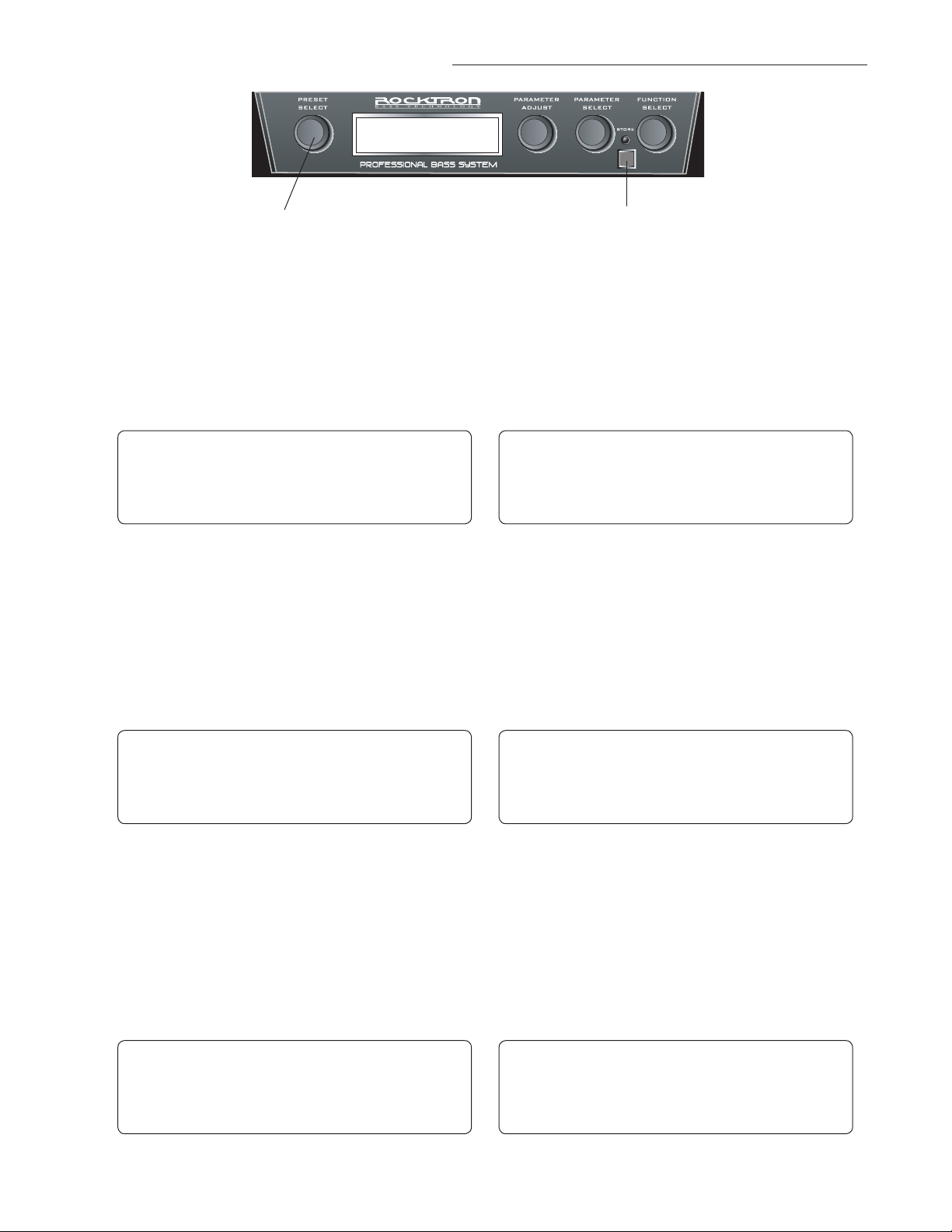
2
Step 1
While viewing a function or parameter title, press the STORE button to start the store
procedure. The display will now alternate between the destination preset number and
title and "STORE AT PRESET."
b 0 4 d i r t y - c h o r u s
4 1 c h r - d l y - r e v
Step 2
Turn the PRESET knob to select the desired preset number to store the new param
eter values into. (If you wish to store the new parameter values into the current preset
number, this step is not necessary.) The display will now alternate between the new
preset number and "STORE AT PRESET".
1,3,4
b 0 4 d i r t y - c h o r u s
S T O R E A T P R E S E T
-
54
b 0 5 i n v i s i b l e
5 7 T R E - D L Y - R E V
Step 3
Press the STORE button a second time to store the new values into the selected preset
number. The display will briefly flash "STORED". Next it will ask you if you would
like to also copy the title from the preset. (Turning the PARAMETER ADJUST knob
before completing this step will cancel the store procedure.)
B 0 5 i n v i s i b l e
s t o r e d
b 0 5 i n v i s i b l e
S T O R E A T P R E S E T
B 0 5 i n v i s i b l e
C O P Y T I T L E T O O ?
Page 55

8. Storing changed preset parameters continued.......:
Step 4
If you would like to copy the title - press the store button. The display will briefly
flash "STORED" and return to PRESET MODE. If you do NOT want to copy the
title simply turn the Parameter Adjust one click and the title will not be stored.
B 0 5 d i r t y - c h o r u s
5 7 c h r - d l y - r e v
NOTE: If a preset with altered parameters is exited before completing Step 3 and 4, all edited
parameter values will be lost. When saving altered parameters, make sure the display
flashed "STORED" before exiting the store procedure.
55
Page 56

8. Operation Mode
The Utopia B300 has two OPERATION MODES - Preset and 2nd. When in Preset mode you can
select any preset you would like in the various banks. When in 2nd Mode you are in the 2nd function
mode of the selected preset. The 2nd Function mode allows you to turn on and off various aspects of
the preset.
PRESET MODE
In the PRESET MODE the LEDs on the pedal board will be lit "GREEN".
When in this mode you can select any preset in any bank that you would prefer.
2ND FUNCTION
MODE
To enter into the 2ND FUNCTION MODE, press the already selected preset a
second time. The LEDs on the pedal board will turn "YELLOW" with the 2ND
CANCEL button number 9 LED will be lit "RED". Once in the 2ND FUNC
TION MODE you can turn on and off various effects within the selected presets.
Here is a list of those effects that can be accessed within each preset in the 2ND
FUNCTION MODE:
BUTTON NUMBER 2ND FUNCTION
0
1
2
REVERB - turns on and off the reverb within the preset.
DELAY - turns on and off the delay within the preset.
MOD - turns on and off the modulation effect (chorus, flanger, pitch shift or
tremolo within the preset.
3
MUTE/TUNER - pressing this button will MUTE the output and turn on the
built-in Tuner so that you can tune in silence.
-
56
4
TAP - this button allows you to set the delay rates by tapping this button at the
tempo desired.
5
EFFECT BYPASS - turns on or off all the effects and bypasses them completely.
6
CHANNEL TOGGLE - allows you to toggle between two different channels
(for example, between DEEP and DIST)
7
EFFECT ON/OFF - turns on the assigned effect to that footswitch, either Compressor, Solo or Tru-Bypass (this must be set and stored in the Footswitch Mapping Function).
Note: At anytime while in 2nd Mode any changes to the ON/OFF states of the
switches may be saved into the current preset being used. This adds flexibility
when setting preset effect(s) ON/OFF recall states within a preset.
8
9
EFFECTS LOOP I/O - turns on or off the effects loop
2ND CANCEL - pressing this button allows you to exit the 2ND FUNCTION
MODE and return to PRESET MODE
Page 57
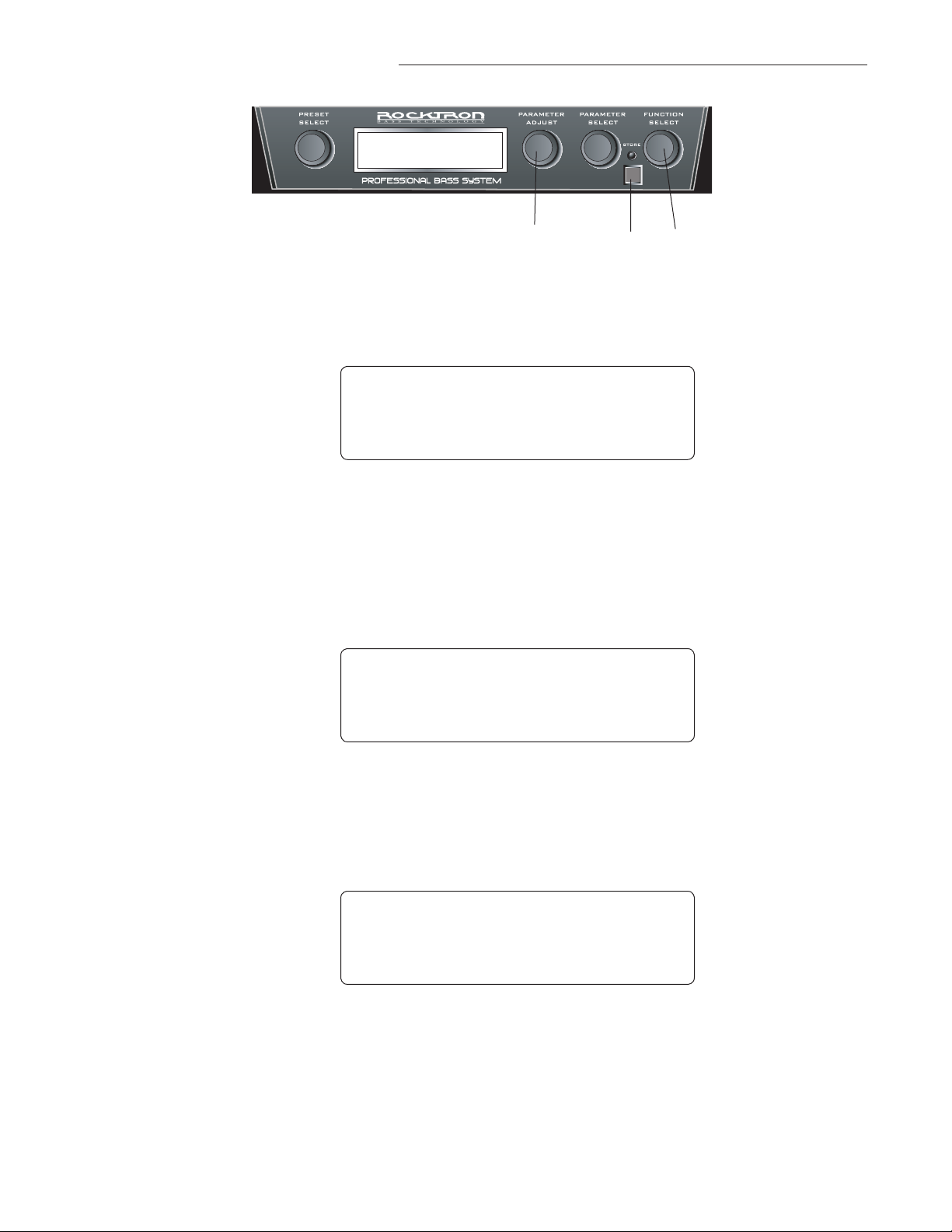
8. Selecting a Modulation Effect
1,32 4
Step 1
Step 2
Turn the FUNCTION SELECT knob to MODULATION EFX
* m O D U L A T I O N e f x *
* * C H O R U S * *
Turn the PARAMETER ADJUST knob to select Chorus, Flanger, Tremolo or Pitch
Shift
Note: When changed, the EFFECT will turn to a preset starting condition for you to
modify further or use directly.
* m O D U L A T I O N e f x *
* * f l a n g e r * *
Step 3
Step 4
Turn FUNCTION SELECT knob to right one click to access the selected effect's
function controls.
* * * F l a n g e r * * * *
f l a n g e r i n
Once you have made all of the adjustments to the selected effect and you would like
to save the changes you made, press store and follow the instructions under "STORING CHANGED PRESET PARAMETERS" in this manual.
57
Page 58

8. MUTE/ Harmonic Tuner Function
The Utopia B300 provides a built-in harmonic tuner which can be activated 2 different ways at any
time. This will MUTE the output of the B300 allowing you to tune in silence. Use 12th fret harmonics
to tune.
Step 1
Enter the turner mode using one of the 2 methods described below:
Method 1: After recalling any preset. Press and hold the preset button again. The
B300 after a few seconds will automatically activate the TUNER. You will notice the
MUTE TUNER red LED is on and the tuner is active. Once you have finished tun
ing PRESS the MUTE/TUNER footswitch to return to the preset you were currently
using.
Method 2: After recalling any preset. Press the preset button again to enter 2nd Mode.
You may choose to use the other switches to control other things before using the
tuner. When you want to use the tuner within 2nd Mode….Press the MUTE / TUNER
footswitch #3 to activate the TUNER.
You will notice the MUTE TUNER red LED is on and the tuner is active. Once you
have finished tuning PRESS the MUTE/TUNER footswitch to return to the preset you
were currently using.
-
c
Step 2
*
Pluck the harmonic at the 12th fret of the string you intend to tune. The B300 will de
tect the note and indicate its nearest even tempered pitch at the center of the display.
If the note is slightly above or below any of the 12 even-tempered notes, a sharp or
flat condition is indicated by an asterisk symbol in the bottom line of the display at
either side to the displayed note as shown below:
c
*
FLAT SHARP
-
58
Page 59

8. MUTE/Tuner F
unction continued.....
Here is a note that is slightly above C (i.e. slightly sharp)
c
*
FLAT SHARP
Here is a note that is slightly below C (i.e. slightly flat)
c
*
Step 3
Step 4
FLAT SHARP
As you tune the string, the displayed asterisk will move closer to the displayed note
on the top line. When the plucked note is perfectly in tune with the note that is displayed, "TUNED" will display on the bottom line
c
t u n e d - ^ - t u n e d
FLAT
To leave the TUNER and exit the MUTE function simply press button number 3
again. You will return to the preset you were on. Note that the LED will be lit RED
(like the 2ND FUNCTION CANCEL LED) to let you know that is the button to use
to exit the MUTE/TUNER mode.
SHARP
59
Page 60

8. USB Connection
You can connect the Utopia 300 directly to a computer via a standard USB cable (not included) and us
ing standard PC drivers. The USB in the B300 will pass audio and can be used to record directly into a
computer based recording system and receive the audio back into the B300. Consult your systems audio
interface or recording software documentation for more information.
Note: We suggest changing the Global Parameter to Stereo and turn on the Speaker Exciter for better
overall direct audio recording. Use the Master Volume of the B300 to adjust your signal level to the
USB host.
8. MIDI IN
The MIDI IN in the Utopia B300 will allow you to update your B300 with new presets directly from a
computer using any MIDI interface device. Follow the connection steps in the CONNECTIONS SECTION of this manual.
Please note that though the B300 is shipped with 7 Pin din connectors any standard 5 pin MIDI cord
may be used for device connections.
8. MIDI OUT/THRU
The MIDI OUT/THRU in the Utopia B300 will allow you to transmit and/or update your B300 with
new presets directly from a computer using any MIDI interface device. Follow the connection steps in
the CONNECTIONS SECTION of this manual.
You can also use this to connect to a MIDI receiving device that you want to control from the B300.
60
Page 61

8. MIDI CHANNELS - MIDI RECEIVE
The B300 can receive MIDI commands from other MIDI transmitting devices. In order for this function to operate properly, the B300's MIDI receive channels must be set to correspond to the MIDI
Channel that the other devices are sending MIDI messages on. The MIDI RECEIVE channel options
are 1-16, OMNI and OFF.
Step 1
Step 2
Step 3
Turn the FUNCTION SELECT knob to MIDI CHANNELS
M I D I C H A N N E L S
Turn the PARAMETER SELECT knob to "Receive Channel"
m i d i c h a n n e l s
r e c e v c h a n l o m n i
Turn PARAMETER ADJUST knob to select the appropriate Receive Channel 1-16,
Omni and OFF
Step 4
M I D I c h a n n e l s
r e c e v c h a n l 1 6
Once you have made all of the adjustments to the selected MIDI CHANNEL and
you would like to save the changes you made, press store and follow the instructions
under "STORING CHANGED PRESET PARAMETERS" in this manual
61
Page 62

8. MIDI CHANNELS - MIDI Transmit
The B300 can transmit MIDI commands to other MIDI receiving devices. You must however assign a
MIDI Transmit channel in order to do so. In the next section [ PROGRAM CHANGES ] you will learn
how to send program changes to your favorite piece of rack gear.
Step 1
Step 2
Step 3
Turn the FUNCTION SELECT knob to MIDI CHANNELS.
M I D I C H A N N E L S
Turn the PARAMETER SELECT knob to "Transmit Channel."
m i d i c h a n n e l s
t r a n s c h a n l o f f
Turn PARAMETER ADJUST knob to select the appropriate MIDI Channel 1-16 and
OFF.
62
Step 4
M I D I c h a n n e l s
t r a n s m i t 1 6
Once you have made all of the adjustments to the selected MIDI CHANNEL and
you would like to save the changes you made, press store and follow the instructions
under "STORING CHANGED PRESET PARAMETERS" in this manual.
Page 63

8. Program Changes:
PROG CH TX ON, MAP, OFF DEFAULT = OFF
1 -TX-PC-> 127 [PROGRAM TRANSMIT MAP]
Note: The TRANSMIT CHANNEL must be assigned found in
MIDI CHANNELS function so the
B300 can send out MIDI MESSAGES.
The B300 can send PROGRAM CHANGES to another MIDI capable device through the MIDI OUT/
THRU jack whenever you recall a preset . You may send any PROGRAM CHANGE number you desire adding extra flexibility when controlling a favorite piece of outboard gear.
PROG CH TX
ON The B300 will send PROGRAM CHANGES on a 1 to 1 basis.
If you recall PRESET 1 on the B300 it will send PROGRAM CHANGE 1 on the
assigned TRANSMIT CHANNEL .
MAP When set to MAP the B300 will send a different PROGRAM CHANGE NUMBER you
have selected to be sent using the 1 -TX PC→ 127 mapping !
Default mapping is 1 to 1.
HOW TO MAP PRESETS:
Using the 1 -TX PC→ 1 when you recall preset 1 it could send PROGRAM CHANGE 127
when set as 1 -TX PC→127
To MAP the -TX-PC→ is easy and here’s how you do it.
1. Turn the FUNCTION SELECT to PROGRAM CHANGES FUNCTION.
2. Use the PARAMETER SELECT CONTROL to select the -TX-PC display
3. To pick the preset to be mapped [ The preset you will recall ] TURNING the PARAMETER
SELECT will scroll 1,2,3,4,5,6, etc……
4. Now use the PARAMETER ADJUST to select the PRESET NUMBER you want sent out from
the B300.
EXAMPLE:
B300 1 -TX-PC→13 [RECEIVING DEVICE]
5. Once you have set this PRESS STORE to complete the mapping process for that preset. The
display will show “ STORED “ to indicate success.
Note: Every changed mapping needs to be stored before advancing to the next B300 preset us ing the PARAMETER SELECT.
63
Page 64

8. MIDI DUMP/LOAD
Any or all of the B300's presets may be dumped to another B300 a sequencer or MIDI utility program
using a PC midi interface to create a ( .syx ) file. This file may be uploaded to the Rocktron website to
share with other users. All the information about the presets you have created will be dumped consisting of parameter values, title characters and controller assignments. When dumping a single preset into
another B300, the dumped preset can be loaded into any preset location on the receiving unit.
Note: The B300 midi data when sent by external means such as a PC MIDI utility program you will
need to configure it as stated below.
Buffer size 264 bytes
No of buffers 16 both RX and TX
100ms between buffers be used initially as a starting point.
100ms after F7 [ optional ]
If a MIDI sequencer is used to store the data record the Sysex data in real-time or adhere to the parameters given above.
Step 1
Step 2
Step 3
Connect a standard MIDI cable from the MIDI OUT of the transmitting B300 to the
MIDI IN of the receiving B300. Consult MIDI Connection drawing for more information
If you are dumping a single preset to another B300, the transmitting B300 must have
that preset selected.
Turn FUNCTION SELECT knob to MIDI DUMP/LOAD.
M I D I D U M P / L O A D
64
Step 4
1 8 P R E D U M P / L O A D
On the receiving B300 use the PRESET Select control to select the preset location
where the received preset will be stored. Note that the preset currently stored at the
selected location will be lost when the new preset is received.
Page 65

8. MIDI DUMP/LOAD continued.....:
Step 5
Step 6
On the transmitting B300, press the STORE button to dump the preset. The transmit
ting B300 will display "DUMPED"
M I D I D U M P / L O A D
d u m p e d
To BULK DUMP all presets to another B300 or upload them to a Sequencer or
Computer using a PC MIDI interface along with a MIDI Utility program, use the
PARAMETER SELECT knob, select BULK DUMP/LOAD and follow Steps 4 and 5
M I D I D U M P / L O A D
b u l k d u m p / l o a d
-
65
Page 66

8. Pedal Controllers
The "Pedal Controllers" function allows for specific UTOPIA B300 adjustable parameters to be mapped
(or assigned) to four available assignments:
1) PARAMETER ADJUST knob (ADJ)
2) The built-in EXPRESSION PEDAL (IPED - internal pedal)
3) The built-in EXPRESSION PEDAL FOOTSWITCH (IPSW - Pedal/Footswitch)
4) The external EXPRESSION PEDAL/FTSW Jack (XPED - external pedal)
These controllers will allow for real-time control over the selected parameter.
PARAMETER ADJUST knob (ADJ).
The "ADJ" selection in PEDAL CONTROLLERS section option lets you assign the PARAMETER
ADJUST knob for "quick adjust". Many people use this control as a Master volume, but you can assign
this to any of the B300's parameters. The default setting of this controller is mapped to MASTER
VOLUME.
EXPRESSION PEDAL (IPED) - internal pedal
The IPED selection in the PEDAL CONTROLLERS section options lets you assign up to three different
parameters that can be adjusted in real time by the built-in EXPRESSION PEDAL . Many people use
this for wah, volume, pitchshift and other effects.
EXPRESSION PEDAL FOOTSWITCH (IPSW - internal pedal footswitch)
The ISPW selection in the PEDAL CONTROLLERS section options lets you assign up to three different
parameters that can be adjusted in real time by the built-in EXPRESSION PEDAL FOOTSWITCH. The
default setting is mapped *Wah On, but it is Off. *Unless preset name relates to WAH then the switch
will activate the WAH.
EXPRESSION PEDAL/FTSW jack (XPED
- external pedal)
The IPED selection in the PEDAL CONTROLLERS section options let you assign up to three different
parameters that can be adjusted in real time by using the optional Rocktron Utopia Expression pedal
(sold separately) or the Rocktron HEX Expression pedal or the Rocktron VFS2 footswitch.. The default
setting of this controller is mapped to off.
All of these PEDAL CONTROLLERS let you store an "upper" and "lower" parameter value limit which
the controller cannot exceed. For example, when using the expression pedal to send continuous control
changes to control the "PITCH" parameter, an upper limit of +300 can be set and a lower limit of 200 can be set — even though the actual parameter range available is from +1200 to -2400. When the
expression pedal is at its heel position in this example, the "PITCH" parameter will be at -200, while at
its toe position it will be at +300. Up to three controllers can be assigned for each individual preset.
To make adjustment to the PEDAL CONTROLLERS follow these steps:
66
3,5,7,9 122,4,6,8,10 1
Page 67

8. Pedal Controllers continued........
Step 1
Step 2
Step 3
To access the Pedal Controller function, turn the FUNCTION SELECT knob clockwise to
"PEDAL CONTROLERS".
p e d a l c o n t r o l e r s
Turn the PARAMETER SELECT knob for the first parameter of the Controller Assign func
tion. This parameter allows you to select a controller number for the NUMB 1 parameter to
respond to.
NOTE: This parameter (NUMB 1 only) also gives you the option of selecting "ADJ".
p e d a l c o n t r o l e r s
n u m b 1 a d j
Use the PARAMETER ADJUST knob to select the controller to be assigned to the NUMB 1
parameter (either ADJ, IPED, IPSW or OFF).
-
p e d a l c o n t r o l e r s
n u m b 1 i p e d
When "ADJ" is selected, the parameter assigned to the first controller (PARA 1) can be
instantly accessed by turning the PARAMETER ADJUST knob when the preset title is dis
played. This allows you to access a parameter that you adjust frequently without paging
through function headings and parameters. If you select "IPED" the parameter assigned to
the first controller (NUMB 1) will be adjusted by the built-in expression pedal. If you select
"OFF" the first controller will not be assigned to either the "ADJ or the IPED".
Step 4
Turn the PARAMETER SELECT knob to select "PARA 1". This parameter allows you to
select a parameter for the PARA 1 parameter to respond to.
p e d a l c o n t r o l e r s
p a r a 1 m i x d i r
Step 5
Use the PARAMETER ADJUST knob to scroll through the available parameters to be assigned to the PARA 1 parameter.
-
p e d a l c o n t r o l e r s
p a r a 1 p e d a l v o l u
67
Page 68

8. Pedal Controllers......continued.............
NOTE: Parameters available to be assigned may vary depending on what MODULATION effect you have selected for that
particular preset.
NOTE: Because character space on the display is limited, you may not see the entire name of a parameter. For example,
to choose FLANGER LEVEL 1 or FLANGER PAN 1 (or any of the Flanger's parameters), select "LEVEL 1" or "PAN 1"
parameter that immediately follows the "FLANGER" parameter when turning the PARAMETER ADJUST knob clockwise.
This is true for some other parameters as well.
Step 6
Turn the PARAMETER SELECT knob one step clockwise to display the Upper Limit
parameter (for PARA 1).
p e d a l c o n t r o l e r s
u l i m c 1 1 0 0
NOTE: The UTOPIA B300 allows you to select an upper and lower value limit which the parameter
cannot exceed. For example, if a parameter has a value range from 0 to 127, yet you would like the
range of the parameter to vary from only 50 to 127, you may set a lower limit of 50 and an upper limit
of 127 via the Upper (ULIM) and Lower Limit (LLIM) parameters. When a parameter is stored in the
Pedal Controller function (Step 7), the maximum parameter value is automatically stored as the upper
limit (expression pedal toe down), while the minimum value is stored as the lower limit (expression
pedal heel down).
Step 7
Use the PARAMETER ADJUST knob to choose the highest value that the parameter
is not allowed to exceed when the toe of the expression pedal is down.
68
Step 8
Step 9
p e d a l c o n t r o l e r s
u l i m c 1 1 2 7
Turn the PARAMETER SELECT knob one step clockwise to access the Lower Limit
parameter (for PARA 1).
p e d a l c o n t r o l e r s
u l i m c 1 0
Use the PARAMETER ADJUST knob to select the lowest value which the parameter
is not to fall below through when the heel of the expression pedal is down.
p e d a l c o n t r o l e r s
u l i m c 1 5 0
Page 69

8. Pedal Controllers......continued.............
Selecting a lower limit value that is greater than the upper limit value will invert the response of
the controller - i.e. the toe position of the expression controller will provide the minimum value,
while the heel position will provide the maximum value.
Step 10
Step 11
Step 12
To make changes to the second Pedal Controller turn the PARAMETER SELECT
knob clockwise one click.
p e d a l c o n t r o l e r s
n u m b 2 I P E d
Repeat steps 3-10 to make changes to NUMB 2, PARA 2, ULIM C2, LLIM C2,
NUMB 3, PARA3, ULIM C3, LLIM C3.
You now must store your changes. If you have made any changes to any parameter, the LED
above the "STORE" button will light. Press the STORE button to save the changes you have
made. "STORE AT PRESET" will flash intermittently with the current preset. If you would
like to save this change to the current preset, press the STORE button again. To save this adjusted preset (and the parameters you have just changed) to a different preset location, use the
PRESET SELECT knob to choose the preset and then press the STORE button again. Note
that doing this will "over-write" the preset you are saving to.
b 0 4 D I R T Y - c h o r u s
S T O R E A T P R E S E T
NOTE: To exit Pedal Controllers at any time or cancel any changes you have made, turn
either the PRESET or FUNCTION SELECT knob. The word CANCEL will flash on the display
and then return you to the preset you were working on..
b 0 4 C U R R Y D I N N E R
C a n c e l
b 0 4 C U R R Y D I N N E R
4 2 f l a - D L Y - R E V
B 0 4 C U R R Y D I N N E R
4 2 f l a - D L Y - R E V
69
Page 70
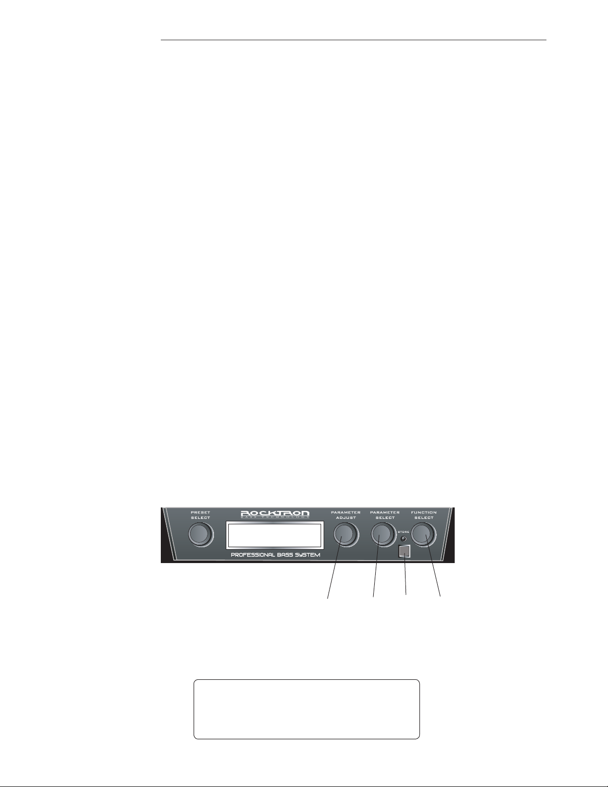
8. PEDAL STATUS
The PEDAL STATUS is for use with the built-in expression pedal. By setting the RUN STAT pa
rameter to ON, the UTOPIA B300 will track the position of the expression pedal (assuming the expression pedal is presently or had been previously assigned to "PEDAL VOLU") and vary the preset volume
accordingly from preset to preset. NOTE: When the RUN STAT is ON, the expression pedal will assume the last PEDAL VOLUME status received. Please see examples below:
Example 1..... lets assume that you had RUN STAT turned ON and that the preset you are using and
the preset you are switching to both have the expression Pedal Controllers assigned PEDAL VOLUME.
If you were to reduce the volume of the current preset with the expression pedal and then changed to
another preset, the new preset will assume the present position of the expression pedal. You WILL be
able to increase the volume of the new preset with the expression pedal as both presets had the expression Pedal Controllers assigned to PEDAL VOLUME.
Example 2 .... assuming you have RUN STAT turned ON and you have reduced the volume of the
current preset with the expression pedal and changed to a preset where the expression Pedal Controllers were assigned to control the Pitch Shift or Chorus or Reverb, etc. the new preset will assume the
previous preset's pedal volume. However, you will NOT be able to use the pedal to increase the volume
as you did in example 1. With RUN STAT turned ON, you would need to switch back to a preset that
had the expression Pedal Controllers assigned to pedal volume, use the expression pedal to increase the
volume and then switch back to the other preset.
-
This is something you should take into consideration when using the RUN STAT function.
The PEDAL STATUS parameter displays the current preset volume as determined by the pedal posi
tion.
NOTE: When the RUN STAT parameter is set to OFF, the UTOPIA B300 only recognizes
volume changes from the expression pedal if PEDAL VOLUME is assigned to the pedal and it
has been physically moved by the user.
12,43 5
Step 1
Turn the FUNCTION SELECT knob clockwise until PEDAL STATUS is displayed.
-
70
p e d a l s t a t u s
r u n s t a t o f f
Page 71

8. Pedal Status......continued.............
Step 2
Step 3
Turn the PARAMETER ADJUST knob to select ON for the RUN STAT parameter.
p e d a l s t a t u s
r u n s t a t o n
Turn the PARAMETER SELECT knob one step clockwise to the IPED/VOL param
eter.
p e d a l s t a t u s
i p e d / v o l 1 2 7
-
Step 4
The IPED/VOL will only change in real time if the Internal pedal has been assigned
to the IPED/VOL parameter. Otherwise to check pedal operation please view the parameter that it is assigned to. I.E.: If assigned to Chorus Rate got to the Chorus Function and look at the RATE parameter and move the pedal. You should see the value
changing.
There is also a XPED status which only shows you the current STATUS of the port. It
may be used to confirm the operation of that port.
p e d a l s t a t u s
X p e d s t a t u s
The PEDAL VOLUME parameter displays the current preset volume as determined
by the pedal position. Move the expression pedal up and down and you will see the
volume values change as the pedal moves.
71
Page 72

8. Pedal Status......continued.............
Step 5
b 0 4 D I R T Y - c h o r u s
S T O R E A T P R E S E T
NOTE: To exit Pedal Controllers at any time or cancel any changes you have made, turn either the
PRESET or FUNCTION SELECT knob. The word CANCEL will flash on the display and then return
you to the preset you were working on.
You now must store your changes. If you have made any changes to any parameter, the LED
above the "STORE" button will light. Press the STORE button to save the changes you have
made. "STORE AT PRESET" will flash intermittently with the current preset. If you would
like to save this change to the current preset, press the STORE button again. To save this adjusted preset (and the parameters you have just changed) to a different preset location, use the
PRESET SELECT knob to choose the preset destination and then press the STORE button
again. Note that doing this will "over-write" the preset location you are saving to.
b 0 4 C U R R Y D I N N E R
4 2 f l a - D L Y - R E V
b 0 4 C U R R Y D I N N E R
c a n c e l
b 0 4 C U R R Y D I N N E R
4 2 f l a - D L Y - R E V
72
Page 73
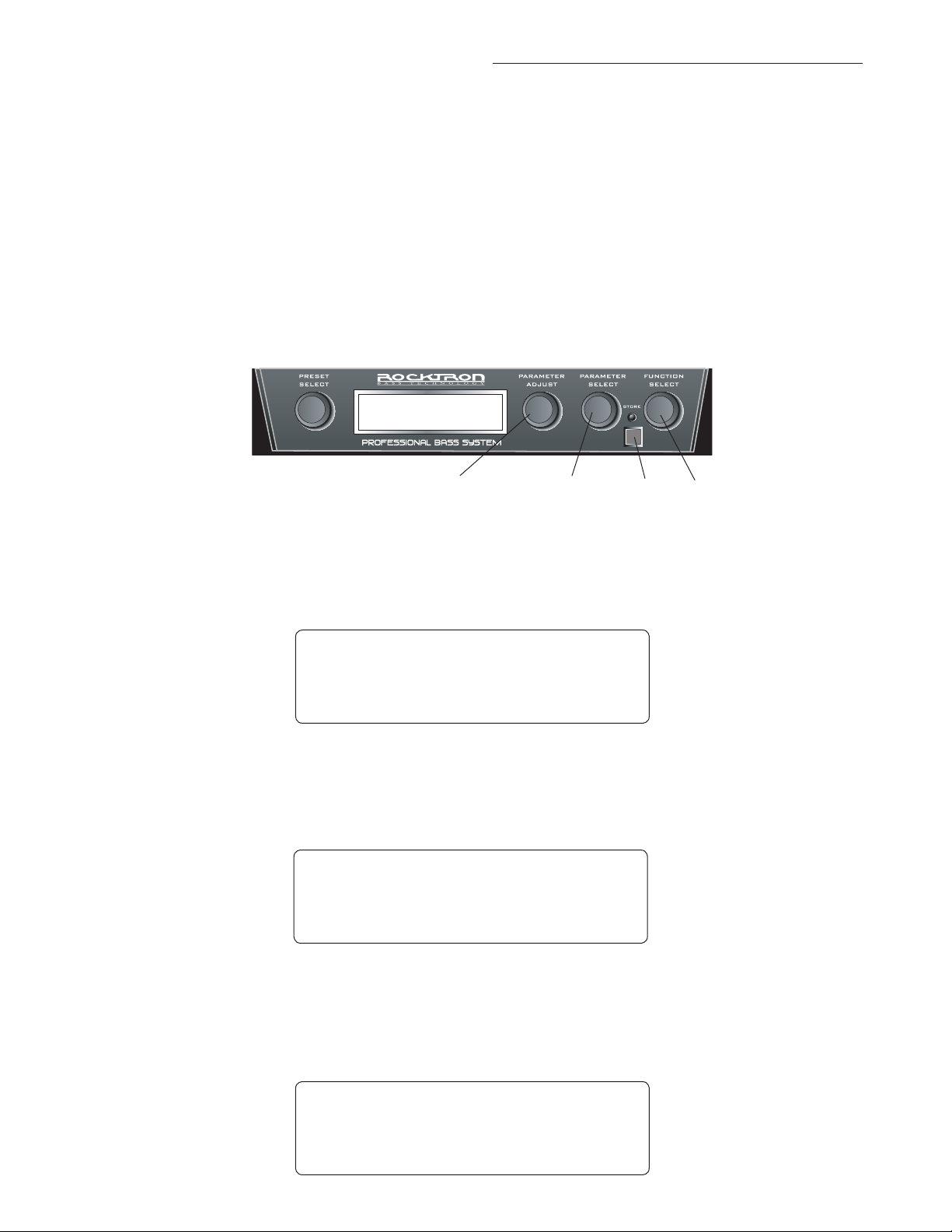
8. Foot SW Mapping (Footswitch Mapping)
The "FOOT SW MAPPING" function allows you to select what effect will be used in the 2ND
FUNCTION MODE when accessing the EFFECT ON/OFF (Second Function button number 7) and
what CHANNEL you will "toggle" to when accessing the CHANNEL TOGGLE (2nd Function button
number 6).
When using EFX 1 option you can map the footswitch to one of the following:
COMPRESSO (Compressor) - Turns the COMPRESSOR On and OFF within the preset
SOLO - Gives the output a 4dB boost within the preset.
TBYPASS - (Tru-Bypass) - this bypasses all electronic processing of the B300.
3,5 62,4 1
Step 1
Step 2
Step 3
To access the FOOT SW MAPPING function, turn the FUNCTION SELECT knob clockwise
to "FOOT SW MAPPING".
F o o t s w m a p p i n g
e f x 1 t b y p a s s
Turn the PARAMETER SELECT knob to select EFX 1.
f o o t s w m a p p i n g
e f x 1 C o m p r e s s o
Use the PARAMETER ADJUST knob to select Compressor, Solo or TBypass (Tru-Bypass).
f o o t s w m a p p i n g
e f x 1 s o l o
73
Page 74

8. Foot SW Mapping (Footswitch Mapping) continued.....
Step 4
Step 5
Turn the PARAMETER SELECT knob to select TOGGLE.
f o o t s w m a p p i n g
t o g g l e D E E P
Use the PARAMETER ADJUST knob to select DEEP, NORM, BRITE or DIST.
f o o t s w m a p p i n g
t o g g l e B R I T E
Step 6
Press the STORE button to save the changes. You now have assigned functions to
footswitches 6 and 7 in the 2ND FUNCTION MODE!
74
Page 75
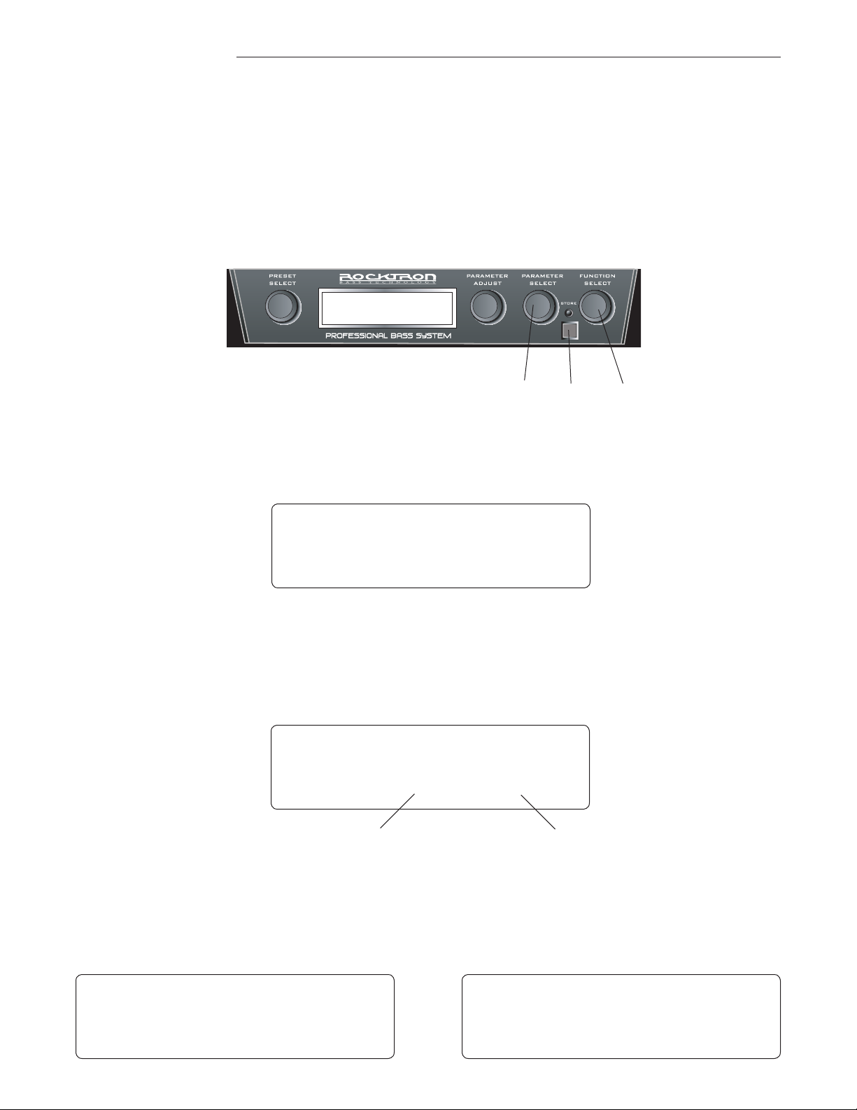
8. Factory Restore
The Factory Restore function allows you to restore presets 1-64 that you may have altered to their
original condition as shipped from the factory. Either the entire UTOPIA B300 memory can be restored
or a single preset can be restored. Note that you do NOT need to restore presets 65 to 128 as these are
factory preset that can not be altered and stored.
Restoring a single factory preset:
32 1
Step 1
Step 2
Turn the FUNCTION SELECT knob clockwise to "FACTORY RESTORE".
f a c t o r y r e s t o r e
Turn the PARAMETER SELECT knob one step clockwise to "RESTR 1 TO 1". The
number on the left is the original factory preset number to be restored. The number
on the right is the preset location that the preset will be stored into.
f a c t o r y r e s t o r e
r e s t r 1 t o 1
Factory preset
to be restored
Current Preset
location
Step 3
Press the STORE button to restore the preset. The display will flash "RESTORED"
and return to the preset name page.
f a c t o r y r e s t o r e
r e s t o r e d
b 0 0 u t o p i a r o c k s
1 p s h - d l y - r e v
75
Page 76
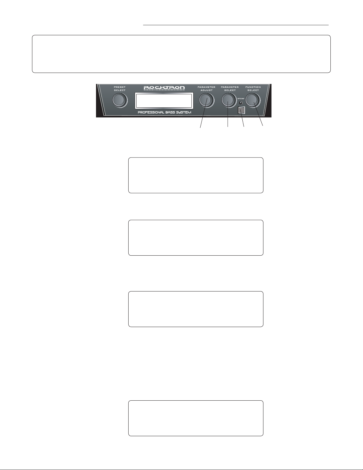
8. Restoring all factory presets
This procedure will permanently erase all presets (1-128) and replace them with the original
factory presets. If you have altered and stored presets which you do not want to erase, do not
!! CAUTION !!
perform the following procedure.
Step 1
Step 2
Step 3
4
3
Turn the FUNCTION SELECT knob clockwise to "FACTORY RESTORE".
2
1
f a c t o r y r e s t o r e
Turn the PARAMETER SELECT knob 2 steps clockwise to "ALL RESTORE 0".
f a c t o r y r e s t o r e
A L L R E S T O R E 0
A specific code number must be entered to restore the UTOPIA B300 memory
PARAMETER ADJUST knob to enter the number "22".
Use the
f a c t o r y r e s t o r e
76
A L L R E S T O R E 2 2
! ! WARNING ! !
Pressing the STORE button at this time will permanently erase all user presets and replace
them with the original factory presets. If you have altered and stored presets which you do not
want to erase, turn the FUNCTION SELECT control to exit this function.
Step 4
Press the STORE button at this time to initiate the All Restore procedure and erase
presets 1-128, replacing them with the original factory presets. The display will flash
"RESTORED" as the UTOPIA B300 memory is restored.
f a c t o r y r e s t o r e
r e s t o r e d
The display will return to Preset 1
Page 77
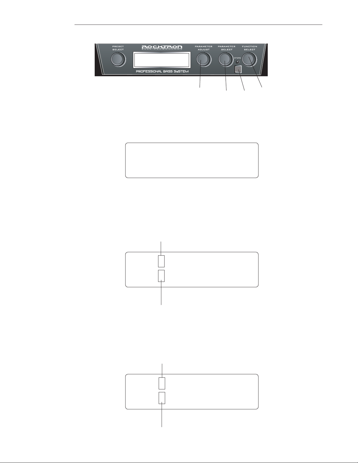
8. Title Edit:
3 52,4 1
Step 1
Step 2
To begin the Title Edit function, turn the FUNCTION SELECT knob clockwise until
the UTOPIA B300 displays "TITLE EDIT".
* * t i t l e e d i t * *
Turn the PARAMETER SELECT knob clockwise to initiate the Title Edit mode.
Turning this knob will also select the character above the part of the current title to be
edited. The letter to be adjusted will have a flashing box over the character selected.
(Flashing box)
* * t i t l e e d i t * *
b 0 5 D I R T Y - c h o r u s
Step 3
(Letter to be edited)
Use the PARAMETER ADJUST knob to select the desired character for the current
position (flashing box).
(Flashing box)
* * t i t l e e d i t * *
b 0 5 m D I R T Y - c h o r u s
(Letter to be edited)
77
Page 78

8. Title Edit continued......:
Step 4
To edit the next character in the next position, turn the PARAMETER SELECT knob
one step clockwise. The flashing box will move to the next character to be adjusted.
(Flashing box)
* * t i t l e e d i t * *
b 0 5 m D I R T Y - c h o r u s
(Letter to be edited)
Step 5
After all the characters have been edited as needed, press the STORE button to
save the new title to memory. The
UTOPIA B300
will flash "STORED" briefly.
b o 5 m a n h a t t a n
5 7 f l a - d l y - r e v
NOTE: The STORE button must be pressed to save the new title. Exiting the Title Edit function before pressing the STORE button will erase any editing that was done in Title Edit. Also,
after flashing "STORED", the UTOPIA B300 will exit the title edit mode and return to the main
preset number.
78
Page 79

8. Selecting a Power on Preset:
The UTOPIA B300 allows you to store a Power On preset which will always be recalled when
the unit is turned on.
1 2
Step 1
Turn the PRESET knob to the preset number you wish to be recalled each time the
unit is turned on.
B 0 0 P I N K D A Y S 1
7 C H R - D L Y - R E V
Step 2
B 0 0 P I N K D A Y S 1
P W R O N P R S T O R E D
In the above example, preset 7 has been saved so that when you turn the UTOPIA B300 on in
the future, preset 7 will be the preset that is recalled.
Press the STORE button. The screen will flash PWR ON PR STORED and then return to the preset name page.
B 0 0 P I N K D A Y S 1
7 C H R - D L Y - R E V
79
Page 80

9. SPECIFICATIONS
Specifications
Input Impedance 1M Ohm
Input Jack ¼" mono
Maximum Output Level +4 dBu
Important: Listening to any sounds at levels
above 85 dBu may cause hearing damage!
Due to high output capabilities present in
the HEADPHONE OUTPUTS it is recom-
mended to only use headphones that have
an integrated volume control. You may also
set the volume when the display is showing
a preset name by turning the PARAMETER
ADJUST control which is mapped directly
to the MASTER VOLUME of the B300.
Aux Input Jack
Power Requirements 9VAC / 2.9A min. Depending on where you
are located in the world you may receive a
2 .9A, 3A, 3.5A adapter with USA or Euro
style plugs.
Maximum Input Level 0 dBu
Output Jacks ¼" Left and Right.
Headphone Jack 1/8" Stereo (Load Impedance 32 Ohm Min)
1/8" Stereo
80
20 1/4" Wide x 9" Deep x 3 1/4" Tall
510mm Wide x 228mm Deep x 83mm Tall
With toe of expression pedal up
20 1/4" Wide x 9" Deep x 4 7/8" Tall
510mm Wide x 228mm Deep x 124mm Tall
3.85kg
Dimensions With toe of expression pedal down
Weight 8.5lbs
Page 81

10. Utopia B300 Preset Listing
# Preset Name What it does Pedal Heel Toe
1 UTOPIA ROCKS Clean Volume Volume Off Volume Full On
2 B’ChorusED Clean with Chorus Volume Volume Off Volume Full On
3 BASE---EDGE Distortion with Delay Volume Volume Off Volume Full On
4 BIG Wah Wah Light Distortion with Wah Wah and Delay Wah Frequency 150 1290
5 BASE BALLZ Light Distortion with a quick Delay Volume Volume Off Volume Full On
6 B’FLANGED Clean with Flanger Volume Volume Off Volume Full On
7 PINK DAYS 1 Clean with Phaser, Delay and Reverb Volume Volume Off Volume Full On
8 PINK DAYS 2 Clean with Tremolo and Reverb Tremolo Depth 25 100
9 FOOT PHASE Clean with Phaser Phaser Rate 12 190
10 LOW FIVE Clean with Pitch Shifted 5th added Volume Volume Off Volume Full On
11 TAIKA LEAD Distortion with Delay Volume Volume Off Volume Full On
12 BASS CRUNCH Distortion w/Chorus Delay and Reverb Gain 6.6 10
13 LIQUID BASS Clean with Chorus and Reverb Chorus Level OFF +4
14 COMPRESS IT! Clean with Chorus, Delay and Reverb Compressor OUT IN
15 LUCKY MAN Distortion with Pitch Shift and Delay Pitch 0 1200
16 CLEAN WAH Clean with Wah Wah Frequency 300 1290
17 SWEEPING UP Clean with Chorus Treble 0 10
18 PHASE AROUND Clean with Phaser MIX DIR <0 <50>
19 MR. SQUIRE Clean with Tremolo and Reverb Tremolo Depth 0 100
20 FUZZ-O-MATIC Light Distortion with Delay and Reverb Gain 0.33 10
21 STANLEY’S WAY Clean with Chorus and Reverb Reverb Level -45 -6
22 CRYIN BABY Distortion with Wah, Delay and Reverb Wah Frequency 300 1290
23 BLUE PHASE Clean with Phaser, Delay and Reverb Phaser Depth 0 100
24 MONSTER BASS Distortion with Flanger, Delay and Reverb Volume Volume Off Volume Full On
25 HVY STEPDOWN Distortion with Pitch Shift and Delay Pitch Shift One Step Down-200 00 = Normal Pitch
26 CLN STEPDOWN Clean with Pitch Shift and Reverb Pitch Shift One Step Down -200 00 = Normal Pitch
27 PITCH AROUND Clean with Pitch Shift and Reverb MIX DIR <0 <20
28 OVERCOAT Clean with Wah and Delay Wah Frequency 428 1290
29 TOP HAT Light Distortion with Wah and Delay Wah Frequency 338 1290
30 TREM PEDAL Clean with Delay Tremolo RATE 0 254
31 DIST.+Gain Distortion with Delay and Pitch Shift Gain 1.3 10
32 SMOOTH DOWN Clean with Delay and Reverb Volume Volume Off Volume Full On
33 I’M DA WALRS Distortion with HEAVY Delay Volume Volume Off Volume Full On
34 HIGH STAR Distortion with Delay and Reverb Volume Volume Off Volume Full On
35 BLACK PHASE Light Distortion with Phaser and Reverb Phaser Depth 0 100
36 BIG BOTTOM Distortion with Pitch, Delay and Reverb Pitch -1200 0
37 DREAM DREAM Clean with Flanger, Delay and Reverb Flanger Level OFF +4
38 WIDE BASS 1 Clean with Chorus and Reverb Volume Volume Off Volume Full On
39 WIDE BASS 2 Light Distortion with Chorus and Reverb Volume Volume Off Volume Full On
40 DEEP HOLE Clean with LONG Reverb DECAY MIX DIR 100> <1
41 DIRTY-Chorus Distortion with Chorus and Delay Chorus Level OFF +4
42 DIRTY-FLANGE Distortion with Flanger and Delay Flanger Level OFF +4
43 CURRY DINNER Clean with Reverb and Pitch Shift Volume Volume Off Volume Full On
44 VOLUME SWELL Clean with Pitch Shift Delay and Reverb Volume Volume Off Volume Full On
45 DROP IT! Distortion with Pitch Shift and Delay Pitch Shift -1200 0
46 BASS-N-ORGAN Clean with Pitch Shift Delay and Reverb Volume Volume Off Volume Full On
47 MID SWEEP Distortion with Chorus and Delay Preamp Mid 0 10
48 WET BASEMAN Clean with Chorus and Reverb Chorus Level OFF +4
49 DIRTY-D-VERB Distortion w/Pitch Shift Delay and Reverb Delay Out Level OFF +4
50 HI-FRETLEAD1 Distortion with Pitch Shift and Delay Pitch Level OFF +4
51 HI-FRETLEAD2 Distortion with Pitch Shift and Delay Pitch Level OFF +4
52 UP-THE-Gain Distortion Gain 1.3 10
53 FLANGY B100 Clean with Flanger and Reverb Flanger Level OFF +4
54 PHASEY B100 Clean with Phaser and Reverb MIX DIR <0 100>
55 ELECTRIC GTR Distortion with Delay and Reverb MIX DIR <0 <50>
56 TREMOLUX Clean with Tremolo and Reverb Tremolo Depth 0 100
57 INVISIBLE Clean with Tremolo Delay and Reverb Tremolo Depth 0 100
58 WEEPING B100 Clean with Wah and Reverb Wah Frequency 400 1290
59 DIRTY DAY Distortion with Phaser and Reverb MIX DIR <0 100>
60 BOUNCEBASS Clean with Delay Volume Volume Off Volume Full On
61 MEAN LEAD Distortion with Phaser Delay and Reverb Resonance 0 100
62 HEAVY BONES Distortion with Pitch Shift Pitch Level OFF +4
63 BASS JET Distortion with Flanger and Delay Flanger Level OFF +4
64 UNDERTOW Clean with Chorus Delay and Reverb Chorus Level OFF +4
81
Page 82

10. Utopia B300 Preset Listing
# Preset Name What it does Pedal Heel Toe
65 UTOPIA ROCKS Clean Volume Volume Off Volume Full On
66 B’ChorusED Clean with Chorus Volume Volume Off Volume Full On
67 BASE---EDGE Distortion with Delay Volume Volume Off Volume Full On
68 BIG Wah Wah Light Distortion with Wah Wah and Delay Wah Frequency 150 1290
69 BASE BALLZ Light Distortion with a quick Delay Volume Volume Off Volume Full On
70 B’FLANGED Clean with Flanger Volume Volume Off Volume Full On
71 PINK DAYS 1 Clean with Phaser, Delay and Reverb Volume Volume Off Volume Full On
72 PINK DAYS 2 Clean with Tremolo and Reverb Tremolo Depth 25 100
73 FOOT PHASE Clean with Phaser Phaser Rate 12 190
74 LOW FIVE Clean with Pitch Shifted 5th added Volume Volume Off Volume Full On
75 TAIKA LEAD Distortion with Delay Volume Volume Off Volume Full On
76 BASS CRUNCH Distortion w/Chorus Delay and Reverb Gain 6.6 10
77 LIQUID BASS Clean with Chorus and Reverb Chorus Level OFF +4
78 COMPRESS IT! Clean with Chorus, Delay and Reverb Compressor OUT IN
79 LUCKY MAN Distortion with Pitch Shift and Delay Pitch 0 1200
80 CLEAN WAH Clean with Wah Wah Frequency 300 1290
81 SWEEPING UP Clean with Chorus Treble 0 10
82 PHASE AROUND Clean with Phaser MIX DIR <0 <50>
83 MR. SQUIRE Clean with Tremolo and Reverb Tremolo Depth 0 100
84 FUZZ-O-MATIC Light Distortion with Delay and Reverb Gain 0.33 10
85 STANLEY’S WAY Clean with Chorus and Reverb Reverb Level -45 -6
86 CRYIN BABY Distortion with Wah, Delay and Reverb Wah Frequency 300 1290
87 BLUE PHASE Clean with Phaser, Delay and Reverb Phaser Depth 0 100
88 MONSTER BASS Distortion with Flanger, Delay and Reverb Volume Volume Off Volume Full On
89 HVY STEPDOWN Distortion with Pitch Shift and Delay Pitch Shift One Step Down-200 00 = Normal Pitch
90 CLN STEPDOWN Clean with Pitch Shift and Reverb Pitch Shift One Step Down -200 00 = Normal Pitch
91 PTICH AROUND Clean with Pitch Shift and Reverb MIX DIR <0 <20
92 OVERCOAT Clean with Wah and Delay Wah Frequency 428 1290
93 TOP HAT Light Distortion with Wah and Delay Wah Frequency 338 1290
94 TREM PEDAL Clean with Delay Tremolo RATE 0 254
95 DIST.+Gain Distortion with Delay and Pitch Shift Gain 1.3 10
96 SMOOTH DOWN Clean with Delay and Reverb Volume Volume Off Volume Full On
97 I’M DA WALRS Distortion with HEAVY Delay Volume Volume Off Volume Full On
98 HIGH STAR Distortion with Delay and Reverb Volume Volume Off Volume Full On
99 BLACK PHASE Light Distortion with Phaser and Reverb Phaser Depth 0 100
100 BIG BOTTOM Distortion with Pitch, Delay and Reverb Pitch -1200 0
101 DREAM DREAM Clean with Flanger, Delay and Reverb Flanger Level OFF +4
102 WIDE BASS 1 Clean with Chorus and Reverb Volume Volume Off Volume Full On
103 WIDE BASS 2 Light Distortion with Chorus and Reverb Volume Volume Off Volume Full On
104 DEEP HOLE Clean with LONG Reverb DECAY MIX DIR 100> <1
105 DIRTY-Chorus Distortion with Chorus and Delay Chorus Level OFF +4
106 DIRTY-FLANGE Distortion with Flanger and Delay Flanger Level OFF +4
107 CURRY DINNER Clean with Reverb and Pitch Shift Volume Volume Off Volume Full On
108 VOLUME SWELL Clean with Pitch Shift Delay and Reverb Volume Volume Off Volume Full On
109 DROP IT! Distortion with Pitch Shift and Delay Pitch Shift -1200 0
110 BASS-N-ORGAN Clean with Pitch Shift Delay and Reverb Volume Volume Off Volume Full On
111 MID SWEEP Distortion with Chorus and Delay Preamp Mid 0 10
112 WET BASEMAN Clean with Chorus and Reverb Chorus Level OFF +4
113 DIRTY-D-VERB Distortion w/Pitch Shift Delay and Reverb Delay Out Level OFF +4
114 HI-FRETLEAD1 Distortion with Pitch Shift and Delay Pitch Level OFF +4
115 HI-FRETLEAD2 Distortion with Pitch Shift and Delay Pitch Level OFF +4
116 UP-THE-Gain Distortion Gain 1.3 10
117 FLANGY B100 Clean with Flanger and Reverb Flanger Level OFF +4
118 PHASEY B100 Clean with Phaser and Reverb MIX DIR <0 100>
119 ELECTRIC GTR Distortion with Delay and Reverb MIX DIR <0 <50>
120 TREMOLUX Clean with Tremolo and Reverb Tremolo Depth 0 100
121 INVISIBLE Clean with Tremolo Delay and Reverb Tremolo Depth 0 100
122 WEEPING B100 Clean with Wah and Reverb Wah Frequency 400 1290
123 DIRTY DAY Distortion with Phaser and Reverb MIX DIR <0 100>
124 BOUNCEBASS Clean with Delay Volume Volume Off Volume Full On
125 MEAN LEAD Distortion with Phaser Delay and Reverb Resonance 0 100
126 HEAVY BONES Distortion with Pitch Shift Pitch Level OFF +4
127 BASS JET Distortion with Flanger and Delay Flanger Level OFF +4
128 UNDERTOW Clean with Chorus Delay and Reverb Chorus Level OFF +4
82
Page 83

83
Page 84
Rocktron -A Division of GHS Corporation
2813 Wilber Avenue
Battle Creek MI 49037
USA
Rocktron Phone: 1-(269)-968-3351
Email: [email protected]
Check us out on the web at:
www.rocktron.com
84
2007-0001
Rev. 12/03/07
 Loading...