

Page 1

TJ YJ LJ STEP SLIDER INSTALLATION
BD-SS-100-TJ, BD-SS-100-YJ, BD-SS-100-LJ
Installation Instruction RSEI 123
Page 2
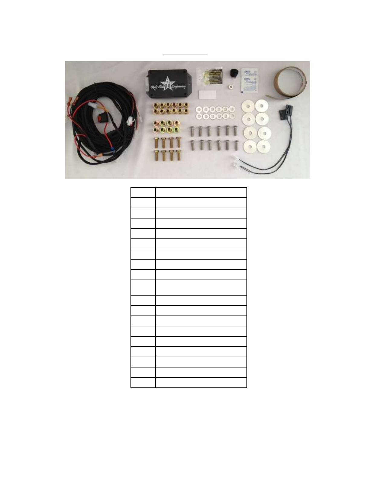
PARTS LIST
QTY
DESCRIPTION
1
Drivers Side Slider Assembly
1
Passenger Side Slider Assembly
1
Wiring Harness
1
Double Sided Sticky Squares
1
Cut Off Switch
1
Anti-Seize Packet
1
Control Box
2
Alcohol Wipes
2
Door Sensors & Actuating
Magnets
2
Grip Tape
4
7/16” Nuts
4
7/16” Washers
8
5/16'' Hex Head Bolts
8
Steel Nutserts
8
Large Washers
10
Aluminum Nutserts
10
5/16” SS Button Head Bolts
10
5/16” Stainless Steel Washers
*If any parts listed are missing or damaged please call Rock-Slide Engineering @
*Optional: 2 LED Light Strips
435-752-4580 prior to installation
Installation Instruction RSEI 123
Page 3
SLIDER INSTALL
1. Remove stock sliders from the Jeep, if equipped.
2. Use a floor jack or buddy to help hold the slider in place in order to mark holes to be
drilled. Take extra care when positioning the slider on the Jeep rocker face to prevent
any scratching or marring of the painted surface. The slider should be tight on the
underside and to the rocker side of the Jeep. Take your time to ensure that the slider is
installed straight and level. Check to make sure that the slider is in the correct position
on the front and rear side, between flares.
3. Mark the side mounting holes on the rocker panel, and on the underside of the tub,
double check for correct fitment. The slider should be tight against the underside and
the rocker side of the body.
4. Remove slider and drill 1/2” holes for nut inserts on the UNDERSIDE. This will
accommodate the larger nut inserts. We suggest using a center punch and a small pilot
drill to precisely drill the center of the hole, for the nut inserts on the side of the body
the hole size needs to be a17/32”. The body sides are very thin metal so let the drill bit
do the work. Don’t push too hard on the drill, possible sheet metal damage may
occur. (don’t over tighten inserts when crimping)
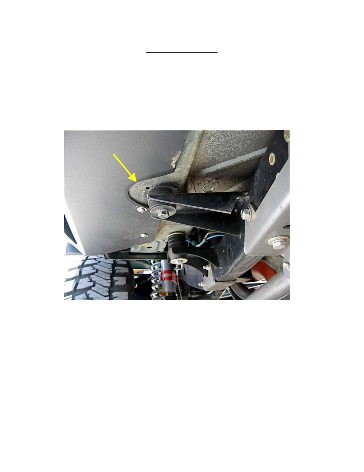
(You will need to add the 3/8” aluminum spacers underneath the back two bolt holes to fill the
gap between the slider and the body of the Jeep)
Installation Instruction RSEI 123
Page 4

5. Install nut inserts with an installation tool if available. If not, install by using a
5/16”x1.125” minimum length bolt with 3/8”nut. Put a small amount of grease on the
bolt to reduce friction. Hold the nut steady with an end wrench so the flange of the
insert is flush against the body panel. Tighten the bolt against the nut to crimp the nut
insert in place. If the insert is rotating, place a star lock washer between the 3/8” nut
and insert. Once it is crimped completely, back out the bolt. If the insert ever breaks
loose and spins, repeat the process and crimp it tighter to prevent spinning.
6. Position the slider into place on the body and match up the holes that you just put in the
side of the body. Make sure that the actuator wire and LED light wire (if applicable) are
free from getting pinched in between the body or frame. Apply a small amount of anti
seize to the button head bolts and start them all before tightening any of them
completely. We recommend tightening the button heads by hand to prevent any
damage to the head of the bolt. Start from the center of the slider and work out
towards the ends, tightening the slider to the rocker face. Install the stainless steel
hardware to hold the slider in place. Slide the spacers into place on the underside of
the slide and install the hardware provided.
7. Once the slider has been secured to the rocker face tighten the body mount bolts on the
underneath side. DO NOT OVERTIGHTEN!!
Installation Instruction RSEI 123
Page 5

WIRING HARNESS INSTALLATION
**Note: The same harness is used for the JK 4-door version **
The additional door sensors are NOT used for the 2-door version
Step Slider Wiring Diagram
Driver Side Wire Color Passenger Side Wire Color
Front Door Sensor Orange/Yellow Front Door Sensor Green/Gray
Driver LED Light Brown/Tan Passenger LED Light Pink/Tan
Driver Actuator Red/Black Passenger Actuator Red/Black
**WARNING**
REMOVE FUSE FROM WIRING HARNESS PRIOR TO INSTALLATION! CONNECTING
THE HARNESS TO THE POWER SOURCE WITH THE FUSE ATTACHED WILL SHORT
OUT THE WIRING HARNESS
NEVER ALLOW THE DOOR SENSOR TO COME INTO DIRECT CONTACT WITH THE
ACTUATING MAGNET. THIS WILL DESTROY THE SENSOR MAKING IT UNUSABLE
1. Roll the rear carpet back underneath the rear seat.
2. The supplied harness is the same for all Jeep applications (Note: You will have some plug connectors
that will not be used). It is important that you secure harness so it is neatly out of the way to avoid
and damage to the wires.
3. Lay the harness into position
4. Start with the electronic box, plug it into the harness and mount it under the seat on the passenger
side.
Installation Instruction RSEI 123
Page 6

5. Divide the harness between the driver and passenger side. Mount the sensors on the driver and
passenger side just underneath the door latch on the inside door frames using the sticky pads
provided. Route the wires around the body seam by placing a small piece of electrical tape on the
body seam. Wrap the wire over the top of the tape towards the inside of the cab then secure the
wire with another piece of electrical tape. (shown above)
6. Drill a hole through the floorboard for the actuator and LED wires from the slider assembly. Route
the wires inside the cab through the hole. Use the floor drain hole if possible.
7. Plug the connectors into the harness. Make sure there is NO interference with the seat belt
system. Secure all wires!
8. Route the system disable switch, POS+ and NEG- wires up the driver side to the “A’ pillar on the
front diver side dash panel.
9. Remove the side dash panel. Drill a hole in the dash to accommodate the switch. Run the three
wires for the disable switch through the dash and plug into the back of the switch. Mount the
ground wire from the plug to a metal surface for the switch illumination.
Installation Instruction RSEI 123
Page 7

10. Route the POS+ and NEG- wires through the firewall on the driver side. Make sure not to interfere
with any of the pedal linkage under the dash.
11. Route wires along the firewall securing the 2 wires to the harness across the firewall.
12. Remove fuse and hook the NEG- to the NEG-side of the battery. POS+ to the POS+ side of the
battery.
13. Position door sensor magnet on the catch side of each door. Make sure the magnet is in line with
the sensor both on top and fore and aft. Make sure no to allow the magnet and sensor to come
into direct contact, this will cause permanent damage to the sensor rendering it unusable.
14. Plug in all connectors; check all wires to make sure that it is completely secure and free from coming
in contact with any moving parts and to prevent system damage due to a cut wire.
15. Close all doors.
16. Insert the fuse into the holder on the POS+ side of the battery.
17. Check each door to ensure the proper alignment of the magnet in relation to the sensor. Once that
proper placement is achieved we recommend using a permanent marker to outline the magnet on
the door.
18. Reinstall all internal plastic and carpet that were removed. Make sure that all wires are tucked back
and out of heavy traffic areas on the floor. Routing them toward the furthest back area underneath
the rear seat.
Installation Instruction RSEI 123
Page 8

MAINTENANCE OF THE STEP SLIDER
Please note the slider is a mechanical mechanism that requires maintenance to operate
properly. To keep the slider operating at an optimal level it needs to be maintained
with lubrication. We recommend using a Teflon based lubrication on the 7 indicated
points below to keep the slider operating smoothly. A good rule of thumb is every time
you change your engine oil. Heavy trail use will increase the frequency in lubrication.
TROUBLE SHOOTING/FRICTION POINTS
The slider is powered by the Jeep’s battery when engine is off and powered by the Jeep’s
engine while the vehicle is running. This will cause the slider to operate at different
speeds depending on the Jeep engine is running or not.
If you feel the slider is sticking at certain points or the motor is stressing it may be
possible a friction point has developed during the install due to a variance in the slider
or Jeep construction.
o To identify a friction point that may be stressing the slider motor, look at the
slider from outside the jeep and open and shut the Jeep door a couple of times
and study the way the slider operates. Look at the slider for wear in the powder
coating. The slider leaves our manufacturing facility with a perfect powder
coating so if you see a spot on the slider that has scratches or the powder coating
shows a blemish; that’s a good indication of a friction point. Using a file or other
grinding tool to smooth over a small area on the slider can alleviate this
problem.
Thank you for choosing Rock-Slide Engineering products. We value your business and
welcome your feedback/suggestions. If you have any concerns please contact us directly @
435-752-4580. We are here to help you!
Installation Instruction RSEI 123
 Loading...