

Page 1
TJ REAR BUMPER
RB-F-100-TJ, RB-F-101-TJ
INSTALLATION INSTRUCTION RSEI 105
Page 2
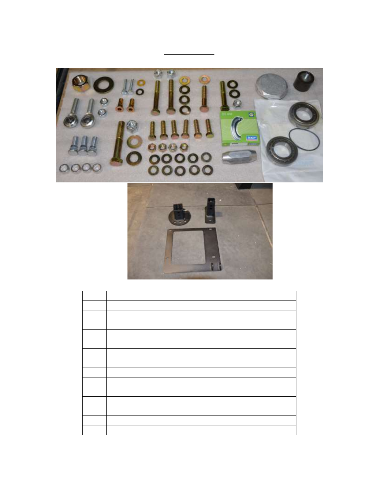
PARTS LIST
QTY
DESCRIPTION
QTY
DESCRIPTION
1
Rear Bumper
1
1'' Washer
1
Tire Carrier
1
Aluminum Cap
1
Tire Mount Bracket
1
O-Ring (140)
1
Tailgate Plate
1
1.25'' Rubber Bumper
2
Nutserts
2
5/16” Washers
1
Seal (5121)
2
5/16'' x 1.5” bolts
1
Left Hand Heim Joint
2
Bearing (Set 5)
1
Right Hand Heim Joint
2
1/2'' x 3.5'' Bolt
1
Left Hand Jam Nut
1
1/2'' x2.5” Bolt
1
Right Hand Jam Nut
3
Lug Studs
1
Turn Buckle
6
7/16'' x 1.5'' Bolt
1
1” Nut
4
7/16'' Nut
1
5/8'' x 3.5'' Bolt
10
7/16” Washer
1
5/8'' Nut
7
1/2'' Washer
INSTALLATION INSTRUCTION RSEI 105
Page 3
*If any parts listed are missing or damaged please call Rock-Slide Engineering @
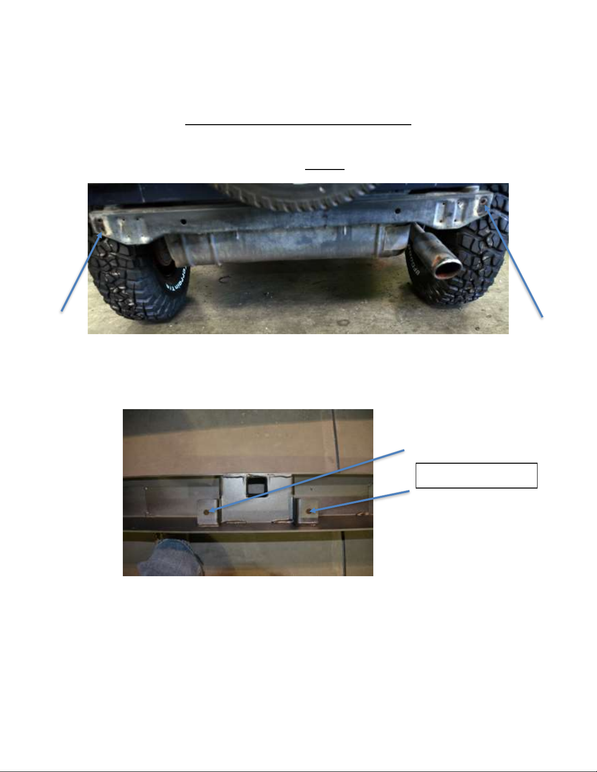
Bumper center holes
435-752-4580 prior to installation
TJ REAR BUMPER INSTALLATION
1. Remove stock bumper and spare tire carrier. Set aside all of the hardware.
a. The tire carrier (8) bolts will be REUSED
2. Position the R-SE bumper into its desired location on the frame cross member. Line
up the bumper holes to the factory mounting holes on each side of the cross
member. (see arrows above for factory mounting holes)
3. Install the nutserts
a. Mark the center holes on the bumper on the frame cross member in order to
drill holes for nutserts
b. Set the bumper down
a. Carefully drill a 7/32’’ pilot hole into the center of the 2 marked points on
frame cross member
b. From the center of the pilot hole, step up the hole size using a ½” bit to
create a finish hole that will be used to install the nutserts
INSTALLATION INSTRUCTION RSEI 105
Page 4

c. Install the 2 nutserts in the holes that were just drilled into the frame
cross member
d. We suggest using a crimping tool to optimize the integrity of the nutserts
to support the slider
e. If no crimping tool is available, follow these instructions
i. Install by using a 5/16’’x1.125’’ minimum length bolt with a 3/8’’
nut
ii. Put a small amount of grease on the bolt to reduce friction
iii. Hold the nut steady with an end wrench so the flange of the insert
is flush against the cross member
iv. Tighten the bolt against the nut to crimp the nutsert into place
v. If the nutsert is rotating, place a star-lock washer between the
3/8’’ nut and nutsert
vi. Once the nutsert is crimped into place completely back out the
bolt
vii. If the nutsert ever breaks loose and spins, repeat the process and
crimp it tighter to prevent spinning
4. Attach Bumper
a. Use the factory holes on the ends and bottom of the frame to attach bumper
b. Loosely attach both sides
c. Attach the center of the bumper to the frame cross member that has nutserts
Completed nutserts should look like this
to the Jeep. Each side of the bumper has two bolts from the frame to the
back of the bumper one bolt from the bottom of the bumper bracket to the
bottom of the frame
INSTALLATION INSTRUCTION RSEI 105
Page 5

d. Tighten all 8 bolts to firmly attach bumper to Jeep
TIRE SWING INSTALLATION
1. Install 2 bearing races into the tire swing mount.
a. The thick side of races MUST face inward
b. Installed correctly the top race has a taper that faces towards the ground,
the bottom race taper points skyward (Diagram below illustrates)
2. With races installed correctly, pack the bottom bearing with grease and install it
into the bottom of the tire carrier with the taper side up.
3. Install the seal by tapping it into the bottom of the tire carrier.
4. Slide the tire carrier, seal and bottom bearing over the bumper spindle.
5. Pack the upper bearing with grease and install it taper side down by sliding it over
the treads on the bumper spindle.
6. Install 1 1’’ washer and 1 1’’ nut to secure tire carrier assembly.
a. Tighten the nut so there is no play in the assembly but loose enough that the
tire carrier still operates in a smooth fashion
7. Place the O-ring inside the aluminum cap and install it over tire carrier assembly.
8. Attach the tailgate plate onto the tailgate using the stock bolts (pictured below, new
version has whole in middle to allow for models with vented tailgates)
a. Some minor trimming to accommodate the vent may be necessary
b. You can reinstall the remaining stock bolts into their original positions
c. Leave the factory rubber bump stops attached to the tailgate
INSTALLATION INSTRUCTION RSEI 105
Page 6

9. Attach Heim Joint on the tailgate side.
a. Using the picture below as a guide. Use a ½” bolt that 3” long for this.
b. Tighten nut so it’s snug but not tight. The joint needs to have play
c. You can put the aluminum spacers in any given configuration as to give you
the spacing that you need for things to clear.
10. Attach the Heim Joint on the swinger side.
a. Using the picture below as a guide, Use a ½” bolt that 3 ½” long for this.
b. Tighten nut so it’s snug but not tight. The joint needs to have play
11. Combine the tailgate and swinger sides using the turnbuckle
a. Use the spacers to make the turnbuckle as level as possible (see below)
INSTALLATION INSTRUCTION RSEI 105
Page 7

12. Attach the rubber stopper to the back of the tire carrier swing at the hole below the
top bolt (as seen below)
13. Pound the 3 lug studs into the tire mount.
a. Determine the best location for your tire size and lug nut pattern
i. *Tire carrier is designed to accommodate up to a 39’’ tire
14. Attach the tire mount to the swing arm using 1/2” x 3 1/2” bolts, 1/2” washer, 1/2”
nuts
15. Tighten the ½” set screw on the tire carrier against the inner sleeve. This will
eliminate any movement or rattling that may occur during driving.
MAKE SURE TO PUT THE BOLTS IN WITH THE HEAD OF THE BOLT TOWARDS THE
JEEP. IF YOU INSTALL THESE INCORRECTLY THE BOLT WILL PUNCH A HOLE IN YOUR
TAILGATE WHEN YOU CLOSE IT OR GO OFF-ROAD.
16. Attach spare tire to the tire mount.
17. Rotate the turnbuckle to take up any movement of the tire carrier.
a. Adjust the turnbuckle to ensure the spare tire carrier does not have any
rattle
b. Make sure the arm rests snuggly against the rubber stopper when the
tailgate is closed
c. When closing the tailgate, the rubber stopper on the swing arm should start
to hit the tailgate when the tailgate is 2.25” from the body (see picture)
INSTALLATION INSTRUCTION RSEI 105
Page 8

d. You should feel some pressure on the door just before it closes
e. ***Do not over tighten as this could cause the tire carrier swing arm to
bend the tailgate***
f. When the tailgate is closed, the spare tire should have no loose movement. If
it moves when you try to rattle it, tighten the turnbuckle more
g. **Take extra care that the tailgate opens and closes freely**
18. Perform a final check of all components to ensure proper fitment and torque.
Thank you for choosing Rock-Slide Engineering products. We value your business
and welcome your feedback/suggestions. If you have any concerns please contact us
directly @ 435-752-4580. We are here to help you!
INSTALLATION INSTRUCTION RSEI 105
 Loading...