

Page 1
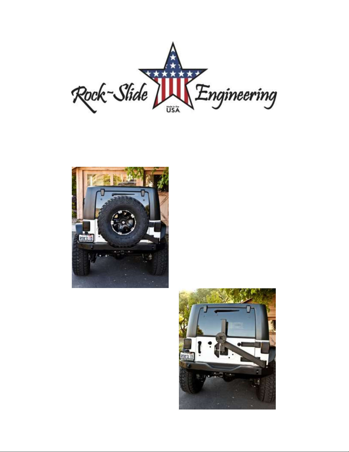
RIGID SERIES REAR BUMPER
RB-F-100-JK, RB-F-101-JK, RB-F-102-JK, RB-F-103-JK
RB-F-100-JKA, RB-F-101-JKA, RB-F-102-JKA, RB-F-103-JKA
INSTALLATION INSTRUCTION RSEI 101
Page 2
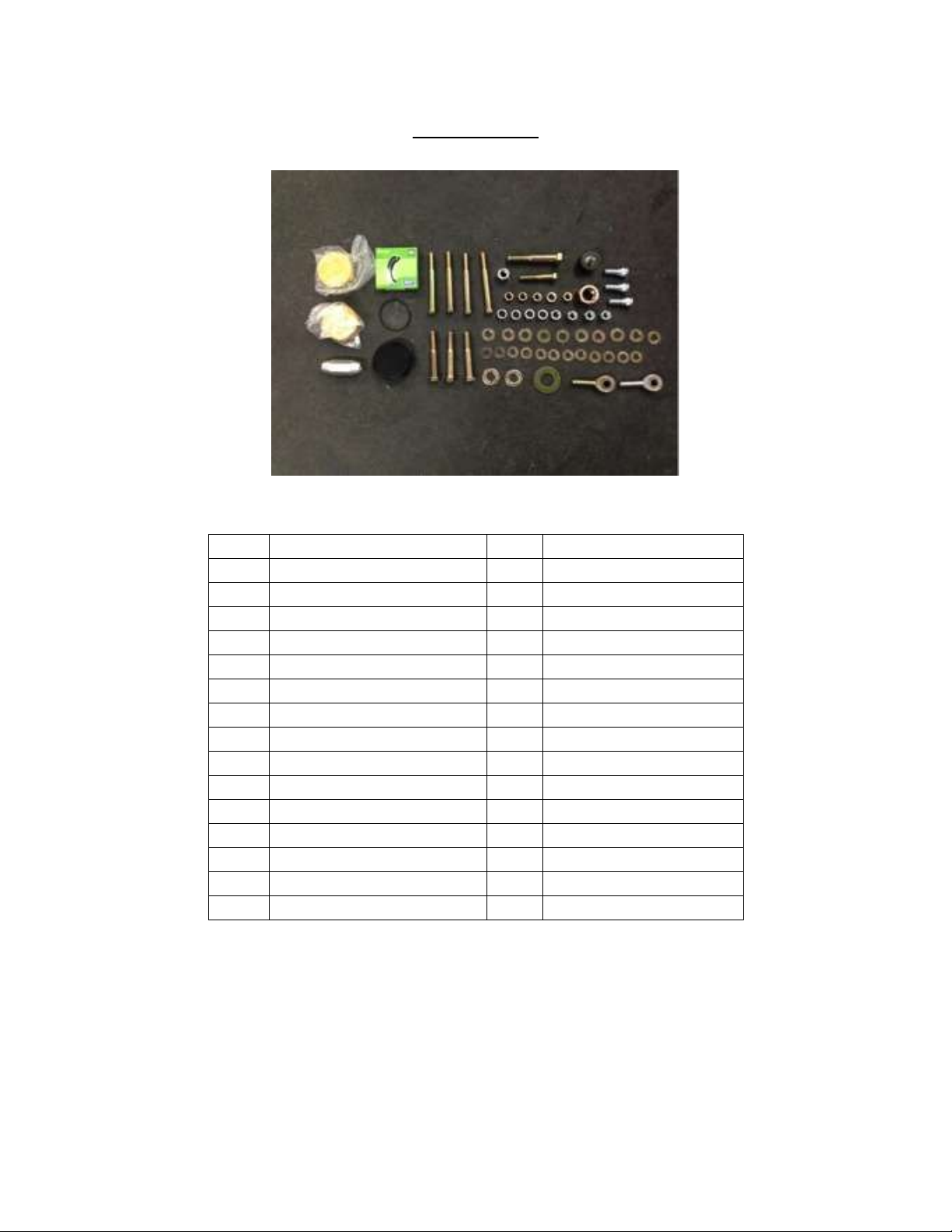
PARTS LIST
QTY
DESCRIPTION
QTY
DESCRIPTION
1
Rear Bumper
1
1'' Washer
1
Tire Carrier
1
Aluminum Cap
1
Tire Mount Bracket
1
O-Ring (140)
1
Tailgate Plate
1
1.25'' Rubber Bumper
1
Mount Adjust Bracket
1
8mm x 1'' Socket Bolt
1
Seal (5121)
2
5/8'' Washer
1
Left Hand Heim Joint
2
Bearing (Set 5)
1
Right Hand Heim Joint
3
1/2'' x 3'' Bolt
1
Left Hand Jam Nut
3
1/2'' Nut
1
Right Hand Jam Nut
3
Lug Studs
1
Turn Buckle
4
7/16'' x 4'' Bolt
1
1/2'' x 2.5'' Bolt
4
7/16'' Nut
1
5/8'' x 3.5'' Bolt
4
1/2'' x 3/8'' Spacer
1
5/8'' Nut
10
1/2'' Washer
1
1'' Nut
12
7/16'' Washer
*If any parts listed are missing or damaged please call Rock-Slide Engineering @
435-752-4580 prior to installation
INSTALLATION INSTRUCTION RSEI 101
Page 3
RIGID SERIES REAR BUMPER INSTALLATION
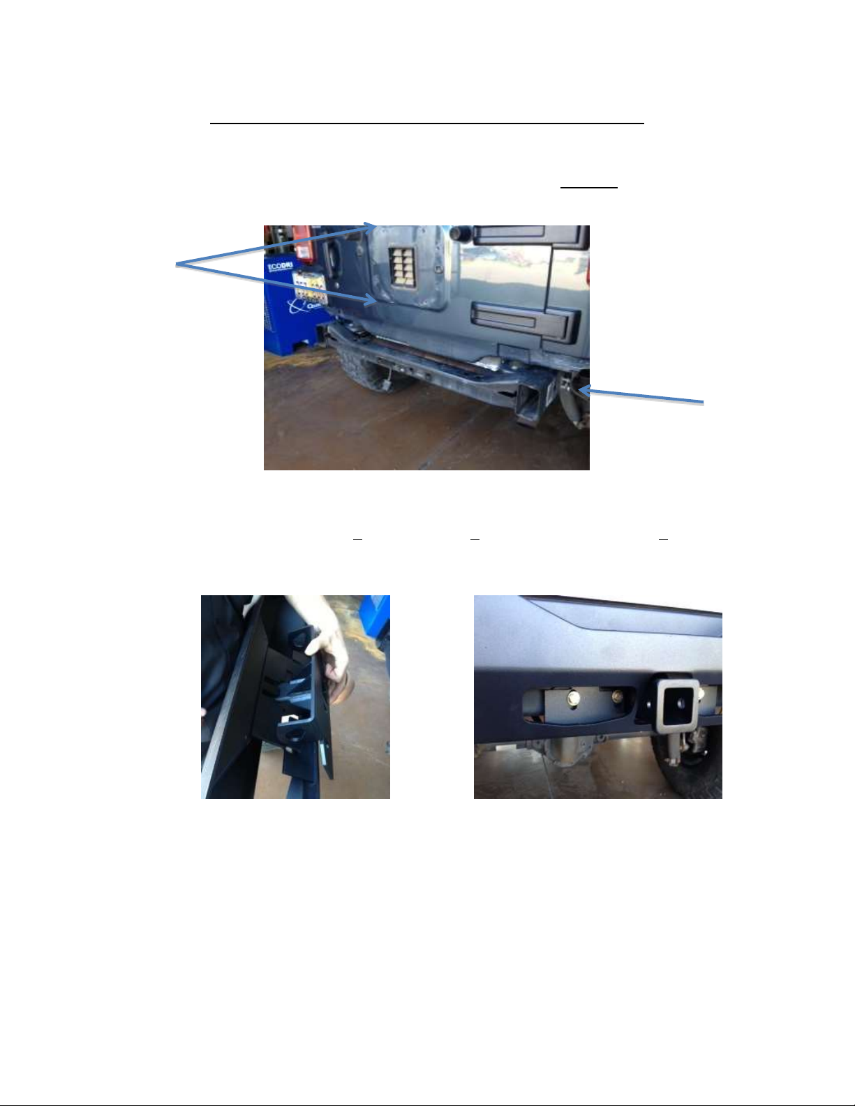
1. Remove stock bumper and set aside all of the hardware.
a. The frame side (4) and tire carrier (8) bolts will be REUSED
b. The stock receiver hitch must be removed as well
Arrows indicate frame side bolts (2 per side) and tire carrier (4 per side)
2. (ALUMINUM ONLY) Place the hitch bracket inside the R-SE bumper and bolt it to the
Jeep’s cross member using 4 7/16’’x4’’ bolts, 8 7/16’’ flange washers, and 4 7/16’’
nuts (below).
a. Hand tighten the bolts at this time leaving room to adjust if needed
3. Position the R-SE bumper into its desired location using the machined slots on the
frame sides. R-SE bumpers are engineered to match the vehicle contour lines;
however subtle body difference may occur.
a. Position the bumper so it’s evenly situated on all sides, leaving at least ¼’’ of
clearance between the bumper and vehicle body
b. Hand tighten the original 4 frame side bolts back into their machined slots
4. Tighten the 4 frame side and 4 cross member bolts.
INSTALLATION INSTRUCTION RSEI 101
Page 4
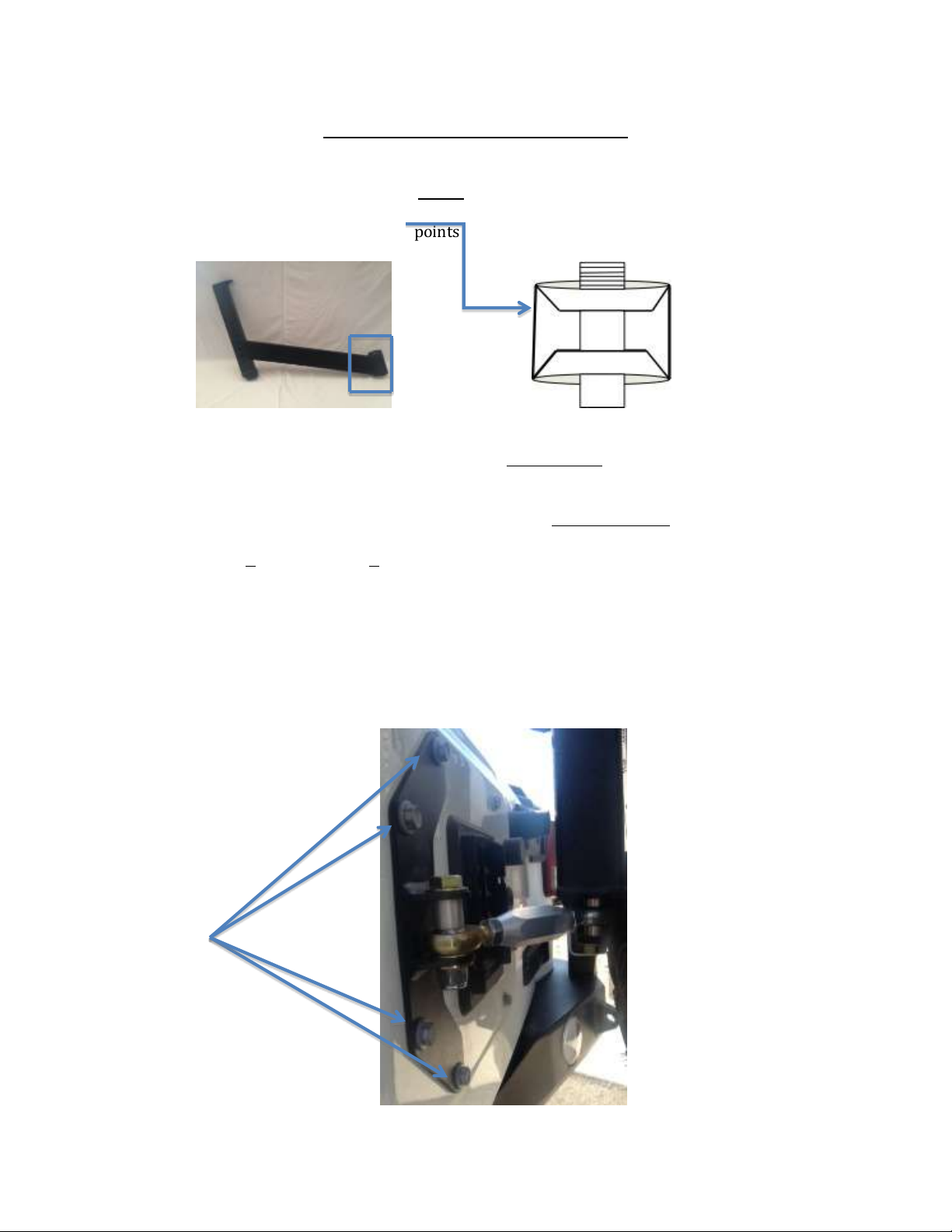
TIRE SWING INSTALLATION
1. Install 2 bearing races into the tire swing mount.
a. The thick side of races MUST face inward
b. Installed correctly the top race has a taper that faces towards the ground,
the bottom race taper points skyward (Diagram below illustrates)
2. With races installed correctly, pack the bottom bearing with grease and install it
into the bottom of the tire carrier with the taper side up.
3. Install the seal by tapping it into the bottom of the tire carrier.
4. Slide the tire carrier, seal and bottom bearing over the bumper spindle.
5. Pack the upper bearing with grease and install it taper side down by sliding it over
the treads on the bumper spindle.
6. Install 1 1’’ washer and 1 1’’ nut to secure tire carrier assembly.
a. Tighten the nut so there is no play in the assembly but loose enough that the
tire carrier still operates in a smooth fashion
7. Place the O-ring inside the aluminum cap and install it over tire carrier assembly.
8. Attach the tailgate plate onto the tailgate using the 4 stock bolts (pictured below).
a. Some minor trimming to accommodate the vent may be necessary
b. You can reinstall the 4 remaining stock bolts into their original positions if
desired but its not required
INSTALLATION INSTRUCTION RSEI 101
Page 5

9. Attach Heim Joint on the tailgate side.
a. Using the picture below as a guide. Use a ½” bolt that 3” long for this.
b. Tighten nut so it’s snug but not tight. The joint needs to have play
c. You can put the aluminum spacers in any given configuration as to give you
the spacing that you need for things to clear.
10. Attach the Heim Joint on the swinger side.
a. Using the picture below as a guide, Use a ½” bolt that 3 ½” long for this.
b. Tighten nut so it’s snug but not tight. The joint needs to have play
11. Combine the tailgate and swinger sides using the turnbuckle.
a. Use the spacers to make the turnbuckle as level as possible
12. Attach the rubber stopper on the tailgate.
INSTALLATION INSTRUCTION RSEI 101
Page 6

13. Pound the 3 lug studs into the tire mount.
a. Determine the best location for your tire size and lug nut pattern
i. *Tire carrier is designed to accommodate up to a 39’’ tire
14. Attach the tire mount to the swing arm using 1/2” x 3 1/2” bolts, 1/2” washer, 1/2”
nuts
15. Tighten the ½” set screw on the tire carrier against the inner sleeve. This will
eliminate any movement or rattling that may occur during driving.
MAKE SURE TO PUT THE BOLTS IN WITH THE HEAD OF THE BOLT TOWARDS THE
JEEP. IF YOU INSTALL THESE INCORRECTLY THE BOLT WILL PUNCH A HOLE IN YOUR
TAILGATE WHEN YOU CLOSE IT OR GO OFF-ROAD.
16. Attach spare tire to the tire mount.
17. Rotate the turnbuckle to take up any movement of the tire carrier.
a. Adjust the turnbuckle to ensure the spare tire carrier does not have any
rattle
b. Make sure the arm rests snuggly against the rubber stopper when the
tailgate is closed
c. When closing the tailgate, the rubber stopper on the swing arm should start
to hit the tailgate when the tailgate is 2.25” from the body (see picture)
d. You should feel some pressure on the door just before it closes
INSTALLATION INSTRUCTION RSEI 101
Page 7

a. ***Do not over tighten as this could cause the tire carrier swing arm to
bend the tailgate***
b. When the tailgate is closed, the spare tire should have no loose movement. If
it moves when you try to rattle it, tighten the turnbuckle more
**Take extra care that the tailgate opens and closes freely**
18. Perform a final check of all components to ensure proper fitment and torque.
Thank you for choosing Rock-Slide Engineering products. We value your business
and welcome your feedback/suggestions. If you have any concerns please contact us
directly @ 435-752-4580. We are here to help you!
INSTALLATION INSTRUCTION RSEI 101
 Loading...