

Page 1

Ram Step Slider Installation
BD-SS-100-RAM, .BD-SS-101-RAM
Installation Instruction RSEI 108
Page 2
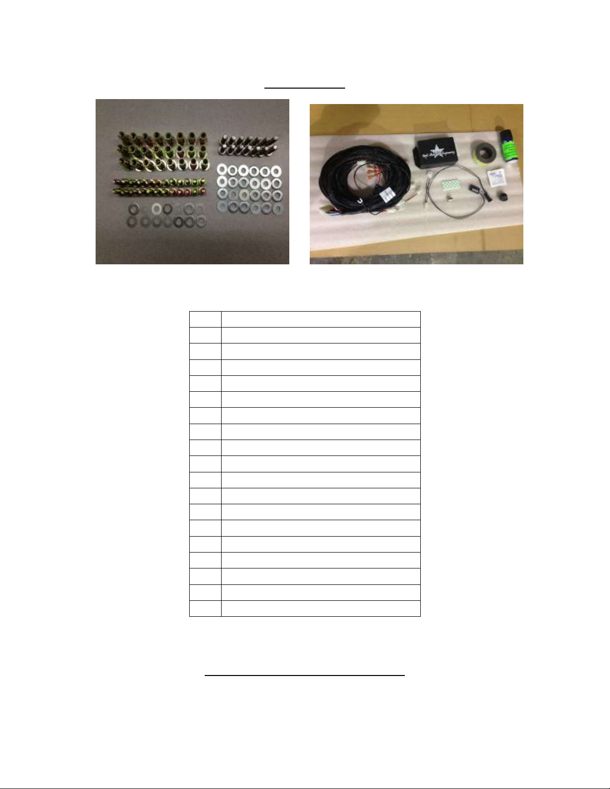
PARTS LIST
DESCRIPTION
1
Drivers Side Slider Assembly
1
Passenger Side Slider Assembly
1
Wiring Harness and Fuse
1
Double Sided Sticky Squares and Alcohol Pad
1
Cut Off Switch
1
Anti-Seize Packet
1
Spray Lubricant
1
Control Box
2
Top Brackets
2
Back brackets
2
Grip Tape Strips
2-4
Brackets (2 Crew Cab, 4 Mega Cab)
4
Actuating Magnets and Door Sensors
24
7/16” Washers
24
1/2" Washers
24
Aluminum Nutserts
14
5/16” SS Button Head Bolts
14
5/16” Stainless Steel Washers
*If any parts listed are missing or damaged please call Rock-Slide Engineering @ 435-752-4580 prior
Installation Instruction RSEI 108
*Optional: 2 LED Light Strips
to installation
STEP SLIDER INSTALLATION
Page 3
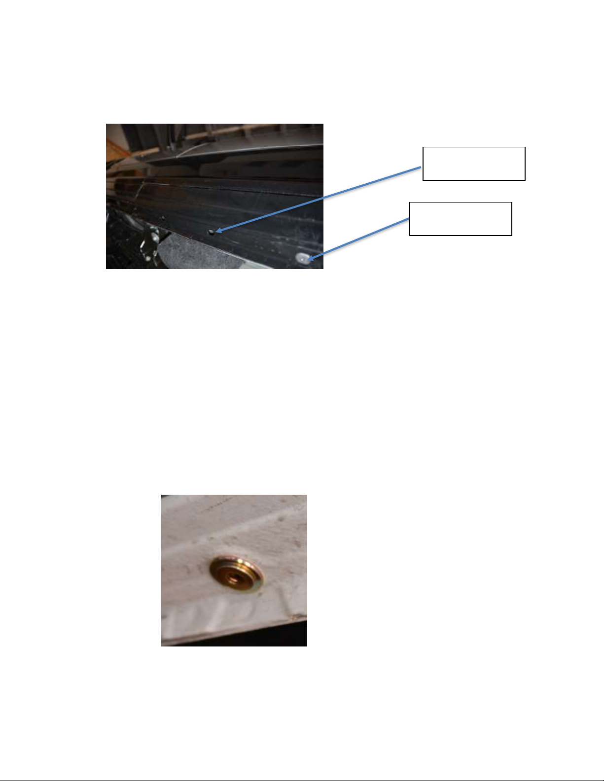
1. Remove the black rubber pieces covering the factory mounting holes on the bottom and
Hole with plastic
removed
Remove plastic
cover
back of the cab pinch seam. The back of cab pinch seam has 6 factory holes in pairs of
two
2. Insert a nutsert with a ½” washer into each of the holes and crimp into place
a. We suggest using a crimping tool to optimize the integrity of the nutserts to
support the slider
b. If no crimping tool is available, follow these instructions
i. Install by using a 5/16’’x1.125’’ minimum length bolt with a 3/8’’ nut
ii. Put a small amount of grease on the bolt to reduce friction
iii. Hold the nut steady with an end wrench so the flange of the insert is flush
against the body panel
iv. Tighten the bolt against the nut to crimp the nutsert into place
v. If the nutsert is rotating, place a star-lock washer between the 3/8’’ nut
and nutsert
vi. Once the nutsert is crimped into place completely back out the bolt
vii. If the nutsert ever breaks loose and spins, repeat the process and crimp it
tighter to prevent spinning
Nutsert properly installed
Installation Instruction RSEI 108
3. The top bracket will be installed first
4. Line up the top bracket front hole to the first factory pinch seam hole towards the front
of the cab
Page 4
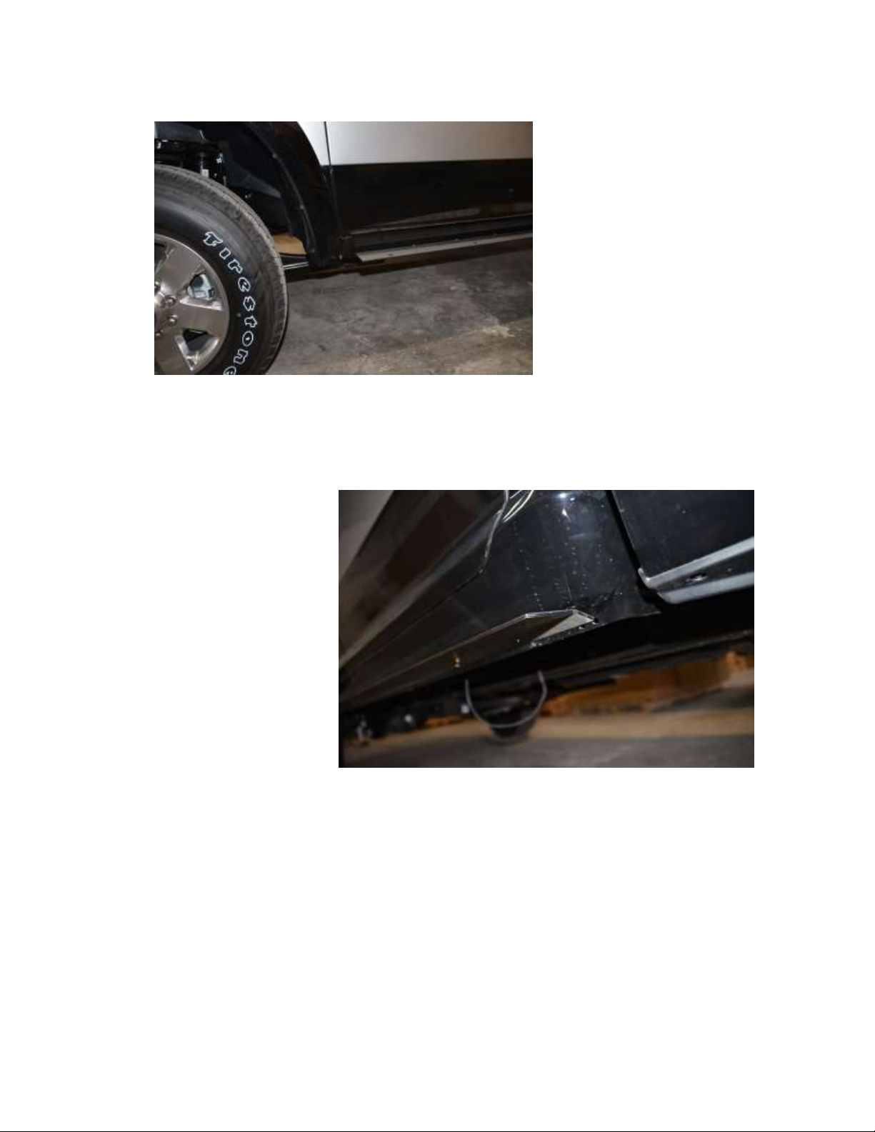
5. Hold the bracket up against the truck panel matching the body angles. Position the
bracket so that the back of the bracket is up against the panel seam. This should leave
the top of the bracket in approximately a level position when installed on the truck,
providing a level bracket for the slider to sit on
6. Bolt the bracket to the truck using the 7/16” bolts and a 7/16” washers. Bolt through
the bracket into the nutsert for each hole on the top bracket
7. Attach the top bracket to the truck
a. Hang bracket on truck and bolt through bracket into the nutserts. Leave bolts
loose until all bolts are installed. Go back and tighten bolts until the bracket is
firm against side of truck
Top bracket installed correctly
Installation Instruction RSEI 108
Page 5

8. Install the back bracket
9. Line up the bracket holes to the matching factory holes
10. Bolt the bracket to the truck using the 7/16” bolts and a 7/16” washers. Bolt through
the bracket into the nutsert for each hole on the top bracket
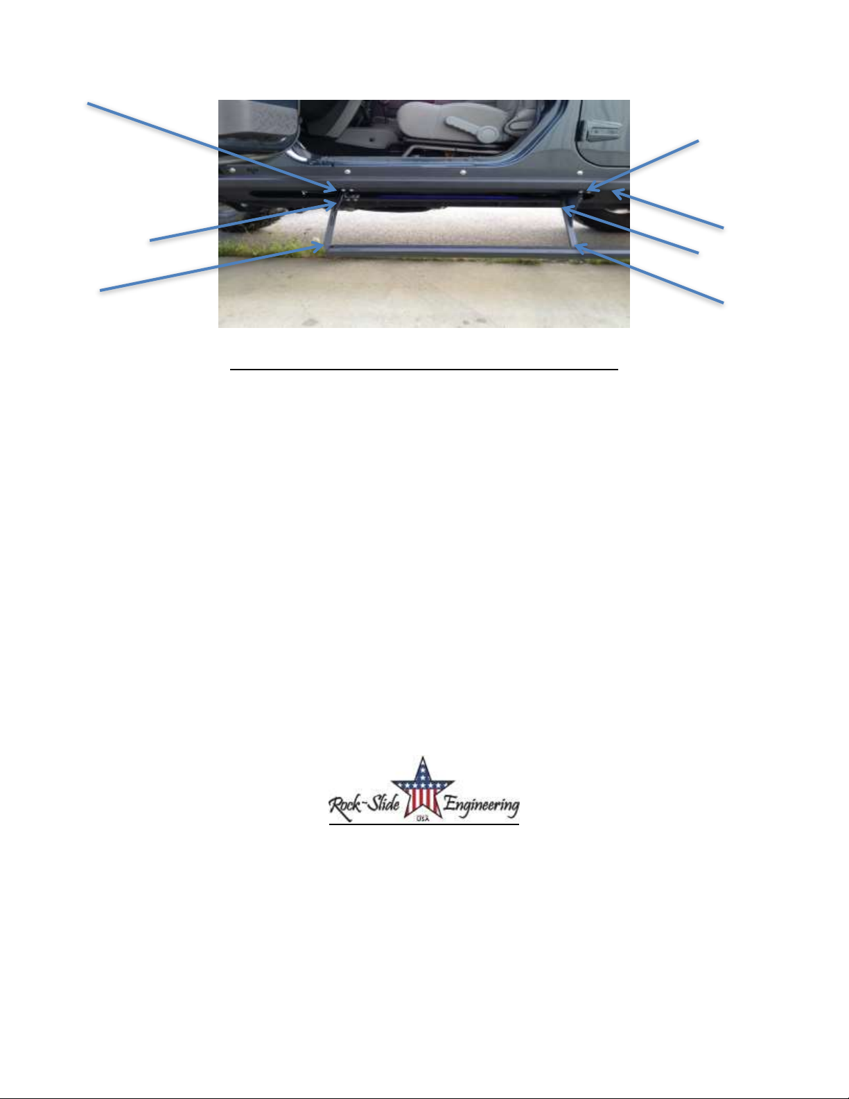
11. Set step slider body onto installed top bracket
12. Place step slider in place and ensure holes from top bracket and back line up with holes
on the step slider body. Brackets can be adjusted slightly by loosening bolts.
13. Make sure wires are run from the step slider body through the hole in the back bracket
14. Bolt the step slider body to the brackets
15. Insert the stainless steel allen head bolts and tighten. BE SURE TO TIGHTEN THESE
BOLTS COMPLETLEY. DO NOT OPEN THE DOOR WITH THESE PARTIALLY INSTALLED,
IT COULD DAMAGE YOUR DOOR.
a. Make sure you put included anti-seize on bolts, since it is stainless steel and
when stainless steel is bolted into steel it can be hard to remove
Installation Instruction RSEI 108
Page 6

16. Make sure all bolts on the brackets and step slider are tight
17. Attach stiffening bracket from the step slider to the body mount bolt located closest to
the center of the step slider
18. Loosen the body mount bolt to give room for the bracket without removing it all the
way
19. Slide the stiffening bracket under the body mount bolt and large factory washer. Don’t
tightening until you bolt the bracket to the step slider
Installation Instruction RSEI 108
Page 7
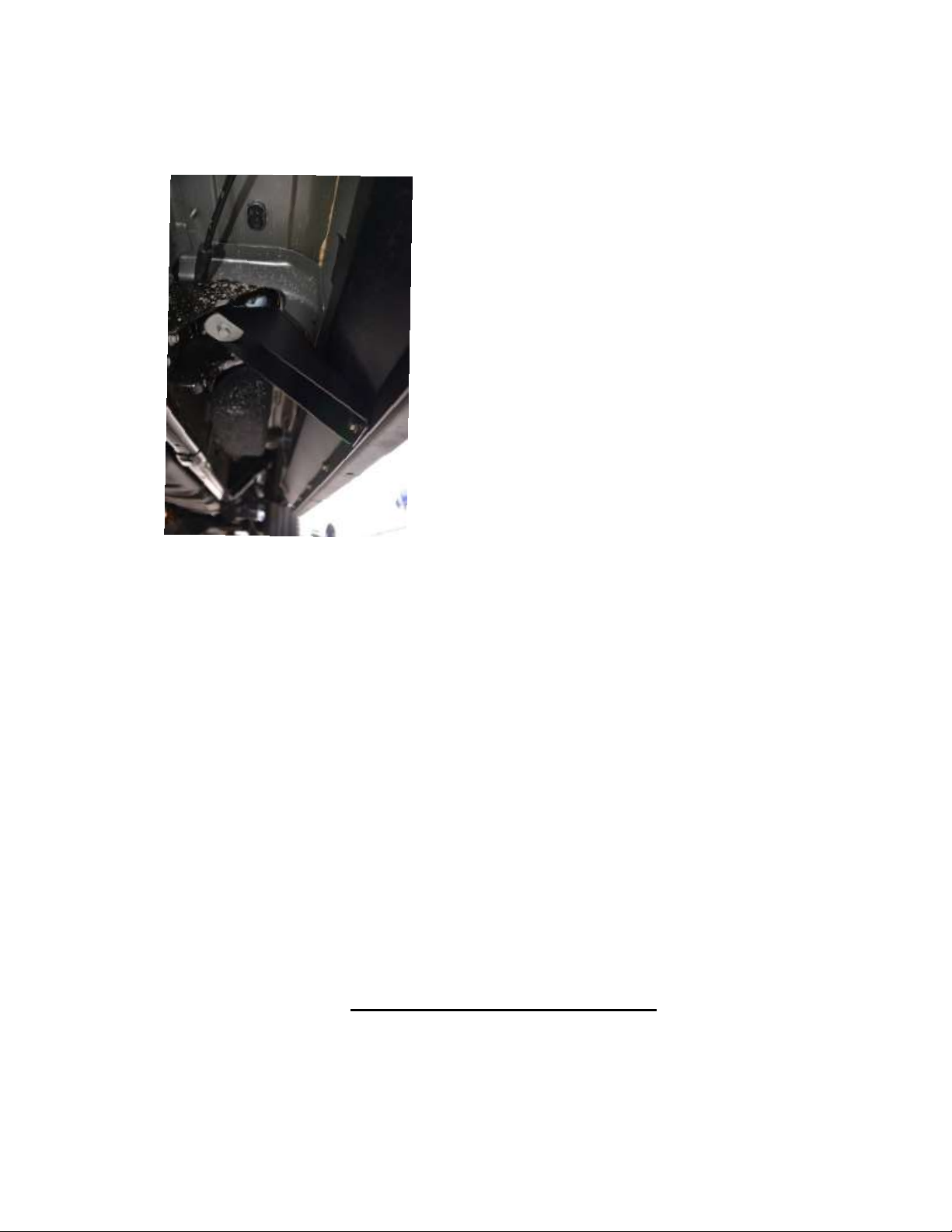
20. Bolt the bottom of the bracket into the step slider body with a 7/16” bolt and washer.
Tighten the bolt into the step slider, then tighten the body bolt to make the bracket tight
21. When the slider is mounted make sure that you have not twisted or manipulated the
shape of the slider with you tightening sequence. THIS WILL CAUSE THE STEP TO NOT
WORK PROPERLY.
22. Double check all bolts to verify components and hardware are installed correctly and
securely to the truck
***Please note: Expect some variance in parts that may require you to adjust the
tension of bolts to make parts fit correctly and properly. Once all parts are installed,
we suggest then fully tightening all bolts again to fit securely***
If you have any questions please contact Rock-Slide Engineering @ 435-752-4580
WIRING HARNESS INSTALL
Installation Instruction RSEI 108
Page 8
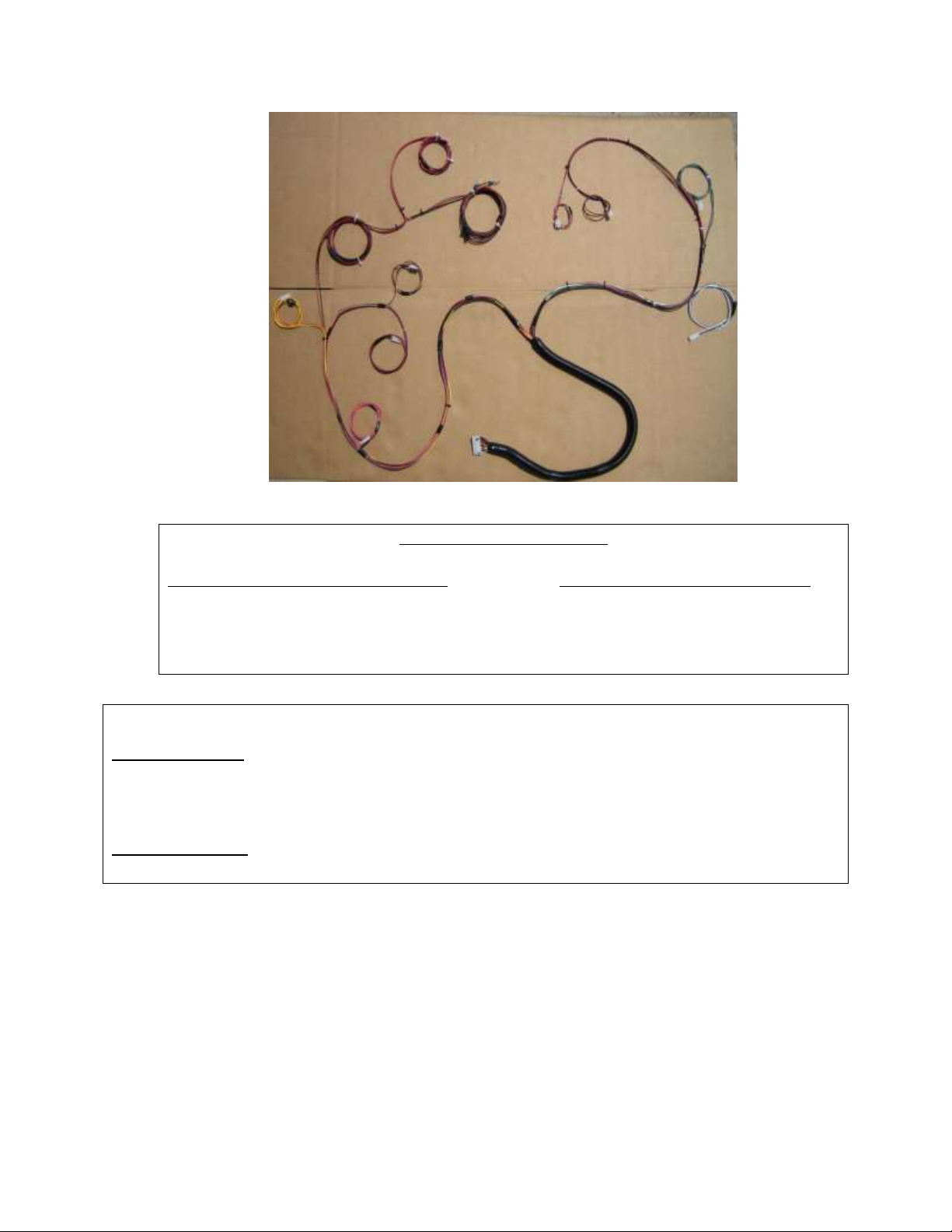
Step Slider Wiring Diagram
Driver Side Wire Color Passenger Side Wire Color
Front Door Sensor Orange/Yellow Front Door Sensor Green/Gray
Rear Door Sensor Orange/Pink Door Sensor Blue/White
Driver LED Light Brown/Tan Passenger LED Light Pink/Tan
Driver Actuator Red/Black Passenger Actuator Red/Black
**WARNING**
REMOVE FUSE FROM WIRING HARNESS PRIOR TO INSTALLATION! CONNECTING
THE HARNESS TO THE POWER SOURCE WITH THE FUSE ATTACHED MAY SHORT
OUT THE WIRING HARNESS.
NEVER ALLOW THE DOOR SENSOR TO COME INTO DIRECT CONTACT WITH THE
ACTUATING MAGNET. THIS WILL DESTROY THE SENSOR MAKING IT UNUSABLE.
1. Remove the sill plate covers on both driver and passenger rear doors
Installation Instruction RSEI 108
Page 9

2. Lay out the wiring harness on the carpet in the back seat
3. Split the harness into the driver’s and passenger side as instructed in wiring diagram
above
4. Position the control box under the rear seat or near the back of the cab, anywhere out of
the way where the wiring harness will fit to both sides of the truck.
a. Choose a location out of sight and in a secure spot so it will not come into contact
with anything or be kicked by a rear seat passenger
5. Plug the harness into the control box and lay the harness wire into position in the truck
starting on the rear passenger side
a. You will want to divide the harness between the rear seats, the front passenger
seat and finish with the driver door. This will reveal how you will be able to
conceal the harness under the carpet when your done
6. Once the harness is positioned in its proposed layout you will need to gain access to the
slider outside the truck to power the slider.
7. Starting on the rear passenger side, run the actuator wires from the slider up through
the floor of the vehicle. THIS MAY REQUIRE YOU TO DRILL AN ACCESS HOLE
DEPENDING ON MODEL AND YEAR. Connect the red/black connector on the wiring
harness.
a. Secure wires to minimize slack so they are protected. We recommend zip ties
b. *Optional: The pink/tan wire is used if LED light package is being installed
8. Inside the truck, route the rear passenger door sensor wire along the doorframe; and
using a sticky pad, mount the sensor underneath the door latch
Installation Instruction RSEI 108
Page 10

Door sensor installed
a. Pull the rubber door seal away from near the latch and run the sensor wires
under the seal.
b. Connect the blue/white wire to the door sensor
c. Place a small piece of electrical tape on the sensor wire to secure the wire from
the truck and protect it on the metal seam
9. While moving to the front passenger door, run the harness under the door sill. Just as
for the back door, route the front passenger door sensor wire up near the latch and
under the door seal.
a. Connect the green/grey wire to door sensor
b. Place a small piece of electrical tape on the sensor wire to secure
10. Returning to the backseat, complete the driver’s side. Run the actuator wires from the
step slider through the floor of the vehicle and plug into the wiring harness. Plug into
the red/black connector into the wiring harness.
a. Secure wires to minimize slack so they are protected. We recommend zip ties
b. *Optional: The brown/tan wire is used if LED light package is being installed
11. Route the rear driver’s side door sensor wire along the doorframe; and using a sticky
pad, mount the sensor underneath the door latch
a. Connect the orange/pink wire to the door sensor
b. Place a small piece of electrical tape on the sensor wire to secure
12. Continue to route the harness wires along the door sill and just like performed on the
passenger side route the door sensor wire up the doorframe and using another sticky
pad, mount the sensor below the door hatch.
a. Connect the orange/yellow wire to the door sensor
b. Place a small piece of electrical tape on the sensor wire to secure
13. Drill an 18 mm hole to mount the cutoff switch. We recommend using a blank switch
spot or near the emergency break release (see picture below).
Installation Instruction RSEI 108
Page 11

Recommended
switch location
THE BRASS COLORED PRONG IS FOR THE GROUND THE SILVER COLORED IS FOR THE POWER
14. Mount the ground from the cutoff switch to a metal surface behind dash panel
15. Route the cutoff switch wires by running the POS+ and NEG- wires rom the wiring
harness plug them into the back of the cutoff switch
16. Route the remaining POS+ and NEG- wires through the firewall on the driver’s side into
the engine compartment. YOU MAY NEED TO DRILL A HOLE THROUGH THE FIREWALL
INTO ENGINE COMPARTMENT
a. Make sure there is NO INTERFERENCE with any of the pedal linkage under the
dash
Installation Instruction RSEI 108
17. Route these wires along the firewall up to the battery compartment
b. Secure the wires using the harness attached to the firewall
18. Attach the NEG- to the NEG- side of the battery
19. Attach the POS+ to the POS+ side of the battery
Page 12

20. Position the actuating magnets on the catch side of each door
c. Make sure the actuating magnets are in perfect line with the sensors
d. **DO NOT allow the magnet and sensor to come into direct contact. This
will destroy the sensor making it unusable**
e. Once that proper placement is achieved we recommend using a permanent
marker to outline the magnet on the door.
21. Re-check all wires to make sure they are completely secure and free from coming into
contact with any moving part to prevent system damage due to a cut wire
22. Reinstall all internal plastic and carpet pieces that were removed.
23. Make sure that all wires are tucked back and out of heavy traffic areas on the floor.
f. Route them toward the furthest back area underneath the rear seat
24. Close all doors
25. Insert the fuse into the holder on the POS+ side of the battery
26. Get in the vehicle. Start it and then turn the cutoff switch into the ON position. The red
Led light should come on. The system is now active. Wait for 10 seconds so the system
can check the system. Open your door and the step will actuate.
MAINTENANCE OF THE STEP SLIDER
Please note the slider is a mechanical mechanism that requires maintenance to operate
properly. To keep the slider operating at an optimal level it needs to be maintained
with lubrication. We recommend using a Teflon based lubrication on the 7 indicated
points below to keep the slider operating smoothly. A good rule of thumb is every time
you change your engine oil. Heavy trail use will increase the frequency in lubrication.
Installation Instruction RSEI 108
Page 13
TROUBLE SHOOTING/FRICTION POINTS
The slider is powered by the truck’s battery when engine is off and powered by the
Truck’s engine while the vehicle is running. This will cause the slider to operate at
different speeds depending on if the truck engine is running or not.
If you feel the slider is sticking at certain points or the motor is stressing it may be
possible a friction point has developed during the install due to a variance in the slider
or truck’s construction
o To identify a friction point that may be stressing the slider motor, look at the
slider from outside the truck and open and shut the truck door a couple of times
and study the way the slider operates. Look at the slider for wear in the powder
coating. The slider leaves our manufacturing facility with a perfect powder
coating so if you see a spot on the slider that has scratches or the powder coating
shows a blemish; that’s a good indication of a friction point. Using a file or other
grinding tool to smooth over a small area on the slider can alleviate this
problem.
Thank you for choosing Rock-Slide Engineering products. We value your business and
welcome your feedback/suggestions. If you have any concerns please contact us directly @
435-752-4580. We are here to help you!
Installation Instruction RSEI 108
 Loading...